
Image not available
Illustrative purposes only

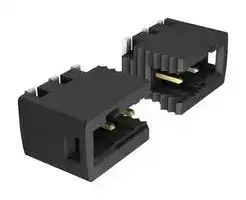
XW4K-08A1-H1
Terminal Block, Header, 2.54 mm, 8 Ways, 6 A, 160 V, Surface Mount Right Angle
⚠️ Reference pricing provided. In case of supply shortages, we will connect you with our trusted procurement partners to ensure your project's continuity.
- Manufacturer: OMRON / PARTNER STOCK
- Product type: Pluggable Terminal Block Headers & Sockets
- SVHC: To Be Advised
- Gender: Header
- Pitch Spacing: 2.54mm
- Product Range: XW4 Series
- Rated Current: 6A
- Rated Voltage: 160V
- No. of Positions: 8Ways
- Block Orientation: Surface Mount Right Angle
| Delivery and price | |
|---|---|
| Units per pack | 1800 |
| Price | 3.45 € |
| Current stock | 500+ |
| Lead time | 30 days |
Datasheet

**XW4H/XW4K/XW4L PCB Terminal Blocks: Push-in SMT Terminals with 2.54mm Pitch**

## **Push-in Terminals to Easily Complete Connections. PCB Terminal Blocks with 2.54mm Pitch.**

- Push-in connection method allows repeated repairs.

- Hold-down structure for strength on PCBs.

- Active lock mechanism for superior vibration and shock resistance.

- Both vertical and horizontal models available.

- Suction cover included to enable automatic mounting. (XW4K/XW4L vertical models)

- Can be mounted to the back surfaces of PCBs.

- Small reel are available. (XW4K/XW4L only)

## **Features**

- Just insert solid wires or ferrules to complete wiring. With Stranded wires, all you need is a flat-blade screwdriver.

**==> picture [342 x 148] intentionally omitted <==**

**----- Start of picture text -----**<br>
Solid wire or ferrule Stranded wires<br>ee<br>Insert the screwdriver into<br>Connection  the release hole and then<br>insert the stranded wires.<br>completed!<br>o "4<br>a —<br>XW4Z-00A<br>**----- End of picture text -----**<br>


- Hold-downs are provided on both ends to achieve robust mounting by increasing solder mounting strength. The hold-downs are circled in red.

- An active lock mechanism prevents the Terminal Blocks from coming off to provide superior vibration and shock resistance.

**==> picture [43 x 7] intentionally omitted <==**

**----- Start of picture text -----**<br>
Active locks<br>**----- End of picture text -----**<br>


**1** ~~a~~

**XW4H/XW4K/XW4L Connection Examples**

**==> picture [379 x 175] intentionally omitted <==**

**----- Start of picture text -----**<br>
XW4H-@@A1<br>ce s (a<br>XW4L-@@A1-V1<br>AEZ (a<br>XW4K-@@A1-H1<br>XW4K-@@A1-V1<br>XW4L-@@A1-H1<br>SE<br>SET S<br>H h gS<br>XW4H-@@A1<br>**----- End of picture text -----**<br>


## **Model Number Legend**

> - - -

> **XW4** ~~HOO~~ **A 1** O ~~O~~ o (1) (2) (3) (4) (5) (6)

**==> picture [34 x 9] intentionally omitted <==**

**----- Start of picture text -----**<br>
(1)Series<br>**----- End of picture text -----**<br>


|**Code**|**Type**|
|---|---|
|H|SMT Terminal Block<br>Connector, Wire Side|
|K|SMT Terminal Block<br>Connector, Board Side<br>SMT Terminal Block|
|L|SMT Terminal Block<br>Direct Board Mounting|


## (2)Terminal Block Number of Contacts

|**Code**|**Number of contacts**|
|---|---|
|02<br>03<br>04<br>05<br>06<br>07|2 contacts<br>3 contacts<br>4 contacts<br>5 contacts<br>6 contacts<br>7 contacts|
|08|8 contacts|
|09|9 contacts|
|10|10 contacts|
|11|11 contacts|
|12|12 contacts|


## (3)Terminal Pitch

|**Code**|**Pitch**|
|---|---|
|A|2.54mm|


## (4)Number of Rows and Specifications

|**Code**<br>1|**Number of rows**<br>1 row|
|---|---|


(5)Connector Shape *

|**Code**|**Appearance**|
|---|---|
|H1|Horizontal|
|V1|Vertical|
|(6)Small reel *||
|**Code**|**Quantity**|
|R100|100pcs|


(6)Small reel *

* XW4K/XW4L only.

## **Terminal Blocks**

**==> picture [511 x 212] intentionally omitted <==**

**----- Start of picture text -----**<br>
a Models  G XW4H- @@ A1 XW4K- @@ A1-V1 XW4K- @@ A1-H1<br>Connector, Wire-side  Connector, Board-side Vertical  Connector, Board-side Horizontal<br>Sockets Plugs Plugs<br>Appearance<br>a Page Page 4 Page 5 Page 5<br>es Models XW4L- @@ A1-V1 XW4L- @@ A1-H1<br>Direct-board-mounting, Vertical  Direct-board-mounting, Horizontal<br>Sockets Sockets<br>Appearance<br>a [ S ] ee<br>a Page Page 6 Page 6<br>Note:  @@ is replaced by the number of contacts.<br>**----- End of picture text -----**<br>


**2**

**XW4H/XW4K/XW4L**

## **Ratings and Specifications**

|**Rated voltage**|160 VAC|
|---|---|
|**Rated current ***|6 A|
|**Dielectric strength**|1,400 V for 1 min|
|**Insulation resistance**|1,000 MΩmin.|
|**Wire stripping length**|6 mm|
|**Operating temperature**|-40 to 125°C (with no condensation or icing)|


- This is the maximum value for the connector.

If the rated current of the cable is lower than the rated current of the connector, use the rated current of the cable.

## **Materials and Finishes**

|**Housing**|LCP/Black|
|---|---|
|**Contacts**|Copper alloy/tin plated|
|**Spring**|SUS|


## **Applicable Wires**

|**Solid wires**|0.14 to 0.5 mm2|
|---|---|
|**Stranded wires**|0.2 to 0.5 mm2|
|**Ferrules**|0.25 to 0.34 mm2|
|**AWG**|26 to 20|


**3**

**XW4H/XW4K/XW4L**

## **XW4H Connectors, Wire Side**

## **Dimensions**

## **XW4H-** @@ **A1**

**==> picture [108 x 121] intentionally omitted <==**

**----- Start of picture text -----**<br>
L+7<br>| 10.5 |<br>14.2<br>is<br>| — A<br>oe<br>4.9<br>2.54 Ps<br>an L<br>**----- End of picture text -----**<br>


**(Unit: mm)**

|**Models**<br>~~ee~~<br>~~es~~|**Number of**<br>**contacts**<br>~~ee~~<br>~~ee~~<br>~~es~~|**L**<br>~~ee~~<br>~~ee~~<br>~~es~~|**A**<br>~~ee~~<br>~~ee~~<br>~~es~~|
|---|---|---|---|
|**XW4H-02A1**<br>~~ee~~<br>~~es~~|2<br>~~ee~~<br>~~ee~~<br>~~es~~|2.54<br>~~ee~~<br>~~ee~~<br>~~es~~|10.38<br>~~ee~~<br>~~ee~~<br>~~es~~|
|**XW4H-03A1**<br>~~es~~<br>~~es~~|3<br>~~es~~<br>~~es~~|5.08<br>~~es~~<br>~~es~~|12.92<br>~~es~~<br>~~es~~|
|**XW4H-04A1**|4<br>~~es~~|7.62|15.46|
|**XW4H-05A1**<br>~~es~~<br>~~es~~|5<br>~~es~~<br>~~es~~<br>~~ee~~|10.16<br>~~es~~|18.00<br>~~es~~|
|**XW4H-06A1**<br>~~es~~<br>~~es~~|6<br>~~es~~<br>~~es~~<br>~~ee~~|12.70<br>~~es~~|20.54<br>~~es~~|
|**XW4H-07A1**<br>~~es ~~<br>~~es~~|7<br>~~es~~<br> ~~ee~~<br>~~es~~|15.24<br>~~es~~|23.08<br>~~es~~|
|**XW4H-08A1**<br>**XW4H-09A1**<br>~~es~~|8<br>9<br>~~es~~|17.78<br>20.32<br>~~es~~|25.62<br>28.16<br>~~es~~|
|**XW4H-09A1**<br>**XW4H-10A1**<br>~~es~~<br>~~es~~|9<br>10<br>~~es~~<br>~~ee~~<br>~~es~~|20.32<br>22.86<br>~~es~~<br>~~es~~|28.16<br>30.70<br>~~es~~<br>~~es~~|
|**XW4H-11A1**<br>~~es~~<br>~~es~~|11<br>~~es~~<br>~~ee~~<br>~~es~~|25.40<br>~~es~~<br>~~es~~|33.24<br>~~es~~<br>~~es~~|
|**XW4H-12A1**<br>~~es~~|12<br>~~es~~|27.94<br>~~es~~|35.78<br>~~es~~|


## **Models**

|**Appearance**<br>**Number of**<br>**contacts**|**Connector, Wire-side**<br>**Sockets**|**Connector, Wire-side**<br>**Sockets**|
|---|---|---|
||**Models**|**Minimum ordering**<br>**quantity (pieces)**|
|**2**|**XW4H-02A1**|100|
|**3**|**XW4H-03A1**||
|**4**|**XW4H-04A1**||
|**5**|**XW4H-05A1**|75|
|**6**|**XW4H-06A1**||
|**7**|**XW4H-07A1**||
|**8**|**XW4H-08A1**|50|
|**9**|**XW4H-09A1**||
|**10**|**XW4H-10A1**||
|**11**|**XW4H-11A1**|25|
|**12**|**XW4H-12A1**||


## **Mating Diagram**

**(Unit: mm)**

**==> picture [194 x 79] intentionally omitted <==**

**----- Start of picture text -----**<br>
XW4H<br>16.95<br>\ FAA _<br>XW4K-V1<br>_ 16.95<br>— fo r<br>rit T L<br>XW4H<br>ch (| XW4K-H1 Db<br>LEE TELE |<br>**----- End of picture text -----**<br>


**4**

**XW4H/XW4K/XW4L**

## **XW4K Connectors, Board Side, Vertical and Horizontal**

## **Dimensions**

**(Unit: mm)**

## **Vertical**

## **XW4K-** @@ **A1-V1**

||||||||||||||||||||||||||Suction cover|Suction cover|Suction cover|Suction cover|Suction cover|Suction cover|Suction cover|**PCB Mating Dimensions**|||||
|---|---|---|---|---|---|---|---|---|---|---|---|---|---|---|---|---|---|---|---|---|---|---|---|---|---|---|---|---|---|---|---|---|---|---|---|---|
|||||||||||||||||||||||||||||||||**(TOP VIEW)**|||||
||||||||||||||||||||||||||||||||||||||
||||||||||||||||2.54|||~~71 ~~||||~~|~~|||L|||||||B+1.27<br>Pin1<br>B+1.27<br>1.1<br>* Positioning<br>boss hole<br>1 dia.|||**Dimensions**<br>**Models**<br>**Number of**<br>**contacts**<br>**L**<br>**A**<br>**B**<br>**C**||
|||||||||||||||||||||||||||||||||0.6<br>3.3||6||**XW4K-02A1-V1**<br>2<br>2.54<br>10.39<br>1.27<br>5.42|
|||||||8.8|||||||||||||||||||A|||||||3.75||||**XW4K-03A1-V1**<br>3<br>5.08<br>12.93<br>2.54<br>6.69|
|5<br>0.6<br>0.8 dia.<br>0.55<br>7.45<br>6.45<br>~~psa~~<br>~~[=~~||||||||||||||0.8 dia.<br>0.9||~~MA ~~<br>~~eK~~||||||||L+2.54<br>5.5<br>L+5.08<br>~~_~~<br>~~=~~<br> ~~Ae~~||||||||C<br>C<br>B+2.54<br>B+2.54<br>B<br>B<br>(Tolerance: ±0.05)<br>Note: The overall pattern pitch tolerance<br>for the board is ±0.05.<br>Do not accumulate error.<br>* The 1-mm diameter holes are for the<br>positioning bosses. Use metal masks to<br>prevent solder from entering these holes.<br>~~—~~<br>~~— ~~||||**XW4K-04A1-V1**<br>4<br>7.62<br>15.47<br>3.81<br>7.96<br>**XW4K-05A1-V1**<br>5<br>10.16<br>18.01<br>5.08<br>9.23<br>**XW4K-06A1-V1**<br>6<br>12.70<br>20.55<br>6.35<br>10.50<br>**XW4K-07A1-V1**<br>7<br>15.24<br>23.09<br>7.62<br>11.77<br>**XW4K-08A1-V1**<br>8<br>17.78<br>25.63<br>8.89<br>13.04<br>**XW4K-09A1-V1**<br>9<br>20.32<br>28.17<br>10.16<br>14.31<br>**XW4K-10A1-V1**<br>10<br>22.86<br>30.71<br>11.43<br>15.58<br>**XW4K-11A1-V1**<br>11<br>25.40<br>33.25<br>12.70<br>16.85<br>**XW4K-12A1-V1**<br>12<br>27.94<br>35.79<br>13.97<br>18.12<br>~~pr~~<br>~~i~~<br> ~~Ca~~<br>~~pr~~<br>~~es~~<br>~~a~~<br>~~es~~<br>~~O~~<br>~~pr~~<br>~~a~~|


## **Horizontal**

## **XW4K-** @@ **A1-H1**

||||||||||||||||||||||||||||||||||||**PCB Mating Dimensions**|||||
|---|---|---|---|---|---|---|---|---|---|---|---|---|---|---|---|---|---|---|---|---|---|---|---|---|---|---|---|---|---|---|---|---|---|---|---|---|---|---|---|
||||7<br>6.45||||||||2.54||||||||||L||||||||||||||**(TOP VIEW)**|||||
|5<br>0.9||~~i~~|||||0.6<br>0.8 dia.|||0.8 dia.||~~|~~|||||~~a~~||||A|||||~~|~~||||||4.1<br>3.5||* Positioning|0.2<br>B+1.27<br>B+1.27<br>1.1<br>0.4<br>Pin1<br>* Positioning<br>boss hole<br>1 dia.||6<br>**Dimensions**<br>**Models**<br>**Number of**<br>**contacts**<br>**L**<br>**A**<br>**B**<br>**C**<br>**XW4K-02A1-H1**<br>2<br>2.54<br>10.39<br>1.27<br>5.42|||
||||||||||||||||||||||||||||||||||||||||**XW4K-03A1-H1**<br>3<br>5.08<br>12.93<br>2.54<br>6.69|
||||||||||||||||||||L+2.54<br>L+5.08||||||||||||||||C<br>C<br>B+2.54<br>B+2.54<br>B<br>2.54<br>B||||**XW4K-04A1-H1**<br>4<br>7.62<br>15.47<br>3.81<br>7.96<br>**XW4K-05A1-H1**<br>5<br>10.16<br>18.01<br>5.08<br>9.23<br>**XW4K-06A1-H1**<br>6<br>12.70<br>20.55<br>6.35<br>10.50<br>~~ee~~<br>~~pr~~|
||||||||||||||||||||||||||||||||||||(Tolerance: ±0.05)<br>Note: The overall pattern pitch tolerance<br>for the board is ±0.05.<br>Do not accumulate error.<br>* The 1-mm diameter holes are for the||||**XW4K-07A1-H1**<br>7<br>15.24<br>23.09<br>7.62<br>11.77<br>**XW4K-08A1-H1**<br>8<br>17.78<br>25.63<br>8.89<br>13.04<br>**XW4K-09A1-H1**<br>9<br>20.32<br>28.17<br>10.16<br>14.31<br>**XW4K-10A1-H1**<br>10<br>22.86<br>30.71<br>11.43<br>15.58<br>~~pr~~<br>~~es~~<br>~~a~~<br>~~es~~<br>~~O~~<br>~~pr~~|
||||||||||||||||||||||||||||||||||||positioning bosses. Use metal masks to<br>prevent solder from entering these holes.||||**XW4K-11A1-H1**<br>11<br>25.40<br>33.25<br>12.70<br>16.85<br>**XW4K-12A1-H1**<br>12<br>27.94<br>35.79<br>13.97<br>18.12<br>~~pr~~<br>~~SC~~|


## **Models**

|**Appearance**<br>**Number of**<br>**contacts**|**Connector, Board-side Vertical Plugs**|**Connector, Board-side Vertical Plugs**|**Connector, Board-side Horizontal Plugs**|**Connector, Board-side Horizontal Plugs**|
|---|---|---|---|---|
||**500 pcs per reel ***|**100 pcs per reel ***|**600 pcs per reel ***|**100 pcs per reel ***|
|**2**<br>~~a~~|**XW4K-02A1-V1**|**XW4K-02A1-V1-R100**|**XW4K-02A1-H1**|**XW4K-02A1-H1-R100**|
|**3**<br>~~a ~~<br>~~ee~~|**XW4K-03A1-V1**<br> ~~a~~|**XW4K-03A1-V1-R100**|**XW4K-03A1-H1**|**XW4K-03A1-H1-R100**|
|**4**<br> <br>~~ee~~<br>~~ee~~|**XW4K-04A1-V1**<br> ~~a~~<br>~~a~~|**XW4K-04A1-V1-R100**|**XW4K-04A1-H1**|**XW4K-04A1-H1-R100**|
|**5**<br> <br>~~ee~~<br>~~ee~~<br>~~ee~~|**XW4K-05A1-V1**<br> ~~a~~<br>~~a~~|**XW4K-05A1-V1-R100**|**XW4K-05A1-H1**|**XW4K-05A1-H1-R100**|
|**6**<br>~~ee ~~<br>~~ee~~|**XW4K-06A1-V1**<br> ~~a~~|**XW4K-06A1-V1-R100**|**XW4K-06A1-H1**|**XW4K-06A1-H1-R100**|
|**7**<br>~~ee~~<br>~~a ~~<br>~~ee~~|**XW4K-07A1-V1**<br> ~~a~~|**XW4K-07A1-V1-R100**|**XW4K-07A1-H1**|**XW4K-07A1-H1-R100**|
|**8**<br>~~ee~~<br>~~ee~~|**XW4K-08A1-V1**<br>~~a~~|**XW4K-08A1-V1-R100**|**XW4K-08A1-H1**|**XW4K-08A1-H1-R100**|
|**9**<br>~~ee~~<br>~~ee~~<br>~~ee~~|**XW4K-09A1-V1**<br>~~a~~<br>|**XW4K-09A1-V1-R100**<br>|**XW4K-09A1-H1**<br>|**XW4K-09A1-H1-R100**<br>|
|**10**<br>~~ee ~~<br>~~ee~~|**XW4K-10A1-V1**<br> ~~a~~<br>|**XW4K-10A1-V1-R100**<br>|**XW4K-10A1-H1**<br>|**XW4K-10A1-H1-R100**<br>|
|**11**<br>~~eea~~|**XW4K-11A1-V1**<br>~~a~~<br>~~a~~|**XW4K-11A1-V1-R100**<br>~~a~~<br>~~a~~|**XW4K-11A1-H1**<br>~~a~~<br>~~a~~|**XW4K-11A1-H1-R100**<br>~~a~~<br>~~a~~|
|**12**<br>~~a~~|**XW4K-12A1-V1**<br>~~a~~|**XW4K-12A1-V1-R100**<br>~~a~~|**XW4K-12A1-H1**<br>~~a~~|**XW4K-12A1-H1-R100**<br>~~a~~|


* Please order an integer multiple of the quantity per reel.

**5**

**XW4H/XW4K/XW4L**

**(Unit: mm)**

## **XW4L Direct Board Mounting, Vertical and Horizontal**

## **Dimensions**

## **Vertical**

## **XW4L-** @@ **A1-V1**

**==> picture [473 x 167] intentionally omitted <==**

**----- Start of picture text -----**<br>
Suction cover PCB Mating Dimensions<br>(TOP VIEW)<br>B+1.27 B+1.27<br>* Positioning  B B<br>2.54 boss hole 2.54<br>L 1 dia. 1.3 (Tolerance: ±0.05)<br>L+5.08 3.1 Note: The overall pattern pitch tolerance<br>A 6 4.15 3.3 for the board is ±0.05. Do not accumulate error.<br>8.84.9 L+2.985.5 6 4.15 3.3 0.6 6 * The 1-mm diameter holes are for the positioning bosses. Use metal masks to prevent solder from entering these holes.<br>C C 1.1<br>B+2.54 B+2.54<br>10.6 9.6<br>D D<br>0.6 0.6 L+2.54<br>0.8 dia.<br>**----- End of picture text -----**<br>


## **Dimensions**

|**Models**|**Number of**<br>**contacts**|**L**|**A**|**B**|**C**|**D**|
|---|---|---|---|---|---|---|
|**XW4L-02A1-V1**|2|2.54|9.77|1.27|2.22|5.16|
|**XW4L-03A1-V1**|3|5.08|12.31|2.54|3.49|6.43|
|**XW4L-04A1-V1**|4|7.62|14.85|3.81|4.76|7.70|
|**XW4L-05A1-V1**|5|10.16|17.39|5.08|6.03|8.97|
|**XW4L-06A1-V1**|6|12.70|19.93|6.35|7.30|10.24|
|**XW4L-07A1-V1**|7|15.24|22.47|7.62|8.57|11.51|
|**XW4L-08A1-V1**|8|17.78|25.01|8.89|9.84|12.78|
|**XW4L-09A1-V1**|9|20.32|27.55|10.16|11.11|14.05|
|**XW4L-10A1-V1**|10|22.86|30.09|11.43|12.38|15.32|
|**XW4L-11A1-V1**|11|25.40|32.63|12.70|13.65|16.59|
|**XW4L-12A1-V1**|12|27.94|35.17|13.97|14.92|17.86|


**Horizontal XW4L-** @@ **A1-H1**

**PCB Mating Dimensions (TOP VIEW)**

**==> picture [465 x 141] intentionally omitted <==**

**----- Start of picture text -----**<br>
9.2 Pin1 (TOP VIEW)<br>5<br>D D<br>0.9<br>B+2.54 B+2.54<br>0.8 dia. 2.54L * Positioning boss hole1 dia. B+1.27 B+1.27 1.1 (Tolerance: ±0.05)Note: The overall pattern pitch tolerance<br>L+2.98L+5.08A 7.054.2 4.4 0.75 Pin1 4.7 1.35 6 * The 1-mm diameter holes are for the positioning bosses. Use metal masks to prevent solder from entering these holes.for the board is ±0.05. Do not accumulate error.<br>2.55 2.54 1.3<br>D D<br>0.6 C C<br>L+2.54<br>**----- End of picture text -----**<br>


## **Dimensions**

|**Models**|**Number of**<br>**contacts**|**L**|**A**|**B**|**C**|**D**|
|---|---|---|---|---|---|---|
|**XW4L-02A1-H1**|2|2.54|9.77|1.27|2.22|5.16|
|**XW4L-03A1-H1**|3|5.08|12.31|2.54|3.49|6.43|
|**XW4L-04A1-H1**|4|7.62|14.85|3.81|4.76|7.70|
|**XW4L-05A1-H1**|5|10.16|17.39|5.08|6.03|8.97|
|**XW4L-06A1-H1**|6|12.70|19.93|6.35|7.30|10.24|
|**XW4L-07A1-H1**|7|15.24|22.47|7.62|8.57|11.51|
|**XW4L-08A1-H1**|8|17.78|25.01|8.89|9.84|12.78|
|**XW4L-09A1-H1**|9|20.32|27.55|10.16|11.11|14.05|
|**XW4L-10A1-H1**|10|22.86|30.09|11.43|12.38|15.32|
|**XW4L-11A1-H1**|11|25.40|32.63|12.70|13.65|16.59|
|**XW4L-12A1-H1**|12|27.94|35.17|13.97|14.92|17.86|


**6**

**XW4H/XW4K/XW4L**

**Models**

|**Appearance**<br>**Number of**<br>**contacts**<br>~~mw~~|**Direct-board-mounting, Vertical Sockets**<br>~~mw~~|**Direct-board-mounting, Vertical Sockets**<br>~~mw~~|**Direct-board-mounting, Horizontal Sockets**<br>~~mw~~|**Direct-board-mounting, Horizontal Sockets**<br>~~mw~~|
|---|---|---|---|---|
||**250 pcs per reel ***<br>~~mw~~|**100 pcs per reel ***<br>~~mw~~|**500 pcs per reel ***<br>~~mw~~|**100 pcs per reel ***<br>~~mw~~|
|2<br>~~mw~~<br>~~a CO~~|**XW4L-02A1-V1**<br>~~mw~~<br>~~CO~~|**XW4L-02A1-V1-R100**<br>~~mw~~<br>~~CO~~|**XW4L-02A1-H1**<br>~~mw~~<br>~~CO~~|**XW4L-02A1-H1-R100**<br>~~mw~~<br>~~CO~~|
|3<br>~~a GG~~|**XW4L-03A1-V1**<br>~~GG~~|**XW4L-03A1-V1-R100**<br>~~GG~~|**XW4L-03A1-H1**<br>~~GG~~|**XW4L-03A1-H1-R100**<br>~~GG~~|
|4<br>~~a~~|**XW4L-04A1-V1**|**XW4L-04A1-V1-R100**|**XW4L-04A1-H1**|**XW4L-04A1-H1-R100**|
|5<br>~~a~~<br>~~a GO~~|**XW4L-05A1-V1**<br>~~GO~~|**XW4L-05A1-V1-R100**<br>~~GO~~|**XW4L-05A1-H1**<br>~~GO~~|**XW4L-05A1-H1-R100**<br>~~GO~~|
|6<br>~~a GO~~<br>~~a GO~~|**XW4L-06A1-V1**<br>~~GO~~<br>~~GO~~|**XW4L-06A1-V1-R100**<br>~~GO~~<br>~~GO~~|**XW4L-06A1-H1**<br>~~GO~~<br>~~GO~~|**XW4L-06A1-H1-R100**<br>~~GO~~<br>~~GO~~|
|7<br>~~a GO~~<br>~~OO~~|**XW4L-07A1-V1**<br>~~GO~~<br>~~OO~~|**XW4L-07A1-V1-R100**<br>~~GO~~<br>~~OO~~|**XW4L-07A1-H1**<br>~~GO~~<br>~~OO~~|**XW4L-07A1-H1-R100**<br>~~GO~~<br>~~OO~~|
|8<br>~~OO~~<br>~~OO~~|**XW4L-08A1-V1**<br>~~OO~~<br>~~OO~~|**XW4L-08A1-V1-R100**<br>~~OO~~<br>~~OO~~|**XW4L-08A1-H1**<br>~~OO~~<br>~~OO~~|**XW4L-08A1-H1-R100**<br>~~OO~~<br>~~OO~~|
|9<br>~~OO~~<br>~~a OO~~|**XW4L-09A1-V1**<br>~~OO~~<br>~~OO~~|**XW4L-09A1-V1-R100**<br>~~OO~~<br>~~OO~~|**XW4L-09A1-H1**<br>~~OO~~<br>~~OO~~|**XW4L-09A1-H1-R100**<br>~~OO~~<br>~~OO~~|
|10<br>~~a OO~~<br>~~a GO~~|**XW4L-10A1-V1**<br>~~OO~~<br>~~GO~~|**XW4L-10A1-V1-R100**<br>~~OO~~<br>~~GO~~|**XW4L-10A1-H1**<br>~~OO~~<br>~~GO~~|**XW4L-10A1-H1-R100**<br>~~OO~~<br>~~GO~~|
|11<br>~~a GO~~<br>~~OO~~<br>~~i a~~|**XW4L-11A1-V1**<br>~~GO~~<br>~~OO~~<br>~~a~~|**XW4L-11A1-V1-R100**<br>~~GO~~<br>~~OO~~<br>~~Ge~~|**XW4L-11A1-H1**<br>~~GO~~<br>~~OO~~|**XW4L-11A1-H1-R100**<br>~~GO~~<br>~~OO~~|
|12<br>~~i a~~|**XW4L-12A1-V1**<br>~~a~~|**XW4L-12A1-V1-R100**<br>~~Ge~~|**XW4L-12A1-H1**|**XW4L-12A1-H1-R100**|


* Please order an integer multiple of the quantity per reel.

## **Accessories**

## **Special Screwdriver**

## **XW4Z-00A**

**==> picture [172 x 27] intentionally omitted <==**

**----- Start of picture text -----**<br>
Models Minimum ordering<br>quantity (pieces)<br>XW4Z-00A 1<br>**----- End of picture text -----**<br>


## **Safety Precautions**

## ~~PF~~ **Precautions for Correct Use**

## ● **Soldering Conditions**

- Recommended Reflow Conditions Maximum temperature: 255°C Time: Within 20 s

**==> picture [191 x 86] intentionally omitted <==**

**----- Start of picture text -----**<br>
(°C)<br>Peak temperature 255<br>Co) Soldering temperature  Op 240 AA<br>Preheating temperature 150<br>(s)<br>Preheating time:  Soldering time:<br>ee Within 60 to 120 s Within 20 to 40 s<br>**----- End of picture text -----**<br>


These conditions depend on the type of solder, the manufacturer, the amount of solder, the size of the circuit board, and the other mounting materials. You must check and select the actual conditions yourself.

## ● **Metal Mask Thickness for Cream Solder**

## **Printing**

We recommend a metal mask thickness of 0.12 to 0.15 mm for cream solder printing.

These conditions, however, depend on the type of solder, the manufacturer, the amount of solder, the size of the circuit board, and the other mounting materials. You must check and select the actual conditions.

## ● **Pin Deformation**

The pins will deform if you subject them to an excessive load. Deformed pins will reduce solderability when the Connectors are mounted. Do not drop the Connectors or handle them roughly. Do not connect or disconnect Connectors that are not mounted to a circuit board. Doing so may deform the pins.

**7**

## **XW4H, XW4L**

## ● **Wiring Terminal Blocks**

## **Directly Connecting Wires**

- (1) Use wires with conductors that are within the connectible wire range.

- (2) Prepare the ends of the wires as shown below. Refer to Ratings and Specifications for the wire stripping length.

   - 6[±1mm]

- (3) Do not presolder the ends of the wires. Doing so will prevent correct connections.

## ● **Connection Methods**

## **Using Ferrules or Solid Wire**

## ● **Terminal Block Connection Method**

## **Using Crimp Terminals**

- (1) Use ferrules or tab terminals.

However, the Terminal Blocks are small, so sufficiently confirm the following before you use them.

- (2) Insulation between Crimp Terminals

If you use naked crimp terminals, there will be no finger protection. Also, there will be limited clearance and creepage distances between adjacent terminals, so use crimp terminals with care.

## ● **Special Screwdriver for Terminal Blocks**

Use the XW4Z-00A Special Screwdriver to connect the Terminal Blocks.

You can also use any screwdriver with the following dimensions. If you use any screwdriver other than the Special Screwdriver or one with the following dimensions, the Terminal Block may be damaged.

**==> picture [509 x 231] intentionally omitted <==**

**----- Start of picture text -----**<br>
Connection Method Removal Method<br>(Unit: mm)<br>Release holes<br>A<br>A<br>0.4<br>2 dia.<br>Terminal insertion holes<br>9<br>Just press the ferrule all  Insert the screwdriver<br>the way in. into the release hole  2<br>and pull out the ferrule.<br>a Using Stranded Wires a<br>40<br>Using Stranded Wires<br>To insert a stranded wire, insert a screwdriver<br>into the release hole and then insert the wire.<br>To remove a stranded wire, insert a screwdriver<br>into the release hole and then pull out the wire.<br>**----- End of picture text -----**<br>


**Note:** Do not apply excessive force to the Terminal Block when you insert the tool. The Terminal Block may be damaged.

> • Application examples provided in this document are for reference only. In actual applications, confirm equipment functions and safety before using the product.

> • Consult your OMRON representative before using the product under conditions which are not described in the manual or applying the product to nuclear control systems, railroad systems, aviation systems, vehicles, combustion systems, medical equipment, amusement machines, safety equipment, and other systems or equipment that may have a serious influence on lives and property if used improperly. Make sure that the ratings and performance characteristics of the product provide a margin of safety for the system or equipment, and be sure to provide the system or equipment with double safety mechanisms.

**Note: Do not use this document to operate the Unit.**

**OMRON Corporation Electronic and Mechanical Components Company**

**Contact:  www.omron.com/ecb**

**Cat. No. G090-E1-03**

0816(0515)
Updated at April 28, 2026
About Novapart
Novapart is a B2B electronic component broker specialising in stock shortages and cost reduction. We source hard-to-find parts and identify compliant alternatives across a catalogue of 410,000+ components from 500+ manufacturers.
Learn more →Stock Shortage Specialist
When a component is unavailable, discontinued or has an unacceptable lead time, we tap into our network of vetted European and Asian distributors to source what you need — without compromising on quality or traceability.
Request a quote →Compliant Alternatives
We identify pin-to-pin, electrically equivalent substitutes that meet the same certifications (RoHS, AEC-Q100, REACH) as your original specification — validated against datasheets, not just part numbers. Often at a lower cost.
BOM Analysis service →