
Image not available
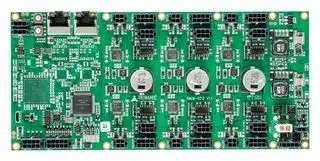
Illustrative purposes only

TMCM-6212-TMCL
Stepper Motor Driver, 2-Phase, 6-Axis, 1.1A, 24V DC Output, TMCL Firmware
⚠️ Reference pricing provided. In case of supply shortages, we will connect you with our trusted procurement partners to ensure your project's continuity.
- Manufacturer: TRINAMIC / ANALOG DEVICES
- Product type: Stepper Motor Drives
- Supply Voltage Min:11V; Supply Voltage Max:35V; No. of Phases:Two Phase; Power Rating:-; Output Voltage Max:24V; Output Current:1.1A; Product Range:-; SVHC:No SVHC (27-Jun-2018)
- SVHC: No SVHC (04-Feb-2026)
- No. of Phases: Two Phase
- Product Range: TMCM StepRocker
- Output Current Max: 1.1A
- Supply Voltage Max: 35VDC
- Supply Voltage Min: 11VDC
- Control / Drive Type: 6-Axis Controller / Driver Module
| Delivery and price | |
|---|---|
| Units per pack | 1 |
| Price | 433.28 € |
| Current stock | 10+ |
| Lead time | 30 days |
Datasheet

**MODULES FOR** **`STEPPER MOTORS MODULES`**
## **Hardware Version V 1.10**
## **HARDWARE MANUAL**
+
**==> picture [219 x 122] intentionally omitted <==**
**----- Start of picture text -----**<br>
eo ae! 7 ‘: On j OF ; i Hj<br>= ee eo a em<br>gel TR) nical leerCy dere<br>°“BESEMSEESEH ce SS (Gaeei (GSD (eee tue SORES<br>**----- End of picture text -----**<br>
**==> picture [4 x 4] intentionally omitted <==**
**----- Start of picture text -----**<br>
+<br>**----- End of picture text -----**<br>
## **TMCM-6212 TMCM-6213**
**`6-Axes Stepper Controller / Driver Up-to 1.1A RMS / 24V DC Encoder / HOME / STOP 4x analog / digital inputs 4x digital outputs Brake chopper support CAN, RS485, USB (TMCM-6212) EtherCAT™, USB (TMCM-6213)`**
+ +
TRINAMIC Motion Control GmbH & Co. KG Hamburg, Germany
**www.trinamic.com**
TMCM-6212, TMCM-6213 Hardware Manual (V0.91 / 2017-MAR-01)
2
## **Table of contents**
|1|Life support policy ....................................................................................................................................................... 3|Life support policy ....................................................................................................................................................... 3|
|---|---|---|
|2|Features ........................................................................................................................................................................... 4||
|3|Order codes .................................................................................................................................................................... 5||
|4|Mechanical and Electrical Interfacing ..................................................................................................................... 6||
||4.1|Dimensions and Mounting Holes ................................................................................................................... 6|
||4.2|Board mounting considerations ...................................................................................................................... 7|
|5|Connectors of TMCM-6212 and TMCM-6213 ........................................................................................................... 8||
||5.1|TMCM-6212 Interface Brick ................................................................................................................................ 8|
||5.1.1|RS485 connector ............................................................................................................................................ 9|
||5.1.2|CAN connector ................................................................................................................................................ 9|
||5.1.3|USB connector .............................................................................................................................................. 10|
||5.1.4|Input connector ........................................................................................................................................... 10|
||5.1.5|Output connector ......................................................................................................................................... 11|
||5.2|TMCM-6213 Interface Brick .............................................................................................................................. 11|
||5.2.1|EtherCAT™ connector ................................................................................................................................. 12|
||5.2.2|USB connector .............................................................................................................................................. 12|
||5.2.3|Input connector ........................................................................................................................................... 12|
||5.2.4|Output connector ......................................................................................................................................... 13|
||5.3|TMCM-6212 + TMCM-6213 Driver Brick .......................................................................................................... 14|
||5.3.1|Motor connector........................................................................................................................................... 14|
||5.3.2|REF / HOME connector ................................................................................................................................ 15|
||5.3.3|Encoder connector....................................................................................................................................... 15|
||5.4|TMCM-6212 + TMCM-6213 Power supply Brick ........................................................................................... 16|
||5.4.1|Power connector .......................................................................................................................................... 17|
||5.4.2|Control connector ........................................................................................................................................ 17|
||5.4.3|Resistor connector ....................................................................................................................................... 18|
||5.5|Power supply ...................................................................................................................................................... 18|
||5.6|RS485 ..................................................................................................................................................................... 18|
||5.7|CAN ........................................................................................................................................................................ 20|
||5.7.1|CAN adapter .................................................................................................................................................. 21|
||5.8|General purpose outputs OUT0..3 ................................................................................................................. 22|
|6|Motor driver current .................................................................................................................................................. 23||
|7|On Board LEDs............................................................................................................................................................. 24||
||7.1|Power supply brick ............................................................................................................................................ 24|
||7.2|TMCM-6212 Interface Brick .............................................................................................................................. 24|
||7.3|TMCM-6213 Interface Brick .............................................................................................................................. 25|
|8|Reset to Factory Default ........................................................................................................................................... 25||
|9|Operational ratings .................................................................................................................................................... 26||
|10 TMCM-6212 Functional Description ........................................................................................................................ 27|||
|11 TMCM-6213 Functional Description ........................................................................................................................ 28|||
|12 Revision History .......................................................................................................................................................... 29|||
||12.1|Document revision ............................................................................................................................................ 29|
||12.2|Hardware revision ............................................................................................................................................. 29|
|13 References..................................................................................................................................................................... 29|||
Copyright © 2016, 2017 TRINAMIC Motion Control GmbH & Co. KG
TMCM-6212, TMCM-6213 Hardware Manual (V0.91 / 2017-MAR-01)
3
## **1 Life support policy**
TRINAMIC Motion Control GmbH & Co. KG does not authorize or warrant any of its products for use in life support systems, without the specific written consent of TRINAMIC Motion Control GmbH & Co. KG.
Life support systems are equipment intended to support or sustain life, and whose failure to perform, when properly used in accordance with instructions provided, can be reasonably expected to result in personal injury or death.
- © TRINAMIC Motion Control GmbH & Co. KG 2016, 2017
Information given in this data sheet is believed to be accurate and reliable. However neither responsibility is assumed for the consequences of its use nor for any infringement of patents or other rights of third parties, which may result from its use.
Specifications are subject to change without notice.
Copyright © 2016, 2017 TRINAMIC Motion Control GmbH & Co. KG
TMCM-6212, TMCM-6213 Hardware Manual (V0.91 / 2017-MAR-01)
4
## **2 Features**
The TMCM-6212 / TMCM-6213 is a six axes controller/driver module for 2-phase bipolar stepper motors with separate encoder (differential) and HOME / STOP switch inputs for each axis. CAN, RS485 and USB (Micro-USB) interfaces are available on the TMCM-6212 and EtherCAT™ together with USB (Micro-USB) on the TMCM-6213 for communication. Furthermore the modules offer four analog / digital inputs and four digital outputs together with a brake chopper unit (supporting an external brake resistor) for supply voltage limitation when energy is fed back into the supply rail.
## **MAIN CHARACTERISTICS**
## **Motion controller**
- Motion profile calculation in real-time (supporting linear and sixPoint™ ramps)
- On the fly alteration of motor parameters (e.g. position, velocity, acceleration)
- Dedicated HOME + STOP switch inputs (internal pull-ups)
- High performance microcontroller for overall system control and communication protocol handling
## **Bipolar stepper motor driver**
- Up to 256 microsteps per full step
- High-efficient operation, low power dissipation
- Dynamic current control
- Integrated protection
- stealthChop™ for quiet operation and smooth motion
- dcStep™ feature for load dependent speed control
- stallGuard2™ feature for stall detection
- coolStep™ feature for reduced power consumption and heat dissipation
## **Interfaces**
- TMCM-6212: CAN + RS485
- TMCM-6213: EtherCAT™
- USB full speed (12Mbit/s) device interface (Micro-USB)
- Differential encoder input per motor axis (6x)
- HOME, STOP_L, STOP_R switch inputs with internal pull-ups per motor axis (6x)
- 4 general purpose analog inputs (0..10V) or digital inputs (accept +24V signals)
- 4 general purpose digital outputs (open-drain)
## **Software**
- TMCL™ remote (direct mode) and standalone operation with memory for up to 1024 TMCL commands
- TMCM-6212: CANopen firmware available
- TMCM-6213: CoE (CANopen over EtherCAT™) firmware available
## **Electrical data**
- Supply voltage: nom. +12V and +24V with +11V … +35V supply voltage operating range
- Motor current: up to 1.1A RMS (programmable)
## **Mechanical data**
- Board size: 215mm x 100mm, overall height 21mm max. (incl. pcb but, without mating connectors and cables)
- 12x M3 mounting holes (optional)
_Please see separate TMCM-6212 / TMCM-6213 Software / Firmware documentation for additional information regarding programming and communication protocol._
Copyright © 2016, 2017 TRINAMIC Motion Control GmbH & Co. KG
TMCM-6212, TMCM-6213 Hardware Manual (V0.91 / 2017-MAR-01)
5
## **3 Order codes**
The TMCM-6212 unit is available with two different firmware options:
|Order code|Description|Size of unit|
|---|---|---|
|TMCM-6212-TMCL|6-axes controller / driver up-to 1.1A RMS / +24V, CAN<br>+RS485+USB with standard TMCL firmware|<br>215mm x 100mm x 21mm|
|TMCM-6212-CANopen|6-axes controller / driver up-to 1.1A RMS / +24V, CAN<br>+ RS485+USB withCANopen firmware|<br>215mm x 100mm x 21mm|
## **Table 3.1: TMCM-6212 order code**
The TMCM-6213 unit is available as:
|Order code|Description|Size of unit|
|---|---|---|
|TMCM-6213-CoE|6-axes controller / driver up-to 1.1A RMS / +24V,<br>EtherCAT™ + USB with CANopen over EtherCAT™<br>firmware|<br> <br>215mm x 100mm x 21mm|
## **Table 3.2: TMCM-6213 order code**
A cable loom is available, also:
|Order code|Description|
|---|---|
|G4-CABLE|Cable loom for TMCM-6210/6211,**TMCM-6212/6213**, TMCM-3212/3213, TMCM-3214/3215,<br>TMCM-3312/3313 and TMCM-3314/3315. Contains:<br>-<br>1x cable loom for RS485 connector_(6212)_<br>-<br>1x standard CAT5 cable with 2x RJ45 for CAN / EtherCAT_(6212/6213)_<br>-<br>1x RJ45-2-DSUB_G4_V10 adapter (for CAN RJ45 <-> D-SUB translation)_(6212)_<br>-<br>1x Micro-USB cable_(6212/6213)_<br>-<br>1x cable loom for INPUTs connector_(6212/6213)_<br>-<br>1x cable loom for OUTPUTs connector_(6212/6213)_<br>-<br>6x cable loom for MOTOR connector (small)_(6212/6213)_<br>-<br>3x cable loom for MOTOR connector (big)<br>-<br>6x cable loom for ENCODER connector_(6212/6213)_<br>-<br>6x cable loom for REF / HOME connector_(6212/6213)_<br>-<br>1 cable loom for POWER connector (small)_(6212/6213)_<br>-<br>1x cable loom for POWER connector (big)<br>-<br>1x cable loom for CONTROL connector_(6212/6213)_<br>-<br>1xcableloom for RESISTORconnector_(6212/6213)_|
_Please note: there is one cable loom available for a complete family of modules in order to speed-up initial setup of these modules. The family consists of these currently planned / available modules: TMCM-6210/6211, TMCM6212/6213, TMCM-3212/3213, TMCM-3214/3215, TMCM-3312/3313 and TMCM-3314/3315. Not all cables are required for all modules – some cable will fit or will be helpful for some modules, only. Module numbers in parenthesis behind each cable in the table above indicate whether the particular part of the cable loom can be used with the TMCM-6212 and / or TMCM-6213._
Copyright © 2016, 2017 TRINAMIC Motion Control GmbH & Co. KG
TMCM-6212, TMCM-6213 Hardware Manual (V0.91 / 2017-MAR-01)
6
## **4 Mechanical and Electrical Interfacing**
## **4.1 Dimensions and Mounting Holes**
The dimensions of the TMCM-6212 and TMCM-6213 controller/driver board are approx. 215mm x 100mm x 21mm. Maximum component height (height above PCB level) without mating connectors is around 17mm above PCB level and 2mm below PCB level. There are 12 mounting holes for M3 screws (3.2mm diameter) altogether for mounting the PCB.
**Figure 4.1 Dimension of TMCM-6212 / TMCM-6213 and position of mounting holes**
Please note: TMCM-6212 and TMCM-6213 share the same PCB with different assembly options regarding the interface section. Dimensions, mounting holes and board mounting considerations (see chapter below) are the same for both boards.
Copyright © 2016, 2017 TRINAMIC Motion Control GmbH & Co. KG
TMCM-6212, TMCM-6213 Hardware Manual (V0.91 / 2017-MAR-01)
7
## **4.2 Board mounting considerations**
The TMCM-6212 / TMCM-6213 offer 12 metal plated mounting holes. One hole (lower right) is connected to onboard system ground (connected to power supply input ground) via 1M (500VDC) || 1nF (1kV). The same combination or resistor and capacitor is used for connecting the RJ45 shield ground (connector enclosure) to power supply input ground (see figure 4.1).
**==> picture [372 x 225] intentionally omitted <==**
**----- Start of picture text -----**<br>
1M 1nF 1M 1nF<br>n.c. n.c. n.c. n.c. n.c. n.c.<br>—<br>© + met ‘ | @: F s i! r fe wee @ve. @<br>oe ji 0 bd | oa | aoh asa p00 008;<br>kamen ‘Ee }; hs bE ie Py i LS ed 1 er | Pi<br>mn .Ala crab4) iatoeoomaeaaal"4=r| eft.aa82. tue. G2 : .a2. if3| aeito BicalI ve rv" Hf<br>a See ee were nasrite eterCaeF eelSegaog RE res Leref-sF Bi BY,?yu ee Ue Asiereraeay abaa.:yu be ee 4 hres:ieedaore aBa ae<br>= MAYnl asSR BiTHEY ew ft4 haeaat feHaEi Suuft)aera eefaee orn?EESBic:Nae ateee | |Eeaa Bap BleccesVee ele pesw 00<br>WY) as cere inane! a {Femme ay Bsi Weme ol<br>vO t |<br>soniho 38,owe Ssraylesip4 |pindgtetei. SeaI |cs]BE (5ame asaEEEOfBee Sietensyos OyXXOy trerdecenesESEiECr fore tay 3) rauCaeireDy A» Diesfen ee|= ee{5 es tite eereeeoder, (ay<br>aameOe CLOUIXIER ICRIHES “75.ae, | Bmw.e/a pe e t ute Ff A 5 i Se 343 bie iE - Shenton fi Be Z ae ses | (Hg £7 om<br>Pere pio ceusrulian ar bE 2. 3a Lo Dae — Dae441 « \ ame FI RS<br>mie<br>Fckcys) Restiase vee re a eaeceniininia Coen TRINAMIC 432 TMCM-6212 V1. ‘cpm Boe Shas<br>H = eae Tan of ear<br>ee SSBR [hah,] alee [Pee] [osha] pers [g] Wy) OAsSees tdBp ee?- Sct=e de < |i<br>ey \ tS aAeAs, os: 8 tt 19 Bej {I 7.<br>er ence het)Amaia lB g \ cat ae F z G<br>pASapa$ esaese‘2dhePa | femgg e:ethaeei = _ a) F‘ See Fy| eee ) q sas) | Paeeey e;sme oe<br>n.c. n.c. n.c. n.c. n.c.<br>1M I 1nF<br>**----- End of picture text -----**<br>
## **Figure 4.2 TMCM-6212 / TMCM-6213 mounting hole connections**
All other mounting holes are electrically isolated. Please note that not all holes have to be used for mounting the pcb. At least the mounting holes in all four corners and two in the middle (6 altogether) should be used to ensure adequate support of the pcb when inserting / removing connectors in order to avoid significant bending of the pcb.
In any case: please remove / attach mating connectors carefully – supporting the pcb if necessary!
Copyright © 2016, 2017 TRINAMIC Motion Control GmbH & Co. KG
TMCM-6212, TMCM-6213 Hardware Manual (V0.91 / 2017-MAR-01)
8
## **5 Connectors of TMCM-6212 and TMCM-6213**
The TMCM-6212 and TMCM-6213 are two members of a new family of modules with a modular architecture composed of so called “bricks”.
The TMCM-6212 and TMCM-6213 consist of one interface brick, three dual-axes stepper motor controller / driver bricks and one supply brick. With the TMCM-6212 the interface brick offers CAN and RS485 interfaces while with the TMCM-6213 the EtherCAT™ option is assembled instead. All other bricks are the same for both modules.
**==> picture [385 x 234] intentionally omitted <==**
**----- Start of picture text -----**<br>
Motor 1 Motor 3 Motor 5<br>he | = | on ie *—— U Jo<br>_<br>| aha. ¥: 222. 93 ot ty Ei<br>EP See Po . Ae Pie ai eres al Y<br>SS ees| cee. ie SEY Le wa £4 Boag a 54 a we ee<br>a {| Wisted ear Meshal , £4 i). Me ie<br>Grin POE |ei ‘cj Ce at Me 0) eh a ee |e wee eres<br>SS) ee eia CEE ane ay aN ; ‘iets<br>= LNSalore eis AcoSa AeC) OD halie te P ¥ DD) areaghe 2 _ (4) Ph paneFret if , Oss iu,Bow<br> sae is. | Be a a ae}! sug | te bee 3! Pa Say pm or 5 a Fha<br>an |ae ? Ma oh a ae 7° aa |<br>ed (ShpoA geSscent Aor EP Tape!2) (p34 ene Te | Ar= 3 oaey vi =are3 ew « SS feeu —sh<br>:} =e 75 2 # 5 | Fe P ey ‘<br>2077) ue es ee is + ss 2 im +e v1 | tem dl : 5 wonee<br>ey Uses Sar ee g we a ae: mr a; ip<br>ad lashed bes 2 sae “f° BF cpa" 8 | me k oa<br>agisd i + 4 aRabT ri zat is”& 2a i: FFr<br>al eee _<br>~~ Be gf E780550 Py | a a" Motor 0 q — emits Motor 2 a. et A ae Motor 4 4 _<br>Interface Brick Driver Brick Driver Brick Driver Brick Supply Brick<br>**----- End of picture text -----**<br>
**Figure 5.1 different bricks used for the TMCM-6212 / TMCM-6213**
## **5.1 TMCM-6212 Interface Brick**
The interface brick of the TMCM-6212 offers RS485, CAN and USB interfaces for communication, four general purpose analog inputs (which can be used as digital inputs as well) and four open-drain outputs.
**==> picture [372 x 192] intentionally omitted <==**
**----- Start of picture text -----**<br>
RS485 CAN<br>connector (2x) a:*- ] connector (2x)<br>1 GND eolle~ 3 1 | 1 CAN_H<br>23 RS485+RS485- e 1 H eo 3 Gay sas |. Bl=OC) 8 ssO8O 1 slaaleemetal 8 [Oy] 1 | 23 CAN_LGND<br>enh one PTET uitertiy(2 alae 4 n.c.<br>5 n.c.<br>ratte gee ALU<br>6 n.c.<br>USB (MicroUSB) W gather jy, it 7 n.c.<br>connector ea ae cy [|] Ei a9 8 n.c.<br>ae f =i]_fE) EL HN<br>eye ls Input connector<br>Output connector 1 +24V_FUSE 6 GND<br>1 OUT0 5 +24V_FUSE 2 AIN0 7 GND<br>2 OUT1 6 +24V_FUSE 3 AIN1 8 GND<br>3 OUT2 7 +24V_FUSE eo Bl 8 5 nt) misntenicnte®, 10 6 EGE 4 4 AIN2 9 GND<br>4 OUT3 8 +24V_FUSE e@ @;.e)..eee) 4 1 ee 5 C) 1 aeraat 5 AIN3 10 GND<br>aa |a<br>**----- End of picture text -----**<br>
**Figure 5.2 TMCM-6212 interface brick**
Copyright © 2016, 2017 TRINAMIC Motion Control GmbH & Co. KG
TMCM-6212, TMCM-6213 Hardware Manual (V0.91 / 2017-MAR-01) 9 Connector and mating connector overview: Label Connector type Mating connector type RS485 Molex MicroFit™, Molex MicroFit™, 436500315 Housing: 43645-0300 1x4 pin header, 3mm pitch Contacts: 43030-0007 CAN e.g. Standard CAT 5 / CAT 5e RJ45 plug connector cables may be used USB Micro-USB connector, type B Standard Micro-USB (USB device interface) Inputs Molex MicroFit™, Molex MicroFit™, 430451012 Housing: 43025-1000 2x5 pin header, 3mm pitch Contacts: 43030-0007 Outputs Molex MicroFit™, Molex MicroFit™, 430450812 Housing: 43025-0800 ~~==~~ 2x4 pin header, 3mm pitch Contacts: 43030-0007 **Table 5.1 TMCM-6212 interface brick: connectors and mating connectors 5.1.1 RS485 connector**
There are two RS485 connectors on the board with the same pin assignment – pins directly connected to each other. The second connector may be used for attaching a bus termination resistor to the RS485 bus (there is no termination resistor on-board) or for further distribution of the RS485 bus signals to other RS485 communication nodes while maintaining a proper bus structure.
A three pin Molex MicroFit™ connector (Molex part no. 436500315) is used for RS485 connection. Mating connector housing e.g. Molex 43645-0300, contacts Molex 43030-0007. Please note that there are alternative options available from Molex for both, housing and contacts.
|1<br>3|**Pin**|**Label**|**Direction**|**Description**|
|---|---|---|---|---|
||1|GND|Power|Supplyand signalground|
||2|RS485+|Bi-directional|RS485interface,diff. signal (non-inverting)|
||3|RS485-|Bi-directional|RS485interface,diff signal (inverting)|
**Table 5.1: Interface Brick: RS485 connector**
## **5.1.2 CAN connector**
There are two CAN connectors on the board with the same pin assignment – pins directly connected to each other. The second one may be used for attaching a bus termination resistor to the RS485 bus (there is no termination resistor on-board) or for further distribution of the CAN bus signals to other CAN nodes while maintaining a proper bus structure.
A standard RJ45 plug connector is used for CAN communication. Standard CAT cables (e.g. CAT 5, non-crossing) might be used for connection. Pin assignment of the RJ45 is based on the CiA 303-1 recommendation.
|1<br>8|**Pin**|**Label**|**Direction**|**Description**|
|---|---|---|---|---|
||1|CAN_H|Bi-Directional|CAN interface,diff signal (non-inverting)|
||2|CAN_L|Bi-directional|CAN interface,diff signal (inverting)|
||3|GND|Power|Supplyand signalground|
||4|n.c.|||
||5|n.c.|||
||6|n.c.|||
||7|n.c.|||
||8|n.c.|||
**Table 5.2 Interface Brick: CAN connector**
Copyright © 2016, 2017 TRINAMIC Motion Control GmbH & Co. KG
TMCM-6212, TMCM-6213 Hardware Manual (V0.91 / 2017-MAR-01)
10
## **5.1.3 USB connector**
The TMCM-6212 / TMCM-6213 offers a Micro USB connector (Type B, device interface) for communication. The USB interface supports USB high speed communication (12Mbit/s). With USB attached the digital logic part of the TMCM-6212 / TMCM-6213 will be supplied via USB (USB powered mode) if there is no main supply available. This mode may be used for firmware-updates, TMCL-program download or parameter settings etc. (requires USB connection, only). Please note that in USB stand-alone mode (main board supply available) the board might still draw current from the USB supply – depending on the voltage level of the USB +5V and the on-board generated +5V.
## **5.1.4 Input connector**
The TMCM-6212 / TMCM-6213 offer four analog inputs (nom. 0..10V range) which may be used as digital inputs, also (+24V tolerant).
The four inputs are available via one 10 pin Molex MicroFit™ connector (Molex part no. 430451012). Mating connector housing e.g. Molex 43025-1000, contacts Molex 43030-0007. Please note that there are alternative options available from Molex for both, mating housing and contacts.
|1<br>5<br>6<br>10<br>a ©|**Pin**|**Label**|**Direction**|**Description**|
|---|---|---|---|---|
||1|+24V_FUSE|Power output|Connected via fuse (polyfuse) to power supply input<br>(+24V_LOGIC supply input on power control connector).<br>Max. output current (together with all +24V_FUSE supply<br>outputs on output connector: 500mA / polyfuse<br>protected)|
||2<br>~~a~~|AIN0|Input|Analoginput channel 0 (nom. 0..10V)|
||3<br>~~a~~<br>~~A~~|AIN1<br>~~a~~|Input|Analoginput channel 1 (nom. 0..10V)|
||4<br> ~~A ~~<br>~~a~~|AIN2<br> ~~a~~|Input|Analoginput channel 2 (nom. 0..10V)|
||5<br>~~a~~<br>~~a~~|AIN3|Input|Analoginput channel3(nom. 0..10V)|
||6<br>~~a~~<br>~~a~~|GND|Power|Supplyand signalground|
||7<br>~~a~~<br>~~a~~|GND|Power|Supplyand signalground|
||8<br>~~a~~<br>~~a~~|GND|Power|Supplyand signalground|
||9<br>~~a~~<br>~~a~~|GND|Power|Supplyand signalground|
||10<br>~~a~~<br>~~a~~|GND|Power|Supplyand signalground|
**Table 5.3: Interface Brick: Input connector**
Copyright © 2016, 2017 TRINAMIC Motion Control GmbH & Co. KG
TMCM-6212, TMCM-6213 Hardware Manual (V0.91 / 2017-MAR-01)
11
## **5.1.5 Output connector**
The TMCM-6212 / TMCM-6213 offer four digital outputs (open-drain). The four outputs are available via one 8 pin Molex MicroFit™ connector (Molex part no. 43045-0812). Mating connector housing e.g. Molex 43025-0800, contacts Molex 43030-0007. Please note that there are alternative options available from Molex for both, mating housing and contacts.
|1<br>4<br>5<br>8<br>EIA!<br>oja|g/a<br>O™O|**Pin**|**Label**|**Direction**|**Description**|
|---|---|---|---|---|
||1|OUT0|Output|Open-drain output|
||2|OUT1|Output|Open-drain output|
||3|OUT2|Output|Open-drain output|
||4|OUT3|Output|Open-drain output|
||5|+24V_FUSE|Power output|Connected via fuse (polyfuse) to power supply input<br>(+24V_LOGIC supply input on power control connector).<br>Max. output current (together with all +24V_FUSE supply<br>outputs on output connector: 500mA / polyfuse<br>protected)|
||6|+24V_FUSE|Power output|Connected via fuse (polyfuse) to power supply input<br>(+24V_LOGIC supply input on power control connector).<br>Max. output current (together with all +24V_FUSE supply<br>outputs on output connector: 500mA / polyfuse<br>protected)|
||7|+24V_FUSE|Power output|Connected via fuse (polyfuse) to power supply input<br>(+24V_LOGIC supply input on power control connector).<br>Max. output current (together with all +24V_FUSE supply<br>outputs on output connector: 500mA / polyfuse<br>protected)|
||8|+24V_FUSE|Power output|Connected via fuse (polyfuse) to power supply input<br>(+24V_LOGIC supply input on power control connector).<br>Max. output current (together with all +24V_FUSE supply<br>outputs on output connector: 500mA / polyfuse<br>protected)|
**Table 5.4: Interface Brick: Output connector**
## **5.2 TMCM-6213 Interface Brick**
The interface brick of the TMCM-6213 offers EtherCAT™ and USB interfaces for communication, four general purpose analog inputs (which can be used as digital inputs as well) and four open-drain outputs.
**==> picture [339 x 182] intentionally omitted <==**
**----- Start of picture text -----**<br>
LINK LINK<br>IN OUT<br>EtherCAT<br>connector (2x)<br>1 TX+<br>8 1 8 1 2 TX-<br>3 RX+<br>4<br>5<br>6 RX-<br>USB (MicroUSB) 7<br>connector @ <Hie ee 8<br>fe. lee Input connector<br>Output connector 1 +24V_FUSE 6 GND<br>1 OUT0 5 +24V_FUSE (etepoke 2...utBealeIBO) 2 AIN0 7 GND<br>2 OUT1 6 +24V_FUSE 3 AIN1 8 GND<br>3 OUT2 7 +24V_FUSE 8 5 10 6 4 AIN2 9 GND<br>4 OUT3 8 +24V_FUSE 4 1 5 1 5 AIN3 10 GND<br>**----- End of picture text -----**<br>
**Figure 5.3 TMCM-6213 interface brick**
Copyright © 2016, 2017 TRINAMIC Motion Control GmbH & Co. KG
TMCM-6212, TMCM-6213 Hardware Manual (V0.91 / 2017-MAR-01)
12
Connector and mating connector overview:
|Label|Connector type|Mating connector type|
|---|---|---|
|EtherCAT™|RJ45 plug connector|e.g. Standard CAT 5 / CAT 5e<br>cables suitable for 100Mbit/s<br>Ethernet|
|USB|Micro-USB connector, type B<br>(USB device interface)|Standard Micro-USB|
|Inputs|Molex MicroFit™, 43045-1012<br>2x5 pin header, 3mm pitch|Molex MicroFit™,<br>Housing: 43025-1000<br>Contacts:43030-0007|
|Outputs|Molex MicroFit™, 43045-0812<br>2x4 pin header, 3mm pitch|Molex MicroFit™,<br>Housing: 43025-0800<br>Contacts:43030-0007|
**Table 5.5: TMCM-6213 interface brick: connectors and mating connectors**
## **5.2.1 EtherCAT™ connector**
There are two EtherCAT™ connectors on the board – one for LINK IN (towards / coming from EtherCAT™ master) and one for LINK OUT (for connecting further slaves) connection.
A standard RJ45 plug connector (as used for 10/100Mbit/s Ethernet) is used for EtherCAT™ communication. Standard CAT cable suitable for 100Mbit/s Ethernet (e.g. CAT 5 / 5e etc.) might be used for connection. The PHYs used on the TMCM-6213 support auto MDI-X – therefore, TX and RX signals on the connector might be exchanged – e.g. cables with straight-through pin-assignment can be used.
|1<br>8|**Pin**|**Label**|**Direction**|**Description**|
|---|---|---|---|---|
||1|TX+|Output|Transmit data output,differential,non-inverting|
||2|TX-|Output|Transmit data output,differential,inverting|
||3|RX+|Input|Receive data input,differential,non-inverting|
||4||||
||5||||
||6|RX-|Input|Receive data input,differential,inverting|
||7||||
||8||||
**Table 5.6: TMCM-6213 Interface Brick: EtherCAT™ connector**
## **5.2.2 USB connector**
The TMCM-6212 / TMCM-6213 offers a Micro USB connector (Type B, device interface) for communication. The USB interface supports USB high speed communication (12Mbit/s). With USB attached the digital logic part of the TMCM-6212 / TMCM-6213 will be supplied via USB (USB powered mode) if there is no main supply available. This mode may be used for firmware-updates, TMCL-program download or parameter settings etc. (requires USB connection, only). Please note that in USB stand-alone mode (main board supply available) the board might still draw current from the USB supply – depending on the voltage level of the USB +5V and the on-board generated +5V.
## **5.2.3 Input connector**
The TMCM-6212 / TMCM-6213 offer four analog inputs (nom. 0..10V range) which may be used as digital inputs, also (+24V tolerant).
The four inputs are available via one 10 pin Molex MicroFit™ connector (Molex part no. 430451012). Mating connector housing e.g. Molex 43025-1000, contacts Molex 43030-0007. Please note that there are alternative options available from Molex for both, mating housing and contacts.
Copyright © 2016, 2017 TRINAMIC Motion Control GmbH & Co. KG
TMCM-6212, TMCM-6213 Hardware Manual (V0.91 / 2017-MAR-01)
13
|1<br>5<br>6<br>10<br>es|**Pin**|**Label**|**Direction**|**Description**|
|---|---|---|---|---|
||1|+24V_FUSE|Power output|Connected via fuse (polyfuse) to power supply input<br>(+24V_LOGIC supply input on power control connector).<br>Max. output current (together with all +24V_FUSE supply<br>outputs on output connector: 500mA / polyfuse<br>protected)|
||2<br>~~a~~|AIN0|Input|Analoginput channel 0 (nom. 0..10V)|
||3|AIN1|Input<br>~~Ge~~|Analoginput channel 1 (nom. 0..10V)|
||4<br>~~a~~|AIN2|Input<br>~~Ge~~|Analoginput channel 2 (nom. 0..10V)|
||5<br>~~a~~|AIN3|Input|Analoginput channel3(nom. 0..10V)|
||6<br>~~a~~|GND|Power|Supplyand signalground|
||7<br>~~a~~|GND|Power|Supplyand signalground|
||8<br>~~a~~<br>~~a~~|GND<br>~~es~~|Power|Supplyand signalground|
||9<br>~~a~~<br>~~a~~|GND<br>~~es~~|Power|Supplyand signalground|
||10<br>~~a~~|GND<br>~~es~~|Power|Supplyand signalground|
**Table 5.7: Interface Brick: Input connector**
## **5.2.4 Output connector**
The TMCM-6212 / TMCM-6213 offer four digital outputs (open-drain). The four outputs are available via one 8 pin Molex MicroFit™ connector (Molex part no. 43045-0812). Mating connector housing e.g. Molex 43025-0800, contacts Molex 43030-0007. Please note that there are alternative options available from Molex for both, mating housing and contacts.
|1<br>4<br>5<br>8<br>PIECE)|**Pin**<br>~~a~~|**Label**|**Direction**|**Description**|
|---|---|---|---|---|
||1<br>~~a~~|OUT0|Output|Open-drain output channel 0|
||2<br>~~a~~<br>~~a~~<br>~~a~~|OUT1<br>~~es~~|Output|Open-drain output channel 1|
||3<br>~~a~~<br>~~a~~<br>~~a~~|OUT2<br>~~es~~|Output|Open-drain output channel 2|
||4<br>~~a~~|OUT3<br>~~es~~|Output|Open-drain output channel3|
||5|+24V_FUSE|Power output|Connected via fuse (polyfuse) to power supply input<br>(+24V_LOGIC supply input on power control connector).<br>Max. output current (together with all +24V_FUSE supply<br>outputs on output connector: 500mA / polyfuse<br>protected))|
||6|+24V_FUSE|Power output|Connected via fuse (polyfuse) to power supply input<br>(+24V_LOGIC supply input on power control connector).<br>Max. output current (together with all +24V_FUSE supply<br>outputs on output connector: 500mA / polyfuse<br>protected)|
||7|+24V_FUSE|Power output|Connected via fuse (polyfuse) to power supply input<br>(+24V_LOGIC supply input on power control connector).<br>Max. output current (together with all +24V_FUSE supply<br>outputs on output connector: 500mA / polyfuse<br>protected)|
||8|+24V_FUSE|Power output|Connected via fuse (polyfuse) to power supply input<br>(+24V_LOGIC supply input on power control connector).<br>Max. output current (together with all +24V_FUSE supply<br>outputs on output connector: 500mA / polyfuse<br>protected)|
**Table 5.8: Interface Brick: Output connector**
Copyright © 2016, 2017 TRINAMIC Motion Control GmbH & Co. KG
TMCM-6212, TMCM-6213 Hardware Manual (V0.91 / 2017-MAR-01)
14
## **5.3 TMCM-6212 + TMCM-6213 Driver Brick**
The driver brick of the TMCM-6212 and TMCM-6213 offers two outputs for bipolar stepper motors with up-to 1.1A RMS / 1.5A peak motor current (programmable), separate HOME + REFL and REFR inputs and encoder inputs (for incremental ABN encoders with differential signals) for each motor axes. Please note that due to sharing of hardware resources either REFL and REFR inputs or encoder inputs are available at a given point in time and may be used. The TMCM-6212 and TMCM-6213 offer three such driver bricks, supporting 6 stepper motors altogether.
**==> picture [303 x 200] intentionally omitted <==**
**----- Start of picture text -----**<br>
Motor connector T C 1 X 2 FXam 1 4 ) Encoder connector<br>WOOEO 3 4 5 e 8<br>1 3 REF / HOME connector<br>un. 72@n®@ 2 4<br>ile<br>REF / HOME connector<br>1 GND 4 +5V_OUT<br>mma uu 2 REFL 5 REFR<br>6 4 3 HOME 6 GND<br>3 1<br>Motor connector , di a OEO)<br>1 OA1 3 OA2 4 3 8 5 Encoder connector<br>—}—}}—¥§_ 2 OB1 4 OB2 CO [|S] 2 1 4 Omg 1 1 GND 5 +5V_OUT<br>2 ENC_A+ 6 ENC_A-<br>3 ENC_B+ 7 ENC_B-<br>4 ENC_N+ 8 ENC_N-<br>**----- End of picture text -----**<br>
**Figure 5.4 TMCM-6212 + TMCM-6213 Driver Brick**
|Label|Connector type|Mating connector type|
|---|---|---|
|Motor|Molex MicroFit Jr.™, 43045-0412<br>2x2 pin header, 3mm pitch|Molex MicroFit Jr.™,<br>Housing: 43025-0400<br>Contacts:43030-0007|
|REF / HOME|Molex MicroFit™, 43045-0612<br>2x3 pin header, 3mm pitch|Molex MicroFit™,<br>Housing: 43025-0600<br>Contacts:43030-0007|
|Encoder|Molex MicroFit™, 43045-0812<br>2x4 pin header, 3mm pitch|Molex MicroFit™,<br>Housing: 43025-0800<br>Contacts: 43030-0007|
**Table 5.9 TMCM-6212 and TMCM-6213 Driver brick: connectors and mating connectors**
## **5.3.1 Motor connector**
As there are two bipolar stepper motors supported per single driver brick there are also two motor connectors per brick.
Each motor (with two coils A + B and four connecting wires) can be connected via one 4 pin Molex MicroFit™ connector (Molex part no. 43045-0412). Mating connector housing e.g. Molex 43025-0400, contacts Molex 430300007. Please note that there are alternative options available from Molex for both, mating housing and contacts.
**==> picture [482 x 71] intentionally omitted <==**
**----- Start of picture text -----**<br>
Pin Label Direction Description<br>4 3 1 OA1 Output Motor coil A<br>OoO | |<br>oe 2 OB1 Output Motor coil B<br>wey 2 1 _ 3 OA2 —————E Output Motor coil A<br>4 ————————EEE OB2 Output Motor coil B<br>**----- End of picture text -----**<br>
**Table 5.10: Driver Brick: Motor connector**
Copyright © 2016, 2017 TRINAMIC Motion Control GmbH & Co. KG
TMCM-6212, TMCM-6213 Hardware Manual (V0.91 / 2017-MAR-01)
15
## **CAUTION**
## _**Do not connect or disconnect motor during operation!**_
Motor cable and motor inductivity might lead to voltage spikes when the motor is disconnected / connected while energized. These voltage spikes might exceed voltage limits of the driver MOSFETs and might permanently damage them. Therefore, always switch off and / or disconnect power supply before connecting / disconnecting the motor.
## **5.3.2 REF / HOME connector**
There are two REF / HOME connectors per single driver brick – one for each motor axis. HOME, REFL and / or REFR switches may be connected via one 6 pin Molex MicroFit™ connector (Molex part no. 43045-0612). Mating connector housing e.g. Molex 43025-0600, contacts Molex 43030-0007. Please note that there are alternative options available from Molex for both, mating housing and contacts.
|1<br>3<br>4<br>6<br>Bae|**Pin**<br>~~eG~~|**Label**<br>~~eG~~|**Direction**<br>~~eG~~|**Description**<br>~~eG~~|
|---|---|---|---|---|
||1|GND|Power|Supplyand signalground|
||2<br>~~r~~|REFL<br>~~r~~|Input<br>~~r~~|REF left / Left stop switch input. Internal pull-up (5k6) to<br>+5V. External switch to ground may be connected or up-<br>to+5Vpush-pullsignal.<br>~~re~~|
||3<br>~~r~~|HOME<br>~~r~~|Input<br>~~r~~|Home switch input. Internal pull-up (5k6) to +5V. External<br>switch to ground may be connected or up-to +5V push-<br>pull signal.<br>~~re~~|
||4|+5V_OUT|Power output|Connected to the on-board +5V auxiliary DC/DC converter.<br>All +5V_OUT power supply outputs together on the 6 REF<br>/ HOME and 6 Encoder connectors may draw up-to 1A<br>(e.g. 100mA per encoder and up-to 20mA per REF / HOME<br>switch).|
||5|REFR|Input|REF right / Right stop switch input. Internal pull-up (5k6)<br>to +5V. External switch to ground may be connected or<br>up-to+5Vpush-pullsignal.|
||6<br>~~ee~~|GND<br>~~ee~~|Power<br>~~ee~~|Supplyand signalground<br>~~ee~~|
## **Table 5.11: Driver Brick: REF / HOME connector**
## **5.3.3 Encoder connector**
There are two Encoder connectors per single driver brick – one for each motor axis. Incremental A/B/N encoders with differential encoder signals are supported. The TMCM-6212 / TMCM-6213 offer on-board differential line receivers (AM26LV32 or equivalent) with 120R termination resistor per differential signal pair. Differential encoder signals may be connected via one 8 pin Molex MicroFit™ connector (Molex part no. 43045-0812). Mating connector housing e.g. Molex 43025-0800, contacts Molex 43030-0007. Please note that there are alternative options available from Molex for both, mating housing and contacts.
Copyright © 2016, 2017 TRINAMIC Motion Control GmbH & Co. KG
TMCM-6212, TMCM-6213 Hardware Manual (V0.91 / 2017-MAR-01)
16
|1<br>4<br>5<br>8<br>allele)|**Pin**<br>~~a~~|**Label**<br>~~ae~~|**Direction**<br>~~ee~~|**Description**|
|---|---|---|---|---|
||1<br>~~a ~~<br>~~a~~|GND<br> ~~ae~~<br>~~ee~~|Power<br>~~ee~~<br>~~ee~~|Supplyand signalground|
||2<br>~~a~~<br>~~a~~|ENC_A+<br>~~ee~~|Input<br>~~ee~~|Differential input of encoder channel A,non-invertinginput|
||3<br>~~a~~<br>~~aee~~|ENC_B+<br>~~ee~~|Input<br>~~ee~~|Differential input of encoder channel B,non-invertinginput<br>~~ee~~|
||4<br>~~aee~~|ENC_N+<br>~~ee~~|Input<br>~~ee~~|Differential input of encoder null / zero channel, non-<br>invertinginput<br>~~ee~~|
||5<br>~~ee~~|+5V_OUT<br>~~ee ~~|Power<br>output<br> ~~ee~~|Connected to the on-board +5V auxiliary DC/DC converter.<br>All +5V_OUT power supply outputs together on the 6 REF /<br>HOME and 6 Encoder connectors may draw up-to 1A (e.g.<br>100mA per encoder and up-to 20mA per REF / HOME<br>switch).<br>~~ee~~|
||6<br>~~a~~|ENC_A-|Input|Differential input of encoder channel A,invertinginput|
||7<br>~~a~~|ENC_B-|Input|Differential input of encoder channel B,invertinginput|
||8|ENC_N-|Input|Differential input of encoder null / zero channel, inverting<br>input|
**Table 5.12: Driver Brick: Encoder connector**
## **5.4 TMCM-6212 + TMCM-6213 Power supply Brick**
The power supply brick of the TMCM-6212 and TMCM-6213 offers one main supply input via the Power connector, separate logic supply input as an option and a hardware driver stage enable input on the Control connector and connection for an external brake connector with the on-board brake chopper circuit.
**==> picture [233 x 101] intentionally omitted <==**
**----- Start of picture text -----**<br>
Power connector<br>1 GND<br>2 +24V<br>Control connector<br>Resistor connector<br>1 GND 2 1 2 1 1 +24V<br>2 +24V_LOGIC<br>2 Resistor<br>3 +24V_LOGIC Sie 4 oD 1<br>4 Enable<br>**----- End of picture text -----**<br>
**Figure 5.5: TMCM-6212 + TMCM-6213 Power supply Brick**
Connector and mating connector overview:
|Label|Connector type|Mating connector type|
|---|---|---|
|Power|Molex MiniFit Jr.™, 39-28-1023<br>1x2 pin header, 4.2mm pitch|Molex MiniFit Jr.™,<br>Housing: 39-01-2020<br>Contacts: 39-00-0039|
|Control|Molex MicroFit™, 43650-0415<br>1x4 pin header, 3mm pitch|Molex MicroFit™,<br>Housing: 43645-0400<br>Contacts: 43030-0007|
|Resistor|Molex MicroFit™, 43650-0215<br>2x4 pin header, 3mm pitch|Molex MicroFit™,<br>Housing: 43645-0200<br>Contacts:43030-0007|
**Table 5.13 TMCM-6212 and TMCM-6213 Power supply brick: connectors and mating connectors**
Copyright © 2016, 2017 TRINAMIC Motion Control GmbH & Co. KG
TMCM-6212, TMCM-6213 Hardware Manual (V0.91 / 2017-MAR-01)
17
## **5.4.1 Power connector**
A two pin Molex MiniFit Jr.™ connector (Molex part no. 39-28-1023) is available for power supply connection. Mating connector housing e.g. Molex 39-01-2020, contacts Molex 39-00-0039. Please note that there are alternative options available from Molex for both, housing and contacts.
|1<br>2|**Pin**|**Label**|**Direction**|**Description**|
|---|---|---|---|---|
||1|GND|Power|Supplyand signalground|
||2<br>~~re~~|+24V<br>~~re~~|Power supply<br>input<br>~~re~~|Power supply input. +12V … +24V +/- 10% regulated power<br>supply input. Supply input for all six motor driver stages<br>andlogic supply.<br>~~re~~|
## **Table 5.14: Power supply Brick: Power connector**
**CAUTION**
_**Always keep the power supply voltage (+24V) below the upper limit of 35V!** Otherwise the driver electronics will be seriously damaged. Especially, when the selected operating voltage is near the upper limit a regulated power supply is highly recommended._
_**Always keep the logic power supply voltage (+24V_LOGIC) above or equal to the main power supply!** Otherwise the on-board electronics (diode connection between +24V main power supply input and +24V logic supply input) might be seriously damaged._
## **5.4.2 Control connector**
A four pin Molex MicroFit™ connector (Molex part no. 436500415) is used for the driver stage enable signal and optional separate logic supply input. Mating connector housing e.g. Molex 43645-0400, contacts Molex 43030-0007. Please note that there are alternative options available from Molex for both, housing and contacts.
|1<br>4|**Pin**|**Label**|**Direction**|**Description**|
|---|---|---|---|---|
||1|GND|Power|Supplyand signalground|
||2|+24V_LOGIC|Power supply<br>input|Separate logic supply input. May be used in order to<br>keep digital / logic part alive while driver stage is not<br>supplied (Power supply input via Power connector either<br>switched off or disconnected).|
||3|+24V_LOGIC|Power supply<br>input|Same as Pin 2.|
||4<br>~~a~~|ENABLE<br>~~a~~|Input<br>~~a~~|Driver stage enable input (logic high). Maybe connected<br>to pin3/ +24V_LOGICinorderto enable driver.<br>~~a~~|
**Table 5.15: Power supply brick: Control connector**
## **CAUTION**
_**Always keep the digital logic power supply voltage (+24V_LOGIC) below the upper limit of 35V!** Otherwise the on-board electronics might be seriously damaged. Especially, when the selected operating voltage is near the upper limit a regulated power supply is highly recommended._
_**Always keep the logic power supply voltage (+24V_LOGIC) above or equal to the main power supply (on the Power supply connector)!** Otherwise the on-board electronics (diode connection between +24V main power supply input and +24V logic supply input) might be seriously damaged._
Copyright © 2016, 2017 TRINAMIC Motion Control GmbH & Co. KG
TMCM-6212, TMCM-6213 Hardware Manual (V0.91 / 2017-MAR-01)
18
## **5.4.3 Resistor connector**
The TMCM-6212 and TMCM-6213 offer a brake chopper in hardware for limiting supply voltage in case energy is fed back from motor / driver stage into the supply rail. A two pin Molex MicroFit™ connector (Molex part no. 43650-0215) is used for connecting an external brake resistor. Mating connector housing e.g. Molex 43645-0200, contacts Molex 43030-0007. Please note that there are alternative options available from Molex for both, housing and contacts.
|1<br>2|**Pin**|**Label**|**Direction**|**Description**|
|---|---|---|---|---|
||1|+24V|Power supply<br>input|Connected to power supply input of Power connector.|
||2|Resistor|Output|Brake chopper output. An external power resistor should<br>be connectedbetween Pin 1andPin 2ofthis connector.|
**Table 5.16: Power supply brick: Resistor connector**
## **5.5 Power supply**
For proper operation care has to be taken with regard to power supply concept and design. The TMCM-6212 / TMCM-6213 includes about 3000µF/50V of supply filter capacitors. In addition, the module includes a 33V suppressor diode for over-voltage protection. Nevertheless, it is important to make sure that supply voltage will not rise beyond the upper limit of +35V! Please note: during motor deceleration the driver stage might feedback energy from the motor into the supply rail and supply voltage might increase. In order to limit the supply voltage a brake chopper circuit has been included on the board. When activated in software and together with an external power resistor this circuit will limit the supply voltage.
**CAUTION** _**Always keep the power supply voltage (+24V) below the upper limit of 35V!** Otherwise the on-board electronics might be seriously damaged. Especially, when the selected operating voltage is near the upper limit a regulated power supply is highly recommended. In addition, the on-board brake chopper may be used together with an external power resistor connected to the Resistor connector in order to limit supply voltage._
_**Always keep the digital logic power supply voltage (+24V_LOGIC) below the upper limit of 35V!** Otherwise the on-board electronics might be seriously damaged. Especially, when the selected operating voltage is near the upper limit a regulated power supply is highly recommended._
_**Always keep the logic power supply voltage (+24V_LOGIC) above or equal to the main power supply (on the Power supply connector)!**_
_Otherwise the on-board electronics (diode connection between +24V main power supply input and +24V logic supply input) might be seriously damaged._ _**There is limited reverse polarity protection, only!**_
The module will short any reversed supply voltage.
## **5.6 RS485**
For remote control and communication with a host system the TMCM-6212 provides a two wire RS485 bus interface. For proper operation the following items should be taken into account when setting up an RS485 network:
1. _BUS STRUCTURE_ : The network topology should follow a bus structure as closely as possible. That is, the connection between each node and the bus itself should be as short as possible. Basically, it should be short compared to the length of the bus. The TMCM-6212 offers two connectors which are connected directly to each other and the on-board RS485 transceiver. Using both connectors for passing through the bus will help with keeping a proper bus topology.
Copyright © 2016, 2017 TRINAMIC Motion Control GmbH & Co. KG
TMCM-6212, TMCM-6213 Hardware Manual (V0.91 / 2017-MAR-01)
19
**==> picture [371 x 114] intentionally omitted <==**
**----- Start of picture text -----**<br>
Host<br>Slave Slave Slave<br>c:> node node node<br>1 n - 1 n<br>}<br>termination termination<br>resistor resistor<br>(120 Ohm) (120 Ohm)<br>RS485 keep distance as<br>short as possible<br>**----- End of picture text -----**<br>
**Figure 5.3: Bus structure**
2. _BUS TERMINATION_ : Especially for longer busses and/or multiple nodes connected to the bus and/or high communication speeds, the bus should be properly terminated at both ends. The TMCM-6212 does not integrate any termination resistor. Therefore, 120 Ohm termination resistors at both ends of the bus have to be added externally.
3. _NUMBER OF NODES_ : The RS485 electrical interface standard (EIA-485) allows up to 32 nodes to be connected to a single bus. The bus transceivers used on the TMCM-6212 units (SN65HVD1781D) have a significantly reduced bus load and allow a maximum of 255 units to be connected to a single RS485 bus using TMCL firmware. _Please note: usually it cannot be expected to get reliable communication with the maximum number of nodes connected to one bus and maximum supported communication speed at the same time. Instead, a compromise has to be found between bus cable length, communication speed and number of nodes._
_4. COMMUNICATION SPEED:_ The maximum RS485 communication speed supported by the TMCM-6212 hardware is 1Mbit/s. Factory default is 9600 bit/s. _Please see separate firmware manuals for information regarding other possible communication speeds below the upper limit in hardware._
5. _NO FLOATING BUS LINES:_ Avoid floating bus lines while neither the host/master nor one of the slaves along the bus line is transmitting data (all bus nodes switched to receive mode). Floating bus lines may lead to communication errors. In order to ensure valid signals on the bus it is recommended to use a resistor network connecting both bus lines to well defined logic levels.
There are actually two options which can be recommended: Add resistor (Bias) network on **one** side of the bus, only (120R termination resistor still at **both** ends):
**==> picture [379 x 138] intentionally omitted <==**
**----- Start of picture text -----**<br>
Slave Slave<br>node node +5V<br>n - 1 n<br>pull-up (680R)<br>termination RS485+ / RS485A termination<br>resistor resistor<br>(220R) RS485- / RS485B (120R)<br>pull-down (680R)<br>GND<br>**----- End of picture text -----**<br>
**Figure 4.4: Bus lines with resistor (Bias) network on one side, only**
Or add resistor (Bias) network at **both** ends of the bus (like Profibus™ termination):
Copyright © 2016, 2017 TRINAMIC Motion Control GmbH & Co. KG
TMCM-6212, TMCM-6213 Hardware Manual (V0.91 / 2017-MAR-01)
20
**==> picture [404 x 138] intentionally omitted <==**
**----- Start of picture text -----**<br>
Slave Slave<br>+5V node node +5V<br>n - 1 n<br>pull-up (390R) pull-up (390R)<br>termination RS485+ / RS485A termination<br>resistor resistor<br>(220R) RS485- / RS485B (220R)<br>pull-down (390R) pull-down (390R)<br>GND GND<br>**----- End of picture text -----**<br>
**Figure 4.5: Bus lines with resistor (Bias) network at both ends**
Certain RS485 interface converters available for PCs already include these additional resistors (e.g. USB-2485 with bias network at one end of the bus).
## **5.7 CAN**
For remote control and communication with a host system the TMCM-6212 provides a CAN bus interface. For proper operation the following items should be taken into account when setting up a CAN network:
1. _BUS STRUCTURE_ : The network topology should follow a bus structure as closely as possible. That is, the connection between each node and the bus itself should be as short as possible. Basically, it should be short compared to the length of the bus. The TMCM-6212 offers two connectors (RJ45) which are connected directly to each other and the on-board CAN transceiver. Using both connectors for passing through the bus will help with keeping a proper bus topology.
**==> picture [371 x 114] intentionally omitted <==**
**----- Start of picture text -----**<br>
Host<br>Slave Slave Slave<br>c:> node node node<br>1 n - 1 n<br>}<br>termination termination<br>resistor resistor<br>(120 Ohm) (120 Ohm)<br>CAN keep distance as<br>short as possible<br>**----- End of picture text -----**<br>
**Figure 5.6: CAN bus structure**
## 2. _BUS TERMINATION_ :
Especially for longer busses and/or multiple nodes connected to the bus and/or high communication speeds, the bus should be properly terminated at both ends. The TMCM-6212 does not integrate any termination resistor. Therefore, 120 Ohm termination resistors at both ends of the bus have to be added externally.
Copyright © 2016, 2017 TRINAMIC Motion Control GmbH & Co. KG
TMCM-6212, TMCM-6213 Hardware Manual (V0.91 / 2017-MAR-01)
21
## **5.7.1 CAN adapter**
As part of the cable loom for the TMCM-6212 (G4-CABLE) an adapter pcb is vailable (RJ45-2-DSUB_G4_V10) for making CAN bus connection via standard D-SUB connectors instead of the RJ45 available on the TMCM-6212. A standard e.g. CAT5 ethernet cable might be used to connect the RJ45 connector on the TMCM-6212 with the RJ45 connector on the adapter pcb. The D-SUB connector on the adapter pcb might then be used to connect further slaves or the master with CAN D-SUB connectors. Please make sure to maintain a proper bus structure while using the adapter pcb.
**Figure 5.6: RJ45-2-DSUB PCB top view**
**Figure 5.7: RJ45-2-DSUB schematic / connector pin assignment**
Copyright © 2016, 2017 TRINAMIC Motion Control GmbH & Co. KG
TMCM-6212, TMCM-6213 Hardware Manual (V0.91 / 2017-MAR-01)
22
## **5.8 General purpose outputs OUT0..3**
The TMCM-6212 and TMCM-6213 offer 4 open-drain (N-channel MOSFET) general purpose outputs available at the output connector of the interface brick part. The internal connection of the N-channel MOSFETs together with a flyback / freewheeling diode can be seen in figure 5.8. When activating the MOSFET the related output will be pulled low (sometimes called npn-style switch). Please note the internal fuse limiting the current that can be drawn from the output connector.
**==> picture [260 x 186] intentionally omitted <==**
**----- Start of picture text -----**<br>
TMCM-6212 / TMCM-6213<br>+24V_LOGIC<br>Polyfuse<br>0.5A/60V<br>5 1 OUT0<br>OUT1<br>OUT2 microcontroller<br>OUT3<br>8 4 GND<br>Output OUT0..3 with internal circuit<br>of OUT0 as example<br>**----- End of picture text -----**<br>
**Figure 5.8: General purpose output – internal circuit (simplified)**
Copyright © 2016, 2017 TRINAMIC Motion Control GmbH & Co. KG
TMCM-6212, TMCM-6213 Hardware Manual (V0.91 / 2017-MAR-01)
23
## **6 Motor driver current**
The stepper motor driver section of the TMCM-6212 + TMCM-6213 operates current controlled. The driver current may be programmed in software with 256 effective scaling steps in hardware up-to 1.1A RMS / 1.5A peak max. motor coil current.
_Motor current measured for one phase with max. current settings (100% e.g. “SAP 6, 0, 255”) and 256 microsteps:_
_CH1 (yellow): motor current [50mV / A]_
_**Motor current**_ In TMCL axis parameter 6 (motor run current) and 7 (motor standby current) can be used _**setting in**_ for motor current setting: _**software (TMC)**_
`SAP 6, 0, <value> // set run current`
`SAP 7, 0, <value> // set standby current`
For `<value>` numbers between 0 (minimum) and 255 (maximum) are supported. Motor current is scaled linearly up-to 1.1A RMS / 1.5A peak.
(read-out value with `GAP` instead of `SAP` . Please see separate TMCM-6212 / TMCM-6213 firmware / software manual for further information)
Copyright © 2016, 2017 TRINAMIC Motion Control GmbH & Co. KG
TMCM-6212, TMCM-6213 Hardware Manual (V0.91 / 2017-MAR-01)
24
## **7 On Board LEDs**
There are a number of LEDs on-board indicating status.
## **7.1 Power supply brick**
With the TMCM-6212 and TMCM-6213 two LEDs are available on the power supply brick part.
**==> picture [71 x 24] intentionally omitted <==**
**----- Start of picture text -----**<br>
+5V supply<br>+5V auxilliary supply<br>**----- End of picture text -----**<br>
**Figure 7.1: LEDs on power supply brick**
|**LED**|**Description**|
|---|---|
|+5V supply|+5V available from on-board DC/DC converter for supply of on-board digital circuit|
|+5V auxiliary supply|+5V auxiliary supply available (can be switched on/off in software). +5V_OUT on<br>REF/HOME and ENCODER connector.|
## **7.2 TMCM-6212 Interface Brick**
With the TMCM-6212 there are two LEDs (one green and one red) available. Both are connected to the on-board microcontroller and function is firmware dependent. With TMCL firmware the green LED is flashing slowly during operation. During firmware updates both LEDs are switched on.
**==> picture [43 x 23] intentionally omitted <==**
**----- Start of picture text -----**<br>
LED (red)<br>LED (green)<br>**----- End of picture text -----**<br>
**Figure 7.2: LEDs on TMCM-6212 interface brick**
Copyright © 2016, 2017 TRINAMIC Motion Control GmbH & Co. KG
TMCM-6212, TMCM-6213 Hardware Manual (V0.91 / 2017-MAR-01)
25
## **7.3 TMCM-6213 Interface Brick**
With the TMCM-6213 there are five LEDs available. Two LEDs are connected to the processor and three to the EtherCAT™ slave controller (ESC). In addition, one LED (ERROR) is connected to both, the microcontroller and the ESC.
**==> picture [89 x 71] intentionally omitted <==**
**----- Start of picture text -----**<br>
EtherCAT LINK IN<br>EtherCAT LINK OUT<br>EtherCAT RUN<br>ERROR<br>LED (green)<br>**----- End of picture text -----**<br>
**Figure 7.3: LEDs on TMCM-6213 interface brick**
|**LED**|**Description**|
|---|---|
|EtherCAT™ LINK IN|Signal LINK IN, connected to ESC|
|EtherCAT™ LINK OUT|Signal LINK OUT, connected to ESC|
|EtherCAT RUN|Indicatingstatus of EtherCAT state machine, connected to ESC|
|ERROR|Connected to microcontroller and ESC – indicatingError|
|LED (green)|Connected to microcontroller – flashingslowly duringnormal operation|
## **8 Reset to Factory Default**
For reset to factory default values please follow instructions below:
1. Switch OFF power supply.
2. Short two pads of programming connector pad-array (see figure 8.1).
3. Switch ON power supply (on-board LED should be flashing fast / faster than during normal operation). 4. Switch OFF power supply.
5. Remove short circuit.
**Figure 8.1 Reset to factory defaults (bottom view of pcb - interface brick end)**
Copyright © 2016, 2017 TRINAMIC Motion Control GmbH & Co. KG
TMCM-6212, TMCM-6213 Hardware Manual (V0.91 / 2017-MAR-01)
26
## **9 Operational ratings**
The operational ratings show the intended or the characteristic ranges and should be used as design values. _**In no case shall the maximum values be exceeded.**_
|**Symbol**|**Parameter**|**Min**|**Typ**|**Max**|**Unit**|
|---|---|---|---|---|---|
|+24V|Power supply voltage input|11|24|35|V|
|+24V_LOGIC|Power supply voltage for on-board digital /<br>logic (if supplied separately)|Same as<br>+24V<br>supply<br>input|||V|
|IPEAK|Motor coil current for sine wave**peak**<br>(chopper regulated, adjustable via software)|||1.5|A|
|IRMS|Continuous motor current (**RMS**)|||1.1|A|
|I+24V|Power supply current for driver||<< 6 x IRMS||A|
|TENV|Environmental temperature at 6x 1.1A RMS<br>motor current (no forced cooling)|-30**)||+40***)|°C|
## **Table 9.1: General operational ratings of the module**
_**) limited by test equipment. Operation down to -40°C can be expected. Test included “cold” start at this temperature._
_***) Test set-up / procedure: module placed inside climate chamber (Binder MK53) with approx. 53l volume. Motor placed outside chamber moving slowly with motor current set to maximum supported by module (6x 1.1A RMS). Test duration: 24h. Communication tested at beginning and end of test._
|**Symbol**|**Parameter**|**Min**|**Typ**|**Max**|**Unit**|
|---|---|---|---|---|---|
|VREFL/R_HOME|Input voltage for stop / home switch inputs<br>REFL / REFR and HOME|0||5.5|V|
|VREFL/R_HOME_L|Low level voltage for stop / home switch inputs<br>REFL / REFR and HOME|0||1.1|V|
|VREFL/R_HOME_H|High level voltage for stop / home switch inputs<br>REFL / REFR and HOME|3.3|||V|
|VOUT0…3|Voltage at open collector output OUT0…OUT3|0||Same as<br>+24V<br>supply<br>input|V|
|IOUT0…3|Output sink current for OUT0…OUT3|||1*)|A|
|VAIN0…3|Full scale input voltage range for analog inputs<br>AIN0…AIN3|0||10**)|V|
## **Table 9.2 Operational ratings of I/Os**
_*) please note: when using the +24V available at the output connector max. current is limited to 500mA for all outputs together due to on-board fuse (polyfuse)_
_**) nominal upper input voltage which can be measured without saturation of the ADC. Max. voltage at max. ADC value will be around 10.56V._
Copyright © 2016, 2017 TRINAMIC Motion Control GmbH & Co. KG
TMCM-6212, TMCM-6213 Hardware Manual (V0.91 / 2017-MAR-01)
27
## **10 TMCM-6212 Functional Description**
The TMCM-6212 is a highly integrated controller/driver module for 6 stepper motor axes which can be controlled via several serial interfaces (CAN, RS485 and USB – depending on firmware). Communication traffic is kept low since all time critical operations (e.g. ramp calculations) are performed on board. The nominal supply voltage of the unit is 12V or 24V DC. The module is designed for both, standalone operation and direct mode. Full remote control of device with feedback is possible. The firmware of the module can be updated via one of the serial interfaces (depending on module and firmware type).
In Figure 10.1 the main parts of the TMCM-6212 are shown:
- Microcontroller, responsible for overall control - executes the firmware (either TMCL or CANopen incl. the communication stack)
- 6 motion controller and driver with calculation of ramps (linear and sixPoint™) and speed profiles internally in hardware
- interface for an external (e.g. optical) incremental A/B/N encoder (differential RS422 signals) for each axis
- - interface for HOME / REFL / REFR reference switches for each axis
- 4 general purpose analog / digital inputs
- 4 general purpose digital (open-drain) outputs
- Three serial communication interfaces: CAN, RS485 and USB (Micro-USB-connector). While CAN and RS485 are intended for in-system control and operation (for CANopen firmware just CAN) the USB interface may be primarily used for parameter settings and firmware updates.
**==> picture [242 x 416] intentionally omitted <==**
**----- Start of picture text -----**<br>
TMCM-6212 Motion<br>Controller E<br>and Driver<br>11..35V DC +5V+5V<br>DC +5V HOME, REFL, REFR<br>A/B/N Encoder<br>A/B/N Encoder<br>Motion<br>Controller E<br>and Driver<br>+5V<br>+5V<br>+5V HOME, REFL, REFR<br>A/B/N Encoder<br>Motion<br>Controller E<br>and Driver<br>+5V<br>+5V<br>+5V HOME, REFL, REFR<br>A/B/N Encoder<br>Motion<br>Controller E<br>and Driver<br>+5V<br>+5V<br>+5V HOME, REFL, REFR<br>EEPROM<br>A/B/N Encoder<br>I2C SPI Motion<br>Controller E<br>and Driver<br>RS485<br>+5V<br>CAN +5V<br>+5V HOME, REFL, REFR<br>USB µC<br>(ARM)<br>A/B/N Encoder<br>Inputs<br>Motion<br>Outputs Contorller E<br>and Driver<br>+5V<br>+5V<br>+5V HOME, REFL, REFR<br>A/B/N Encoder<br>**----- End of picture text -----**<br>
**Figure 10.1 Main parts of the TMCM-6212**
Copyright © 2016, 2017 TRINAMIC Motion Control GmbH & Co. KG
TMCM-6212, TMCM-6213 Hardware Manual (V0.91 / 2017-MAR-01)
28
## **11 TMCM-6213 Functional Description**
The TMCM-6213 is a highly integrated controller/driver module for 6 stepper motor axes which offers an EtherCAT™ interface in addition to USB for communication. The nominal supply voltage of the unit is 12V or 24V DC. Full remote control of the device with feedback is possible using the CANopen over EtherCAT™ (CoE) firmware. The firmware of the module can be updated via one of the serial interfaces.
In Figure 10.1 the main parts of the TMCM-6213 are shown:
- Microcontroller, responsible for overall control - executes the firmware (CANopen over EtherCAT, CoE)
- 6 axes motion controller and driver with calculation of ramps (linear and sixPoint™ ramps) and speed profiles internally in hardware
- interface for an external (e.g. optical) incremental A/B/N encoder (differential RS422 signals) for each axis
- - interface for HOME / REFL / REFR reference switches for each axis
- 4 general purpose analog / digital inputs
- 4 general purpose digital (open-drain) outputs
- EtherCAT™ and USB interfaces for communication. The EtherCAT™ interface is intended for in-system control and operation (using CoE firmware), while USB may be used for parameter setting and firmware updates
**==> picture [283 x 446] intentionally omitted <==**
**----- Start of picture text -----**<br>
TMCM-6213 Motion<br>Controller E<br>and Driver<br>11..35V DC +5V<br>DC +5V<br>+5V HOME, REFL, REFR<br>A/B/N Encoder<br>A/B/N Encoder<br>Motion<br>Controller E<br>and Driver<br>+5V<br>+5V<br>+5V HOME, REFL, REFR<br>A/B/N Encoder<br>Motion<br>Controller E<br>and Driver<br>+5V<br>+5V<br>+5V HOME, REFL, REFR<br>A/B/N Encoder<br>Motion<br>Controller E<br>and Driver<br>+5V<br>+5V<br>EEPROM +5V HOME, REFL, REFR<br>I2C SPI<br>A/B/N Encoder<br>Motion<br>Controller E<br>and Driver<br>USB µC +5V+5V<br>(ARM) +5V HOME, REFL, REFR<br>Inputs<br>Outputs A/B/N Encoder<br>Motion<br>SPI Controller E<br>and Driver<br>PHY +5V<br>EtherCAT™ +5V<br>EtherCAT [TM] ControllerSlave +5V HOME, REFL, REFR<br>PHY<br>A/B/N Encoder<br>**----- End of picture text -----**<br>
**Figure 11.1 Main parts of the TMCM-6213**
Copyright © 2016, 2017 TRINAMIC Motion Control GmbH & Co. KG
TMCM-6212, TMCM-6213 Hardware Manual (V0.91 / 2017-MAR-01)
29
## **12 Revision History**
## **12.1 Document revision**
|**Version**|**Date**|**Author**|**Description**|
|---|---|---|---|
|0.90|2016-MAR-22|GE|Initial version based on TMCM-6210/ TMCM-6213V0.92 hardwaremanual|
|0.91|2017-MAR-01|GE|Several updates / corrections<br><br>Chapter 5.8 – General Purpose Outputs OUT0..3 added<br><br>Pin assignment of Control connector in figure 5.5 corrected<br><br>Blockdiagramandfunctionaldescriptionsimplified/clarified|
|||||
|||||
## **Table 12.1: Document revision**
## **12.2 Hardware revision**
|**Version**|**Date**|**Description**|
|---|---|---|
|TMCM-6212_V10|2016-JAN-18|Initial version|
|TMCM-6212_V11|2016-FEB-17|Minor improvements with regard to thermal design – better heat<br>dissipation for the TMC5130 controller / driver ICs|
|TMCM-6213_V10|2016-JAN-18|Version with EtherCAT™derivedfrom TMCM-6212_V10|
|TMCM-6213_V11|2016-FEB-17|Version with EtherCAT™derivedfrom TMCM-6212_V11|
||||
## **Table 12.2: Hardware revision**
## **13 References**
[MOLEX] MOLEX connector http://www.molex.com [TMCL-IDE] TMCL-IDE User Manual Manual available on http://www.trinamic.com.
Copyright © 2016, 2017 TRINAMIC Motion Control GmbH & Co. KG
Updated at April 29, 2026
About Novapart
Novapart is a B2B electronic component broker specialising in stock shortages and cost reduction. We source hard-to-find parts and identify compliant alternatives across a catalogue of 410,000+ components from 500+ manufacturers.
Learn more →Stock Shortage Specialist
When a component is unavailable, discontinued or has an unacceptable lead time, we tap into our network of vetted European and Asian distributors to source what you need — without compromising on quality or traceability.
Request a quote →Compliant Alternatives
We identify pin-to-pin, electrically equivalent substitutes that meet the same certifications (RoHS, AEC-Q100, REACH) as your original specification — validated against datasheets, not just part numbers. Often at a lower cost.
BOM Analysis service →