
Image not available
Illustrative purposes only

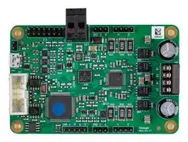
TMCM-1316 STEPROCKER_SERVO
Stepper Motor Controller, StepRocker™, Single Axis, 2 Phase, Bipolar, 5.7 A, 10 to 30 Vdc
⚠️ Reference pricing provided. In case of supply shortages, we will connect you with our trusted procurement partners to ensure your project's continuity.
- Manufacturer: TRINAMIC / ANALOG DEVICES
- Product type: Stepper Motor Drives
- Supply Voltage Min:10VDC; Supply Voltage Max:30VDC; No. of Phases:Two Phase; Power Rating:-; Output Voltage Max:-; Output Current:5.7A; Product ; Available until stocks are exhausted
- SVHC: No SVHC (21-Jan-2025)
- No. of Phases: Two Phase
- Product Range: TMCM StepRocker
- Output Current Max: 5.7A
- Supply Voltage Max: 30VDC
- Supply Voltage Min: 10VDC
- Control / Drive Type: 1-Axis Controller / Driver Module
| Delivery and price | |
|---|---|
| Units per pack | 1 |
| Price | 260.16 € |
| Current stock | 25+ |
| Lead time | 30 days |
Datasheet

**MODULE**

**Module for Stepper**

## TMCM-1316 Hardware Manual

Hardware Version V1.20 | Document Revision V1.21 • 2019-APR-15

**The TMCM-1316 StepRocker™Servo is a single axis motor controller/driver board for 2-phase bipolar stepper motors. It features the TRINAMIC controller/driver chain consisting of TMC4361 and TMC5160 in combination with an ARM Cortex-M4™(MK20DX128VLK7) processor. The Module is intended to be a fully functional development platform.**

## Features

- Single axis controller/driver for 2- phase bipolar stepper motor

- S-shaped ramps + SixPoint™ ramps + linear ramps

- Closed-loop operation with external encoder

- +10. . . 30V DC supply voltage

- Up to 5.7A RMS motor current

- RS485 & USB interface

- Multi-purpose inputs and outputs

## Applications

- Laboratory Automation

   - Factory Automation

- Manufacturing

   - Test & Measurement

- Robotics • Technology evaluation

- First experiences with stepper motors

- Hobby applications

Simplified Block Diagram

**==> picture [380 x 178] intentionally omitted <==**

**----- Start of picture text -----**<br>
Step/Dir<br>Inputs<br>REFL/REFR/<br>HOME<br>TMCL™<br>Memory<br>SPI<br>Stepper<br>RS485GPIOUSB MicrocontrollerCortex M4™ARM SPI Energy EfficientContStepperDriMotorTMC262 rollerver Energy EfficientStepperDriverDriverMotorTMC262<br>(TMC4361) TMC5160<br>Motor<br>CAN<br>10...30V DC<br>TMCM-1316 ENCODER<br>A/B/N<br>POE<br>E<br>**----- End of picture text -----**<br>


> ©2019 TRINAMIC Motion Control GmbH & Co. KG, Hamburg, Germany Terms of delivery and rights to technical change reserved. Download newest version at: www.trinamic.com

Read entire documentation.

TMCM-1316 Hardware Manual • Hardware Version V1.20 | Document Revision V1.21 • 2019-APR-15

2 / 25

## **Contents**

|**1**|**Features**||**3**|
|---|---|---|---|
|**2**|**Order Codes**||**4**|
|**3**|**Mechanical and Electrical Interfacing**||**5**|
||3.1<br>Size of board . . . . . . . . . .|. . . . . . . . . . . . . . . . . . . . . . . . . . . . . . . . . . . . .|5|
|**4**|**Connectors**||**6**|
||4.1<br>Power Connector . . . . . . . .|. . . . . . . . . . . . . . . . . . . . . . . . . . . . . . . . . . . . .|8|
||4.2<br>I/O Connector (Microcontroller) . . . . . . . . . . . . . . . . . . . . . . . . . . . . . . . . . . . .||8|
||4.3<br>Motor Connector . . . . . . . .|. . . . . . . . . . . . . . . . . . . . . . . . . . . . . . . . . . . . .|9|
||4.4<br>STOP_L, STOP_R, HOME and START connector pin assignment . . . . . . . . . . . . . . . . . .||9|
||4.5<br>Step/Dir Input Connector Pin Assignment . . . . . . . . . . . . . . . . . . . . . . . . . . . . . .||10|
||4.6<br>Step/Dir Output Connector Pin|Assignment . . . . . . . . . . . . . . . . . . . . . . . . . . . . .|10|
||4.7<br>RS485 and CAN Connector . .|. . . . . . . . . . . . . . . . . . . . . . . . . . . . . . . . . . . . .|10|
||4.7.1 Upgrade the StepRocker Servo for CAN communication . . . . . . . . . . . . . . . . . . .||11|
||4.8<br>USB Connector . . . . . . . . .|. . . . . . . . . . . . . . . . . . . . . . . . . . . . . . . . . . . . .|11|
||4.9<br>Microcontroller Programming Interface<br>. . . . . . . . . . . . . . . . . . . . . . . . . . . . . . .||12|
|**5**|**Jumper Settings**||**13**|
|**6**|**LEDs**||**14**|
|**7**|**Communication**||**15**|
||7.1<br>RS485<br>. . . . . . . . . . . . . .|. . . . . . . . . . . . . . . . . . . . . . . . . . . . . . . . . . . . .|15|
||7.2<br>USB . . . . . . . . . . . . . . . .|. . . . . . . . . . . . . . . . . . . . . . . . . . . . . . . . . . . . .|16|
||7.3<br>CAN (Retro-ft Option) . . . . .|. . . . . . . . . . . . . . . . . . . . . . . . . . . . . . . . . . . . .|16|
|**8**|**Functional Description**||**18**|
|**9**|**Operational Ratings and Characteristics**||**19**|
|**10 **|**Abbreviations used in this Manual**||**20**|
|**11 **|**Figures Index**||**21**|
|**12 **|**Tables Index**||**22**|
|**13 **|**Supplemental Directives**||**23**|
||13.1 Producer Information . . . . .|. . . . . . . . . . . . . . . . . . . . . . . . . . . . . . . . . . . . .|23|
||13.2 Copyright<br>. . . . . . . . . . . .|. . . . . . . . . . . . . . . . . . . . . . . . . . . . . . . . . . . . .|23|
||13.3 Trademark Designations and Symbols . . . . . . . . . . . . . . . . . . . . . . . . . . . . . . . .||23|
||13.4 Target User . . . . . . . . . . .|. . . . . . . . . . . . . . . . . . . . . . . . . . . . . . . . . . . . .|23|
||13.5 Disclaimer: Life Support Systems . . . . . . . . . . . . . . . . . . . . . . . . . . . . . . . . . . .||23|
||13.6 Disclaimer: Intended Use . . .|. . . . . . . . . . . . . . . . . . . . . . . . . . . . . . . . . . . . .|23|
||13.7 Collateral Documents & Tools|. . . . . . . . . . . . . . . . . . . . . . . . . . . . . . . . . . . . .|24|
|**14 **|**Revision History**||**25**|
||14.1 Hardware Revision . . . . . . .|. . . . . . . . . . . . . . . . . . . . . . . . . . . . . . . . . . . . .|25|
||14.2 Document Revision<br>. . . . . .|. . . . . . . . . . . . . . . . . . . . . . . . . . . . . . . . . . . . .|25|


> ©2019 TRINAMIC Motion Control GmbH & Co. KG, Hamburg, Germany Terms of delivery and rights to technical change reserved. Download newest version at www.trinamic.com

TMCM-1316 Hardware Manual • Hardware Version V1.20 | Document Revision V1.21 • 2019-APR-15

3 / 25

## **1 Features**

The TMCM-1316 StepRocker™ Servo is a single axis motor controller/driver board for 2-phase bipolar stepper motors. It supports S-shaped ramps in addition to linear ramps and closed-loop operation together with an external encoder. The TMCM-1316 features the TRINAMIC controller/driver chain consisting of TMC4361 and TMC5160 in combination with an ARM Cortex-M4™ (MK20DX128VLK7) processor. The Module is intended to be a fully functional development platform.

## **Applications**

- Highly compact single axis stepper motor controller/driver board for 2-phase bipolar stepper motors

## **Electrical data**

- Supply voltage: +24V DC (+10. . . +30V DC)

- Motor current: up to 1.1A RMS, 3.4A RMS or 5.7A RMS (can be selected with jumpers)

## **Mechanical data**

- Board size: 85mm x 55mm, height 15mm max. without mating connectors

- 4 mounting holes for M3 screws

## **Interfaces**

- RS485 host interface

- USB 2.0 host interface (USB micro-B connector)

- Step/Dir input (TTL level)

- Step/Dir output (+5V TTL level) for synchronisation (master-slave axes)

- 3 multi-purpose inputs (can be used for ABN-encoder)

- STOP_L, STOP_R and HOME inputs

- START input for synchronized motion with several axes

- 6 multi-purpose I/Os

- 2 open-drain outputs

- 1 analog input (0. . . 10V)

- µC programming interface SWD (single wire debug / pads on PCB)

- Retro-fit option: CAN 2.0B communication interface

## **Features**

- TMC4361 stepper motor controller IC for on-the-fly alteration of many motion specific parameters, linear, SixPoint™, and S-shaped ramp and closed-loop support

- TMC5160 advanced stepper motor driver IC with stallGuard2™ and coolStep™ features. Using the spreadCycle™ chopper the µ step current sine wave is well formed with smooth zero crossing. stealthChop2™can be selected for quiet operation and smooth movements.

- Up to 256 microsteps per fullstep trough mircoPlyer™technology

- EEPROM

## **Software**

- TMCL™ remote (direct mode) and standalone operation (memory for up to 1024 TMCL™ commands)

- Fully supported by TMCL-IDE (PC based integrated development environment)

> ©2019 TRINAMIC Motion Control GmbH & Co. KG, Hamburg, Germany Terms of delivery and rights to technical change reserved. Download newest version at www.trinamic.com

TMCM-1316 Hardware Manual • Hardware Version V1.20 | Document Revision V1.21 • 2019-APR-15

4 / 25

## **2 Order Codes**

The standard version of the StepRocker™ Servo has RS485 and USB interfaces (CAN transceiver **not** assembled).

The module is pre-programmed with TRINAMICs TMCL™firmware with all available features.

|TMCM-1316 Order Code|TMCM-1316 Order Code|TMCM-1316 Order Code|
|---|---|---|
|Order Code|Description|Size (LxWxH)|
|TMCM-1316 StepRocker_Servo|1-axis bipolar stepper motor controller/-<br>driver module with RS485 and USB, 5.7A<br>RMS, +24V|85mm x 55mm x 15mm|


_Table 1: TMCM-1316 Order Code_

> ©2019 TRINAMIC Motion Control GmbH & Co. KG, Hamburg, Germany Terms of delivery and rights to technical change reserved. Download newest version at www.trinamic.com

TMCM-1316 Hardware Manual • Hardware Version V1.20 | Document Revision V1.21 • 2019-APR-15

5 / 25

## **3 Mechanical and Electrical Interfacing**

## **3.1 Size of board**

The board with the controller/driver electronics has an overall size of 85mm x 55mm x 15mm without mating connectors. It offers four mounting holes for M3 screws (3.2mm diameter). All four mounting holes are connected to the ground plane (signal and supply ground) of the module.

**==> picture [339 x 231] intentionally omitted <==**

**----- Start of picture text -----**<br>
4<br>4<br>Ø 3.2<br>55<br>4 x M3<br>screws<br>4<br>85<br>**----- End of picture text -----**<br>


_Figure 1: Board Dimensions and Positions of Mounting Holes (all Values in mm)_

> ©2019 TRINAMIC Motion Control GmbH & Co. KG, Hamburg, Germany Terms of delivery and rights to technical change reserved. Download newest version at www.trinamic.com

TMCM-1316 Hardware Manual • Hardware Version V1.20 | Document Revision V1.21 • 2019-APR-15

6 / 25

## **4 Connectors**

The TMCM-1316 StepRocker Servo has nine connectors altogehter. There are two screw connectors for power and motor and two interface connectors (micro-USB and RS485). Furthermore, the StepRocker Servo has one connector for reference and home switches and synchronisation signal (START), one step/direction input connector (TTL level) and one output connector and the GPIO connector, which can be used e.g. for connecting an ABN-encoder.

_**NOTICE**_ **Start with power supply OFF and do not connect or disconnect motor during operation!** Motor cable and motor inductivity might lead to voltage spikes when the motor is (dis)connected while energized. These voltage spikes might exceed voltage limits of the driver MOSFETs and might permanently damage them. Therefore, always switch off / disconnect power supply or at least disable driver stage before connecting / disconnecting motor.

**==> picture [452 x 420] intentionally omitted <==**

**----- Start of picture text -----**<br>
Power<br>Step/Dir<br>In<br>GPIO<br>=e 1<br>1 . | 1 Fae e 1 nos 0 | en<br>+5V Output .MET(easAfi inhokia) eee tae 0302 weanwd i ifl aM220 Ay aeSal| |=i] eeS}_—--- eAf iyaah oe‘3<br>USB ayo» Ss ‘aigea wesaay om<3 =f a)olaS aiareean 8)==  Biseeae Boon tbsis  nSean ORGSeyslese== t Sedee<br>a= = Lg bios 55° Se CLE ES a eegeu “<br>9 WS ee Sarl wis a “9 Som om = Rake = > igs e 1<br>gy TOS See pe EER Sie ee. S|<br>RS485 Eehe pee [Il][ aaag] payasoU0= [cde] a mSaos wa he:SI8 SG: epeesseeesego3:ECana =$=Fes== i)eaeSSM7g Pefmh &eS. ee—, |. =|| IC|of ::| Motor<br>|b (ala ms i eeak wd “a DINGO HTH Nig 2 |! | ri]<br>aeS entittem ep eRe Balen a<br>> Je omy 2 EEECCEREEEEERREAEEE ee oaattha. 5 Ciiss eet =<br>(CAN | apes: eoga @5)../8 ate 58 ee OWS.<br>optional) lelanawen at= 3ES init aey caer) OIAGL asz0 nsw as -= 7f BOsARN<br>C) 1 “= = aome le EE ee 4<br>nae ReGenkfe< awe(oom cangqWS= HEEGIEHEGGTTTSTGG) 7©Ez terem)0  flaW200wenn7 oa)e205 rdwen| teatek [=| PLleap o|ic i~‘aanis °<br>e.- = hap GND L RH S Ary GNDS 0 " 12 TRINAMIC «= @<br>1 1<br>STOP_L, Step/Dir<br>STOP_R, Out<br>HOME,<br>START<br>Figure 2: TMCM-1316 StepRocker Servo Connectors<br>Connector Types and Mating Connectors<br>Connector Connector type on-board Mating connector type<br>Power RIA 220-02, 2 pin, 5.08mm pitch, RIA 249-02, screw type terminal block,<br>shrouded header pluggable, centerline 5.08mm pitch<br>Motor RIA 183-04, 4 pin, 3.5mm pitch, RIA 169-04, screw type terminal block,<br>schrouded header pluggable, centerline 3.5mm pitch<br>USB USB-micro-B female connector USB-micro male connector<br>**----- End of picture text -----**<br>


> ©2019 TRINAMIC Motion Control GmbH & Co. KG, Hamburg, Germany Terms of delivery and rights to technical change reserved. Download newest version at www.trinamic.com

TMCM-1316 Hardware Manual • Hardware Version V1.20 | Document Revision V1.21 • 2019-APR-15

7 / 25

|Connector|Connector type on-board|Mating connector type|
|---|---|---|
|RS485/CAN|Low profle box header without lock-<br>ing bar, type 8380, 10 pin, DIN 41651,<br>2.54mm pitch|Low profle IDC socket connector, 10<br>pin, DIN 41651, 2.54mm pitch|
|GPIO|Header, double row, 14 pin, 2.54mm<br>pitch|Female connector with 2.54mm pitch|
|STOP_L,<br>STOP_R,<br>HOME, START|Header, 5 pin, 2.54mm pitch|Female connector with 2.54mm pitch|
|Step/Dir In|Header, 3 pin, 2.54mm pitch|Female connector with 2.54mm pitch|
|Step/Dir Out|Header, 3 pin, 2.54mm pitch|Female connector with 2.54mm pitch|
|+5V output|Header, 2 pin, 2.54mm pitch|Female connector with 2.54mm pitch|


_Table 2: Connector Types and Mating Connectors of the TMCM-1316 StepRocker Servo_

©2019 TRINAMIC Motion Control GmbH & Co. KG, Hamburg, Germany Terms of delivery and rights to technical change reserved. Download newest version at www.trinamic.com

TMCM-1316 Hardware Manual • Hardware Version V1.20 | Document Revision V1.21 • 2019-APR-15

8 / 25

## **4.1 Power Connector**

|Power Supply Connector Pin Assigment|Power Supply Connector Pin Assigment|Power Supply Connector Pin Assigment|Power Supply Connector Pin Assigment|
|---|---|---|---|
|Pin|Label|Direction|Description|
|1|GND|Power (GND)|Common system supply and signal ground|
|2|12. . . 30V|Power (input)|Power supply voltage|


_Table 3: Power Supply Connector Pin Assignment_

|**_NOTICE_**|**Do not connect or disconnect motor during operation!** Motor cable and mo-<br>|
|---|---|
|tor inductivity might lead to voltage spikes when the motor is (dis)connected<br>while energized. These voltage spikes might exceed voltage limits of the driver<br>MOSFETs and might permanently damage them. Therefore, always switch of<br>/ disconnect power supply or at least disable driver stage before connecting /<br>disconnecting motor.||
|||
|**_NOTICE_**|**Take care of polarity, wrong polarity can destroy the board!**|


## **4.2 I/O Connector (Microcontroller)**

The TMCM-1316 offers an on-board ARM Cortex-M4™ microcontroller with +3V3 powered IOs and +5V tolerant inputs. In order to be compatible with previous generations of the module, +5V output levelshifters/buffers have been integrated on-board. This way, all general purpose IO pins configured as outputs will deliver +5V TTL signals.

|GPIO Connector Pin Assignment|GPIO Connector Pin Assignment|GPIO Connector Pin Assignment|GPIO Connector Pin Assignment|
|---|---|---|---|
|Pin|Label|Direction|Description|
|1|GND|Power (GND)|Supply and signal ground|
|2|GND|Power (GND)|Supply and signal ground|
|3|PWMD_0|in/out|General purpose I/O (+5V compatible,<br>default: input)|
|4|PWMU_0|in/out|General purpose I/O (+5V compatible,<br>default: output)|
|5|PWMD_1|in/out|General purpose I/O (+5V compatible,<br>default: input)|
|6|PWMU_1|in/out|General purpose I/O (+5V compatible,<br>default: output)|
|7|PWMD_2|in/out|General purpose I/O (+5V compatible,<br>default: input)|
|8|PWMU_2|in/out|General purpose I/O (+5V compatible,<br>default: output)|
|9|AIN_0|in|Analog input<br>Input voltage range: 0. . . +10V<br>Resolution: 12bit (0. . . 4095)|


©2019 TRINAMIC Motion Control GmbH & Co. KG, Hamburg, Germany Terms of delivery and rights to technical change reserved. Download newest version at www.trinamic.com

TMCM-1316 Hardware Manual • Hardware Version V1.20 | Document Revision V1.21 • 2019-APR-15

9 / 25

|Pin|Label|Direction|Description|
|---|---|---|---|
|10|PHASE_A|in|Encoder input channel A (+5V compat-<br>ible, internal pull-up to +5V)|
|11|OpenDrain_1|out|Open-drain output (max. 100mA)|
|12|PHASE_B|in|Encoder input channel B (+5V compat-<br>ible, internal pull-up to +5V)|
|13|OpenDrain_2|out|Open-drain output (max. 100mA)|
|14|PHASE_Z|in|Encoder input zero channel (+5V com-<br>patible, internal pull-up to +5V)|


_Table 4: I/O Connector Pin Assignment_

## **4.3 Motor Connector**

The motor has to be connected to the motor connector, one phase (phase A) between A1 and A2 and the second phase (phase B) between B1 and B2.

|Motor Connector Pin Assignment|Motor Connector Pin Assignment|Motor Connector Pin Assignment|Motor Connector Pin Assignment|
|---|---|---|---|
|Pin|Label|Direction|Description|
|1|B1|out|Pin 1 of motor coil B|
|2|B2|out|Pin 2 of motor coil B|
|3|A1|out|Pin 1 of motor coil A|
|4|A2|out|Pin 2 of motor coil A|


_Table 5: Motor Connector Pin Assignment_

_**NOTICE**_ **Do not connect or disconnect motor during operation!** Motor cable and motor inductivity might lead to voltage spikes when the motor is (dis)connected while energized. These voltage spikes might exceed voltage limits of the driver MOSFETs and might permanently damage them. Therefore, always switch off / disconnect power supply or at least disable driver stage before connecting / disconnecting motor.

## **4.4 STOP_L, STOP_R, HOME and START connector pin assignment**

|STOP_L, STOP_R, HOME and START connector pin assignment|STOP_L, STOP_R, HOME and START connector pin assignment|STOP_L, STOP_R, HOME and START connector pin assignment|STOP_L, STOP_R, HOME and START connector pin assignment|
|---|---|---|---|
|Pin|Label|Direction|Description|
|1|GND|Power (GND)|Signal and system ground|
|2|STOP_L|in|Input for left stop/limit switch|
|3|STOP_R|in|Input for right stop/limit switch|
|4|HOME|in|Input for home/reference switch|


©2019 TRINAMIC Motion Control GmbH & Co. KG, Hamburg, Germany Terms of delivery and rights to technical change reserved. Download newest version at www.trinamic.com

TMCM-1316 Hardware Manual • Hardware Version V1.20 | Document Revision V1.21 • 2019-APR-15

10 / 25

|Pin|Label|Direction|Description|
|---|---|---|---|
|5|START|in|Input for start signal (master / slave synchronisa-<br>tion)|


_Table 6: STOP_L, STOP_R, HOME and START Connector Pin Assignment_

## **4.5 Step/Dir Input Connector Pin Assignment**

|Step/Dir Input connector pin assignment|Step/Dir Input connector pin assignment|Step/Dir Input connector pin assignment|Step/Dir Input connector pin assignment|
|---|---|---|---|
|Pin|Label|Direction|Description|
|1|GND|Power (GND)|Signal and system ground|
|2|STEP_IN|in|Input for step pulse signal|
|3|DIR_IN|in|Input for direction signal|


_Table 7: Step/Dir Input Connector Pin Assignment_

## **4.6 Step/Dir Output Connector Pin Assignment**

|Step/Dir Output connector pin assignment|Step/Dir Output connector pin assignment|Step/Dir Output connector pin assignment|Step/Dir Output connector pin assignment|
|---|---|---|---|
|Pin|Label|Direction|Description|
|1|GND|Power (GND)|Signal and system ground|
|2|STEP_OUT|in|Output for step pulse signal|
|3|DIR_OUT|in|Output for direction signal|


_Table 8: Step/Dir Output Connector Pin Assignment_

## **4.7 RS485 and CAN Connector**

The standard TMCM-1316 StepRocker Servo offers the RS485 interface, only.

|RS485/CAN Connector Pin Assignment|RS485/CAN Connector Pin Assignment|RS485/CAN Connector Pin Assignment|RS485/CAN Connector Pin Assignment|
|---|---|---|---|
|Pin|Label|Direction|Description|
|1||||
|2||||
|3|CAN_L|bi-directional|diferential CAN bus signal (inverting) - retro-ft<br>option|
|4|CAN_H|bi-directional|diferential CAN bus signal (non-inverting) - retro-<br>ft option|
|5|GND|Power (GND)|Signal and system ground|
|6|RS485+|bi-directional|diferential RS485 bus signal (non-inverting)|
|7|RS485-|bi-directional|diferential RS485 bus signal (inverting)|


- ©2019 TRINAMIC Motion Control GmbH & Co. KG, Hamburg, Germany Terms of delivery and rights to technical change reserved. Download newest version at www.trinamic.com

TMCM-1316 Hardware Manual • Hardware Version V1.20 | Document Revision V1.21 • 2019-APR-15

11 / 25

|Pin|Label|Direction|Description|
|---|---|---|---|
|8||||
|9||||
|10||||


_Table 9: RS485/CAN Connector Pin Assignment_

## **4.7.1 Upgrade the StepRocker Servo for CAN communication**

The table above shows the pin configuration for CAN, too. Before starting with CAN it is necessary to solder a TJA1050T CAN transceiver with housing SOIC8 and a 0.1µ capacitor with housing 0603 on the TMCM-1316 StepRocker Servo. Afterwards, the StepRocker Servo is ready for using the CAN interface.

**==> picture [246 x 44] intentionally omitted <==**

**----- Start of picture text -----**<br>
CAN transceiver<br>RAR<br>TJA1050T<br>0.1uF capacitor<br>Housing: SOIC8<br>"= ee 8 GD<br>Housing: 0603<br>**----- End of picture text -----**<br>


Because of the pin assignment CAN and RS485 can be used at the same time.

Please note: it is not necessary to remove the RS485 transceiver.

## **4.8 USB Connector**

A USB interface is available via a micro-USB connector. This module supports USB 2.0 Full-Speed (12Mbit/s) connections.

|USB Connector Pin Assignment|USB Connector Pin Assignment|USB Connector Pin Assignment|USB Connector Pin Assignment|
|---|---|---|---|
|Pin|Label|Direction|Description|
|1|VBUS|Power (+5V input)|+5V supply from the host|
|2|D-|bi-directional|USB Data-|
|3|D+|bi-directional|USB Data+|
|4|ID||Connected to signal and system ground|
|5|GND|Power (GND)|Signal and system ground|


_Table 10: USB Connector Pin Assignment_

> ©2019 TRINAMIC Motion Control GmbH & Co. KG, Hamburg, Germany Terms of delivery and rights to technical change reserved. Download newest version at www.trinamic.com

TMCM-1316 Hardware Manual • Hardware Version V1.20 | Document Revision V1.21 • 2019-APR-15

12 / 25

## **4.9 Microcontroller Programming Interface**

The programming pads for the microcontroller are located on the bottom side of the module. They are connected directly to the related processor pins - resp. GND or on-board generated +3V3 supply. These pins are used for programming of the bootloader and firmware during production + testing of the module.

|Programming Pads|Programming Pads|Programming Pads|
|---|---|---|
|Pin|Label|Description|
|1|GND|Module and signal ground|
|2|+3V3|+3V3 DC supply - generated on-board|
|3|nRST|Hardware reset input|
|4|SWDIO|Serial wire data I/O|
|5|SWDCLK|Serial wire clock|


_Table 11: Programming Pads on Bottom of the PCB_

> ©2019 TRINAMIC Motion Control GmbH & Co. KG, Hamburg, Germany Terms of delivery and rights to technical change reserved. Download newest version at www.trinamic.com

TMCM-1316 Hardware Manual • Hardware Version V1.20 | Document Revision V1.21 • 2019-APR-15

13 / 25

## **5 Jumper Settings**

The TMCM-1316 StepRocker Servo offers a number of jumpers for selection of different settings in hardware.

_Figure 3: Jumper Settings of the TMCM-1316 StepRocker Servo_

|Jumpers of the TMCM-1316 StepRocker Servo|Jumpers of the TMCM-1316 StepRocker Servo|Jumpers of the TMCM-1316 StepRocker Servo|
|---|---|---|
|Jumper|Label|Description|
|Select motor current|Jumper removed|Jumper removed: motor current up to 1.1A RMS|
||Jumper pin 1-2|1 Jumper populated (pin 1-2): motor current up to<br>3.4A RMS|
||Jumper pin 1-2_and_3-4|2 Jumper populated (pin 1-2 and pin 3-4): motor<br>current up to 5.7A RMS|


_Table 12: Jumpers of the TMCM-1316 StepRocker Servo_

> ©2019 TRINAMIC Motion Control GmbH & Co. KG, Hamburg, Germany Terms of delivery and rights to technical change reserved. Download newest version at www.trinamic.com

TMCM-1316 Hardware Manual • Hardware Version V1.20 | Document Revision V1.21 • 2019-APR-15

14 / 25

## **6 LEDs**

|LED Description|LED Description|LED Description|
|---|---|---|
|Status|Label|Description|
|Power on|+5V|This orange LED lights up upon the power<br>supply is available|
|LED1 without pre-defined functionality|LED1|This yellow LED can be used customer spe-<br>cific. This LED is connected to PTA5 (pin 31)<br>of the MK20DX128VLK7 microcontroller.|
|LED2 without pre-defined functionality|LED2|This yellow LED can be used customer spe-<br>cific. This LED is connected to PTE5 (pin 6)<br>of the MK20DX128VLK7 microcontroller.|
|TMC5160 diagnosis output 0|DIAG_0|This green LED lights up if the DIAG 0 output<br>of the TMC5160 is pulled low.|
|TMC5160 diagnosis output 1|DIAG_1|This green LED lights up if the DIAG 1 output<br>of the TMC5160 is pulled low.|


_Table 13: LED Description_

_Figure 4: TMCM-1316 LEDs_

> ©2019 TRINAMIC Motion Control GmbH & Co. KG, Hamburg, Germany Terms of delivery and rights to technical change reserved. Download newest version at www.trinamic.com

TMCM-1316 Hardware Manual • Hardware Version V1.20 | Document Revision V1.21 • 2019-APR-15

15 / 25

## **7 Communication**

## **7.1 RS485**

For remote control and communication with a host system the TMCM-1316 provides a two wire RS485 bus interface. For proper operation the following items should be taken into account when setting up an RS485 network:

1. _BUS STRUCTURE:_

   - The network topology should follow a bus structure as closely as possible. That is, the connection between each node and the bus itself should be as short as possible. Basically, it should be short compared to the length of the bus.

**==> picture [416 x 129] intentionally omitted <==**

**----- Start of picture text -----**<br>
Host<br>Slave Slave Slave<br>c:><br>node node node<br>1 n - 1 n<br>}<br>termination termination<br>resistor resistor<br>(120 Ohm) (120 Ohm)<br>RS485 keep distance as<br>short as possible<br>**----- End of picture text -----**<br>


_Figure 5: RS485 Bus Structure with Termination Resistors_

2. _BUS TERMINATION:_

   - Especially for longer busses and/or multiple nodes connected to the bus and/or high communication speeds, the bus should be properly terminated at both ends. The TMCM-1316 does not intergate any termination resistor. Therefore, 120 Ohm termination resistors at both ends of the bus have to be added externally.

3. _NUMBER OF NODES:_

   - The RS485 electrical interface stadard (EIA-485) allows up to 32 nodes to be connected to a single bus. The bus transceiver used on the TMCM-1316 units (SN65HVD3082ED) has just 1/8th of the standard bus load and allows a maximum of 256 units to be connected to a single RS485 bus.

4. _NO FLOATING BUS LINES:_

   - Avoid floating bus lines while neither the host/master nor one of the slaves along the bus line is transmitting data (all bus nodes switched to receive mode). Floating bus lines may lead to communication errors. In order to ensure valid signals on the bus it is recommended to use a resistor network connecting both bus lines to GND resp. +5V. In contrast to the termination resistors this network is normally required just once per bus. Certain RS485 interface converters available for PCs already include these additional resistors (e.g. USB-2-485).

> ©2019 TRINAMIC Motion Control GmbH & Co. KG, Hamburg, Germany Terms of delivery and rights to technical change reserved. Download newest version at www.trinamic.com

TMCM-1316 Hardware Manual • Hardware Version V1.20 | Document Revision V1.21 • 2019-APR-15

16 / 25

**==> picture [283 x 138] intentionally omitted <==**

**----- Start of picture text -----**<br>
Slave Slave<br>node node +5V<br>n  - 1 n<br>pull-up (680R)<br>RS485+ / RS485A termination<br>resistor<br>RS485- / RS485B (120 Ohm)<br>pull-down (680R)<br>GND<br>**----- End of picture text -----**<br>


_Figure 6: RS485 Bus Lines with Resistor Network_

## **7.2 USB**

For remote control and communication with a host system the TMCM-1316 StepRocker Servo provides a USB 2.0 full-speed (12Mbit/s) interface (mini-USB connector). As soon as a USB-Host is connected the module will accept commands via USB. The TMCM-1316 supports USB self powered operation (External power supplied via the power supply connector) and USB bus powered operation, also (no external power is supplied via the power supply connector). During USB bus powered operation, only the core digital circuit parts will be operational. That is, the microcontroller itself and also the EEPROM. Of course, any motor movement will not be possible in this mode. This mode has been implemented in order to enable configuration / parameter setting / read-out, firmware updates etc. by just connecting a USB cable between the module and a host PC. No other connection / additional power supply is required.

## **7.3 CAN (Retro-fit Option)**

For remote control and communciation with a host system the TMCM-1316 StepRocker Servo can be equipped with a CAN bus interface. Please note, that it is necessary to add CAN transceiver and filter capacitor first for the standard TMCM-1316 StepRocker Servo version (see 4.7.1).

For proper operation the following items should be taken into account when setting up a CAN network:

## 1. _BUS STRUCTURE:_

The network topology should follow a bus structure as closely as possible. That is, the connection between each node and the bus itself should be as short as possible. Basically, it should be short compared to the length of the bus.

**==> picture [416 x 129] intentionally omitted <==**

**----- Start of picture text -----**<br>
Host<br>Slave Slave Slave<br>c:><br>node node node<br>1 n - 1 n<br>}<br>termination termination<br>resistor resistor<br>(120 Ohm) (120 Ohm)<br>CAN keep distance as<br>short as possible<br>**----- End of picture text -----**<br>


_Figure 7: CAN Bus Structure with Termination Resistors_

> ©2019 TRINAMIC Motion Control GmbH & Co. KG, Hamburg, Germany Terms of delivery and rights to technical change reserved. Download newest version at www.trinamic.com

TMCM-1316 Hardware Manual • Hardware Version V1.20 | Document Revision V1.21 • 2019-APR-15

17 / 25

## 2. _BUS TERMINATION:_

Especially for longer busses and/or multiple nodes connected to the bus and/or high communication speeds, the bus should be properly terminated at both ends. The TMCM-1316 does not integrate any termination resistor. Therefore, 120 Ohm termination resistors at both ends of the bus have to be added externally.

> ©2019 TRINAMIC Motion Control GmbH & Co. KG, Hamburg, Germany Terms of delivery and rights to technical change reserved. Download newest version at www.trinamic.com

TMCM-1316 Hardware Manual • Hardware Version V1.20 | Document Revision V1.21 • 2019-APR-15

18 / 25

## **8 Functional Description**

The TMCM-1316 is a highly integrated single axis controller/driver module for stepper motors. The TMCM-1316 can be controlled via RS485 or USB serial interfaces (CAN retro-fit option).

The TMCM-1316 comes with the PC based software development environment TMCL-IDE for the Trinamic Motion Control Language (TMCL™). Using predefined TMCL™ high level commands like _move to position_ a rapid and fast development of motion control applications is guaranteed. Whereas the boot loader is installed during production and testing at TRINAMIC and remains usually untouched throughout the whole lifetime, the firmware ca be updated by the user.

Communication traffic is kept low since all time critical operations, e.g. ramp calculation, are performed on-board. Full remote control of the device with feedback is possible. The firmware of the module can be updated via any of the serial interfaces.

## **The TMCM-1316 module contains the following main components:**

- Microcontroller (ARM Cortex-M4™, MK20DX128VLK7), responsible for overall control and communication

- TMC4361 highly integrated advanced stepper motor controller. Supports linear and S-shaped ramps. Together with an external encoder closed-loop operation is supported.

- TMC5160 advanced stepper motor driver IC with stallGuard2™ and coolStep™ with MOSFET driver stage (8x NMOSFETs for bipolar stepper motor)

- RS485 and USB transceivers

- On-board voltage regulators (+5V and +3V3) required for supply of all on-board digital circuits

**==> picture [436 x 215] intentionally omitted <==**

**----- Start of picture text -----**<br>
Step/Dir<br>Inputs<br>REFL/REFR/<br>HOME<br>TMCL™<br>Memory<br>SPI<br>Stepper<br>RS485GPIOUSB MicrocontrollerCortex M4™ARM SPI Energy EfficientContStepperDriMotorTMC262 rollerver Energy EfficientStepperDriverDriverMotorTMC262<br>(TMC4361) TMC5160<br>Motor<br>CAN<br>10...30V DC<br>TMCM-1316 ENCODER<br>A/B/N<br>E<br>**----- End of picture text -----**<br>


_Figure 8: TMCM-1316 Block Diagram_

> ©2019 TRINAMIC Motion Control GmbH & Co. KG, Hamburg, Germany Terms of delivery and rights to technical change reserved. Download newest version at www.trinamic.com

TMCM-1316 Hardware Manual • Hardware Version V1.20 | Document Revision V1.21 • 2019-APR-15

19 / 25

## **9 Operational Ratings and Characteristics**

_**NOTICE**_ **Never Exceed the absolute maximum ratings!** Keep the power supply voltage below the upper limit of +30V! Otherwise the board electronics will seriously be damaged! Especially, when the selected operating voltage is near the upper limit a regulated power supply is highly recommended.

|General Operational Ratings|General Operational Ratings|General Operational Ratings|General Operational Ratings|General Operational Ratings|General Operational Ratings|
|---|---|---|---|---|---|
|Symbol|Parameter|Min|Typ|Max|Unit|
|VPower|Power supply voltage|10|24|30|V|
|VUSB|Power supply via USB connector||5||V|
|IUSB|Current withdrawn from USB supply when USB<br>bus powered (no other supply connected)||80||mA|
|ICOIL|Motor coil current for sine wave **peak (chopper**<br>**regulated, adjustable via software)**|0||1.6 or 4.8 or 8.1|A|
|IMC|Continuous motor current (**RMS)**|0||1.1 or 3.4 or 5.7|A|
|TENV|Environmental temperature at rated current (no<br>forced cooling reaquired)|-25||50|°C|


_Table 14: General Operational Ratings of the Module_

|Operational Ratings of the RS485 Interface|Operational Ratings of the RS485 Interface|Operational Ratings of the RS485 Interface|Operational Ratings of the RS485 Interface|Operational Ratings of the RS485 Interface|Operational Ratings of the RS485 Interface|
|---|---|---|---|---|---|
|Symbol|Parameter|Min|Typ|Max|Unit|
|NRS485|Number of nodes connected to single RS485 network|||256||


_Table 15: Operational Ratings of the RS485 Interface_

> ©2019 TRINAMIC Motion Control GmbH & Co. KG, Hamburg, Germany Terms of delivery and rights to technical change reserved. Download newest version at www.trinamic.com

TMCM-1316 Hardware Manual • Hardware Version V1.20 | Document Revision V1.21 • 2019-APR-15

20 / 25

## **10 Abbreviations used in this Manual**

|Abbreviation|Description|
|---|---|
|IDE|Integrated Development Environment|
|LED|Light Emmitting Diode|
|RMS|Root Mean Square value|
|TMCL|TRINAMIC Motion Control Language|


_Table 16: Abbreviations used in this Manual_

> ©2019 TRINAMIC Motion Control GmbH & Co. KG, Hamburg, Germany Terms of delivery and rights to technical change reserved. Download newest version at www.trinamic.com

TMCM-1316 Hardware Manual • Hardware Version V1.20 | Document Revision V1.21 • 2019-APR-15

21 / 25

## **11 Figures Index**

- 1 Board Dimensions and Positions of 5 RS485 Bus Structure with Termination Mounting Holes (all Values in mm) . . . 5 Resistors . . . . . . . . . . . . . . . . . . . 15

- 2 TMCM-1316 StepRocker Servo Connectors 6 6 RS485 Bus Lines with Resistor Network . 16 3 Jumper Settings of the TMCM-1316 7 CAN Bus Structure with Termination StepRocker Servo . . . . . . . . . . . . . . 13 Resistors . . . . . . . . . . . . . . . . . . . 16

- 4 TMCM-1316 LEDs . . . . . . . . . . . . . . 14 8 TMCM-1316 Block Diagram . . . . . . . . 18

> ©2019 TRINAMIC Motion Control GmbH & Co. KG, Hamburg, Germany Terms of delivery and rights to technical change reserved. Download newest version at www.trinamic.com

TMCM-1316 Hardware Manual • Hardware Version V1.20 | Document Revision V1.21 • 2019-APR-15

22 / 25

## **12 Tables Index**

|1|TMCM-1316 Order Code . . . . . .|. . .|4|10 USB Connector Pin Assignment|. . . .|11|
|---|---|---|---|---|---|---|
|2|Connector Types and Mating|||11 Programming Pads on Bottom of|the PCB|12|
||Connectors of the TMCM-1316|||12 Jumpers of the TMCM-1316 StepRocker|||
||StepRocker Servo . . . . . . . . . .|. . .|7|Servo . . . . . . . . . . . . . . . .|. . . .|13|
|3|Power Supply Connector Pin Assignment||8|13 LED Description . . . . . . . . . .|. . . .|14|
|4|I/O Connector Pin Assignment . .|. . .|9|14 General Operational Ratings of the|||
|5|Motor Connector Pin Assignment|. . .|9|Module . . . . . . . . . . . . . . .|. . . .|19|
|6|STOP_L, STOP_R, HOME and START|||15 Operational Ratings of the RS485|||
||Connector Pin Assignment<br>. . . .|. . .|10|Interface . . . . . . . . . . . . . .|. . . .|19|
|7|Step/Dir Input Connector Pin Assignment||10|16 Abbreviations used in this Manual . . .||20|
|8|Step/Dir Output Connector Pin|||17 Hardware Revision . . . . . . . .|. . . .|25|
||Assignment<br>. . . . . . . . . . . . .|. . .|10|18 Document Revision . . . . . . . .|. . . .|25|
|9|RS485/CAN Connector Pin Assignment||11||||


> ©2019 TRINAMIC Motion Control GmbH & Co. KG, Hamburg, Germany Terms of delivery and rights to technical change reserved. Download newest version at www.trinamic.com

TMCM-1316 Hardware Manual • Hardware Version V1.20 | Document Revision V1.21 • 2019-APR-15

23 / 25

## **13 Supplemental Directives**

## **13.1 Producer Information**

## **13.2 Copyright**

TRINAMIC owns the content of this user manual in its entirety, including but not limited to pictures, logos, trademarks, and resources. © Copyright 2019 TRINAMIC. All rights reserved. Electronically published by TRINAMIC, Germany.

Redistributions of source or derived format (for example, Portable Document Format or Hypertext Markup Language) must retain the above copyright notice, and the complete Datasheet User Manual documentation of this product including associated Application Notes; and a reference to other available product-related documentation.

## **13.3 Trademark Designations and Symbols**

Trademark designations and symbols used in this documentation indicate that a product or feature is owned and registered as trademark and/or patent either by TRINAMIC or by other manufacturers, whose products are used or referred to in combination with TRINAMIC’s products and TRINAMIC’s product documentation.

This Hardware Manual is a non-commercial publication that seeks to provide concise scientific and technical user information to the target user. Thus, trademark designations and symbols are only entered in the Short Spec of this document that introduces the product at a quick glance. The trademark designation /symbol is also entered when the product or feature name occurs for the first time in the document. All trademarks and brand names used are property of their respective owners.

## **13.4 Target User**

The documentation provided here, is for programmers and engineers only, who are equipped with the necessary skills and have been trained to work with this type of product.

The Target User knows how to responsibly make use of this product without causing harm to himself or others, and without causing damage to systems or devices, in which the user incorporates the product.

## **13.5 Disclaimer: Life Support Systems**

TRINAMIC Motion Control GmbH & Co. KG does not authorize or warrant any of its products for use in life support systems, without the specific written consent of TRINAMIC Motion Control GmbH & Co. KG.

Life support systems are equipment intended to support or sustain life, and whose failure to perform, when properly used in accordance with instructions provided, can be reasonably expected to result in personal injury or death.

Information given in this document is believed to be accurate and reliable. However, no responsibility is assumed for the consequences of its use nor for any infringement of patents or other rights of third parties which may result from its use. Specifications are subject to change without notice.

## **13.6 Disclaimer: Intended Use**

The data specified in this user manual is intended solely for the purpose of product description. No representations or warranties, either express or implied, of merchantability, fitness for a particular purpose

> ©2019 TRINAMIC Motion Control GmbH & Co. KG, Hamburg, Germany Terms of delivery and rights to technical change reserved. Download newest version at www.trinamic.com

TMCM-1316 Hardware Manual • Hardware Version V1.20 | Document Revision V1.21 • 2019-APR-15

24 / 25

or of any other nature are made hereunder with respect to information/specification or the products to which information refers and no guarantee with respect to compliance to the intended use is given.

In particular, this also applies to the stated possible applications or areas of applications of the product. TRINAMIC products are not designed for and must not be used in connection with any applications where the failure of such products would reasonably be expected to result in significant personal injury or death (safety-Critical Applications) without TRINAMIC’s specific written consent.

TRINAMIC products are not designed nor intended for use in military or aerospace applications or environments or in automotive applications unless specifically designated for such use by TRINAMIC. TRINAMIC conveys no patent, copyright, mask work right or other trade mark right to this product. TRINAMIC assumes no liability for any patent and/or other trade mark rights of a third party resulting from processing or handling of the product and/or any other use of the product.

## **13.7 Collateral Documents & Tools**

This product documentation is related and/or associated with additional tool kits, firmware and other items, as provided on the product page at: www.trinamic.com.

> ©2019 TRINAMIC Motion Control GmbH & Co. KG, Hamburg, Germany Terms of delivery and rights to technical change reserved. Download newest version at www.trinamic.com

TMCM-1316 Hardware Manual • Hardware Version V1.20 | Document Revision V1.21 • 2019-APR-15

25 / 25

## **14 Revision History**

## **14.1 Hardware Revision**

|Version|Date|Author|Description|
|---|---|---|---|
|V1.0|2018-JUN-21|MM|First version. Prototypes only.|
|V1.1|2018-JUL-17|MM|Several corrections.|
|V1.2|2019-MAR-21|MM|Corrections for using StealthChop™and StallGuard™/ CoolStep™.|


_Table 17: Hardware Revision_

## **14.2 Document Revision**

|Version|Date|Author|Description|
|---|---|---|---|
|1.00|2018-OCT-08|GE|First version.|
|1.10|2018-NOV-06|GE|Several corrections (incl. order code etc.).|
|1.20|2018-NOV-29|SK|Added SixPoint™ramp information.|
|1.21|2019-MAR-21|OK|New hardware revision number (V1.2).|


_Table 18: Document Revision_

> ©2019 TRINAMIC Motion Control GmbH & Co. KG, Hamburg, Germany Terms of delivery and rights to technical change reserved. Download newest version at www.trinamic.com
Updated at April 29, 2026
About Novapart
Novapart is a B2B electronic component broker specialising in stock shortages and cost reduction. We source hard-to-find parts and identify compliant alternatives across a catalogue of 410,000+ components from 500+ manufacturers.
Learn more →Stock Shortage Specialist
When a component is unavailable, discontinued or has an unacceptable lead time, we tap into our network of vetted European and Asian distributors to source what you need — without compromising on quality or traceability.
Request a quote →Compliant Alternatives
We identify pin-to-pin, electrically equivalent substitutes that meet the same certifications (RoHS, AEC-Q100, REACH) as your original specification — validated against datasheets, not just part numbers. Often at a lower cost.
BOM Analysis service →