
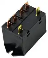


RL2B-D-D24
RELAY, DPDT, 24VDC, 25A, DIN-RAIL/PANEL
- Manufacturer: IDEC
- Product type: Power Relays
- Coil Voltage: 24VDC
- Product Range: RL Series
- Relay Mounting: DIN Rail, Panel
- Coil Resistance: 303ohm
- Contact Current: 25A
- Relay Terminals: Screw
- Contact Material: Silver Alloy
- Contact Voltage VAC: 250VAC
- Contact Voltage VDC: 30VDC
- Contact Configuration: DPDT
| Delivery and price | |
|---|---|
| Units per pack | 50 |
| Price | 11.62 € |
| Current stock | 10+ |
| Lead time | 30 days |
## Power Relays:

## RL Series

## **PRODUCT DESCRIPTION**

**==> picture [160 x 106] intentionally omitted <==**

**----- Start of picture text -----**<br>
Quick Connect<br>Flange Mount<br>Screw Terminal<br>DIN Rail Mount<br>**----- End of picture text -----**<br>


## **SPECIFICATIONS**

|||RL1|RL2|
|---|---|---|---|
|Number of poles||1 pole|2 poles|
|Contact Configuration||1X (SPST, double make)|2X (DPST, double make)|
|Contact material||Ag Alloy|Ag Alloy|
|Operating Time and Release Time||30ms max|30ms max|
|Degree of Protection||IP40|IP40|
|Dielectric strength|Between contact and coil|4,000V AC for 1 minute|4,000V AC for 1 minute|
||Between pole|2,000V AC for 1 minute|2,000V AC for 1 minute|
||Between contact sets|-|2,000V AC for 1 minute|
|Vibration Resistance|Operating extremes|Frequency 10 to 55 Hz,<br>Amplitude 0.75mm|Frequency 10 to 55 Hz,<br>Amplitude 0.75mm|
||Damage limits|Frequency 10 to 55 Hz,<br>Amplitude 0.75mm|Frequency 10 to 55 Hz,<br>Amplitude 0.75mm|
|Shock Resistance|Operating extremes|100 m/s² (10G)|100 m/s² (10G)|
||Damage limits|1,000 m/s² (100G)|1,000 m/s² (100G)|
|Electrical Life<br>(rated load).<br>Operation frequency<br>(1800 operations per hour)|AC resistive load|200,000 operations minimum|200,000 operations minimum|
||Inductive load|100,000 operations minimum|100,000 operations minimum|
|Mechanical Life (without load)||1,000,000 operations minimum|1,000,000 operations minimum|
|Operating Temperature||-25 to +55°C|-25 to +55°C|
|Operating Humidity||5 to 85% (without condensation)|5 to 85% (without<br>condensation)|
|Weight||Between 90 and 135 grams,<br>depending on model|Between 90 and 135 grams,<br>depending on model|


Designed with a 1- and 2-pole 3HP/277V AC rating in an economical and compact package, 30A RL power relays are the superior choice for HVAC panels, energy management and applications requiring higher voltage loads and inductive kickback. Choose from panel or DIN rail mounting.

Unlike the competition, when DIN rail mounted, RL relays don’t require a socket or adaptor. Quick Connect terminals allow faster installation on commercial applications, while screw terminations are ideal for industrial applications.

## **KEY FEATURES**

- 3HP at 277VAC, 1.5HP at 120VAC

- Single pole rated at 30A, double pole at 25A

- Double Make contacts

- Flange mount or DIN-rail mount with panel mount tabs

- #250 quick-connect or screw terminations

- AC or DC Coil Inputs

- Designed for Motor, Lighting, and Heater Loads

- Up to 7500 VA maximum switching power

- RoHS compliant

## **STANDARDS COMPLIANCE**

|Agencyratings|RL1|RL2|
|---|---|---|
|Standard current ratings|30 A, 277 Vac, General Use,<br>100,000 Cycles|25 A, 277 Vac, General Use,<br>100,000 cycles|
|HP ratings|1.5 HP, 120 Vac, 10,000 Cycles|1.5 HP, 120 Vac, 10,000 Cycles|
||3 HP, 277 Vac, 30,000 Cycles|3 HP, 277 Vac, 30,000 Cycles|
|FLA and LRA ratings|20 FLA, 120 LRA, 120 Vac,<br>50/60 Hz, 30,000 Cycles|20 FLA, 120 LRA, 120 Vac,<br>50/60 Hz, 30,000 Cycles|
||17 FLA, 102 LRA, 277 Vac,<br>50/60 Hz, 30,000 Cycles|17 FLA, 102 LRA, 277 Vac,<br>50/60 Hz, 30,000 Cycles|


1

|Rated Voltage<br>~~es~~|Rated Voltage<br>~~es~~|Coil Voltage<br>Code|Rated Current (mA)<br>±10%|Rated Current (mA)<br>±10%|Coil<br>Resistance (Ω)|Operating Characteristics at 20°C|Operating Characteristics at 20°C|Operating Characteristics at 20°C|Power<br>Consumption|
|---|---|---|---|---|---|---|---|---|---|
|||||||Pickup<br>Voltage|Dropout<br>Voltage|Maximum<br>Allowable Voltage||
|DC<br>~~es~~<br>~~yee~~|12V<br>~~s~~<br>~~yee~~|D12<br>~~yee~~|160<br>~~yee~~||75<br>~~yee~~|80% max<br>~~yee~~|15% min<br>~~yee~~|110%<br>~~yee~~|1.9W<br>~~yee~~|
||24V<br>~~yee~~|D24<br>~~yee~~|79.0<br>~~yee~~||303<br>~~yee~~||||1.9W<br>~~yee~~|
|Rated Voltage<br>~~pe~~||Coil Voltage<br>Code<br>~~pe~~|Rated Current (mA)<br>+15% -25%<br>~~pe~~||Coil<br>Resistance (Ω)<br>~~pe~~|Operating Characteristics at 20°C<br>~~pe~~|||Power<br>Consumption<br>~~pe~~|
||||50Hz<br>~~pe~~|60Hz<br>~~pe~~||Pickup<br>Voltage<br>~~pe~~|Dropout<br>Voltage<br>~~pe~~|Maximum<br>Allowable Voltage<br>~~pe~~||
|AC (50-60Hz)<br>~~pe~~<br>~~=~~|24V<br>~~pe~~<br>~~=~~|A24<br>~~pe~~<br>~~ee~~|71.0<br>~~pe~~<br>~~ee~~|69.5<br>~~pe~~<br>~~ee~~|-<br>~~pe~~|80% max<br>~~pe~~|10% min<br>~~pe~~|110%<br>~~pe~~|1.7-2.5VA<br>~~pe~~|
||100V - 120V<br>~~pe~~<br>~~=~~|A100<br>~~pe~~<br>~~ee~~|17.0<br>~~pe~~<br>~~ee~~|16.6<br>~~pe~~<br>~~ee~~|-<br>~~pe~~||||1.7-2.5VA<br>~~pe~~|
||200V - 240V<br>~~= ~~|A200<br> ~~ee~~|8.5<br>~~ee~~|8.1<br>~~ee~~|-||||1.7-2.5VA|


## **CONTACT RATINGS**

|Allowable Contact Power|Resistive load|7500VA AC 1-pole, 6250VA AC 2-pole|
|---|---|---|
|Rated Load|Resitive load|250V AC 30A (1pole)|
|||250V AC 25A (2pole)|
|Allowable Switching Current||30A (1pole)|
|||25A (2pole)|
|Allowable SwitchingVoltage||277VAC|


## **PART NUMBERS**

## **Flange Mount**

Screw Terminal Screw Terminal Quick Connect Terminal Quick Connect Terminal Coil voltage 1 Pole Flange Mount 2 Pole Flange Mount 1 Pole Flange Mount 2 Pole Flange Mount 12V RL1N-T-D12 RL2N-T-D12 RL1B-T-D12 RL2B-T-D12 DC 24V RL1N-T-D24 RL2N-T-D24 RL1B-T-D24 RL2B-T-D24 24V RL1N-T-A24 RL2N-T-A24 RL1B-T-A24 RL2B-T-A24 AC 100V - 120V RL1N-T-A100 RL2N-T-A100 RL1B-T-A100 RL2B-T-A100 ~~—————~~ 200V - 240V RL1N-T-A200 RL2N-T-A200 RL1B-T-A200 RL2B-T-A200 **DIN Rail Mount with Panel Mount Tabs** Screw Terminal Screw Terminal Quick Connect Terminal Quick Connect Terminal Coil voltage 1 Pole DIN Rail 2 Pole DIN Rail 1 pole DIN Rail 2 Pole DIN Rail 12V RL1N-D-D12 RL2N-D-D12 RL1B-D-D12 RL2B-D-D12 DC 24V RL1N-D-D24 RL2N-D-D24 RL1B-D-D24 RL2B-D-D24 24V RL1N-D-A24 RL2N-D-A24 RL1B-D-A24 RL2B-D-A24 AC/DC 100V - 120V RL1N-D-A100 RL2N-D-A100 RL1B-D-A100 RL2B-D-A100 ~~—————————~~ 200V - 240V RL1N-D-A200 RL2N-D-A200 RL1B-D-A200 RL2B-D-A200

## **DIN Rail Mount with Panel Mount Tabs**

## **Part Number Structure**

**RL 1 B - T-A 100 Series Name Input Voltage** 12 : 12V **Contact Arrangement** 24 : 24V 1 : 1  Form X 100 : 100-120V 2 : 2 Form X 200 : 200-240V **Terminal Construction Voltage** B : Quick Connect Terminal D : DC (Voltage: 12, 24V) N : Screw Terminal A : AC 50/60Hz (Voltage: 24, 100-120, 200-240V) **Mounting** T : Flange Mount

D: DIN Rail Mount with panel mount tabs

2

**DIMENSIONS[(All dimensions in mm, except where noted.)]**

## **RL1N-T Screw Terminal 1 Pole Flange Mount**

**==> picture [167 x 221] intentionally omitted <==**

**----- Start of picture text -----**<br>
2-M4<br>60<br>14.4<br>1 2 3 4<br>5 6<br>2-M3.5 36.8<br>50<br>67<br>4.5<br>34<br>49<br>**----- End of picture text -----**<br>


**==> picture [7 x 4] intentionally omitted <==**

**----- Start of picture text -----**<br>
3<br>**----- End of picture text -----**<br>


## **RL2N-T Screw Terminal 2 Pole Flange Mount**

**==> picture [174 x 230] intentionally omitted <==**

**----- Start of picture text -----**<br>
60<br>36.8 4-M4<br>14.4<br>1 2 3 4<br>5 6<br>2-M3.5<br>36.8<br>50<br>67<br>4.5<br>34<br>49<br>**----- End of picture text -----**<br>


**==> picture [7 x 5] intentionally omitted <==**

**----- Start of picture text -----**<br>
3<br>**----- End of picture text -----**<br>


Recommended tightening torque: Coil terminals (M3.5): 0.7 - 0.9 N·m,  Contact terminals (M4): 1.0 - 1.4 N·m

## **RL1B-T Quick Connect Terminal 1 Pole Flange Mount**

## **RL2B-T Quick Connect Terminal 2 Pole Flange Mount**

**==> picture [542 x 266] intentionally omitted <==**

**----- Start of picture text -----**<br>
60<br>36.8<br>60 14.4<br>36.4<br>1 2 3 4<br>1 2<br>6 5 6 5<br>40 50<br>67<br>50<br>67<br>#250 quick connect 0.25” terminations #250 quick connect 0.25” terminations<br>6.3<br>6.3 0.8<br>4.5<br>4.5<br>33<br>33<br>10.2 10.2<br>35 35<br>3 3<br>0.8<br>**----- End of picture text -----**<br>


3

## **RL1N-D Screw Terminal 1 Pole DIN Rail Mount**

**==> picture [271 x 237] intentionally omitted <==**

**----- Start of picture text -----**<br>
38.5<br>2-M4<br>14.4<br>1 2 3 4<br>6 5<br>2-M3.5<br>36.8<br>50.0<br>2-ø5.0 4.5<br>45 54<br>4.5<br>53.4<br>9.3 9.3<br>**----- End of picture text -----**<br>


## **RL2N-D Screw Terminal 2 Pole DIN Rail Mount**

**==> picture [272 x 239] intentionally omitted <==**

**----- Start of picture text -----**<br>
38.5<br>36.8<br>14.4 4-M4<br>1 2 3 4<br>6 5<br>2-M3.5<br>36.8<br>50<br>2-ø5.0 4.5<br>45 54<br>4.5<br>53.4<br>9.3 9.3<br>**----- End of picture text -----**<br>


Recommended tightening torque: Coil terminals (M3.5): 0.7 - 0.9 N·m,  Contact terminals (M4): 1.0 - 1.4 N·m

## **RL1B-D Quick Connect Terminal 1 Pole DIN Rail Mount**

**RL2B-D Quick Connect Terminal 2 Pole DIN Rail Mount**

**==> picture [558 x 275] intentionally omitted <==**

**----- Start of picture text -----**<br>
38.5<br>38.5<br>36.8<br>36.4 14.4<br>1 4 1 2 3 4<br>6 5 6 5<br>40<br>50<br>50<br>”<br>#250 quick connect 0.25  terminations #250 quick connect 0.25” terminations<br>6.3 6.3<br>2-ø5.0 2-ø5.0<br>4.5 4.5<br>45 54 45 54<br>4.5 4.5<br>10.2 10.2<br>39.5 9.3 9.3 39.5 9.3 9.3<br>8 . 0 0.8<br>**----- End of picture text -----**<br>


4

## **ACCESSORIES**

|**Description**|**Color**|**Part Number**|
|---|---|---|
|Finger-safe terminal cover|Clear|RL9Z-C|


Applicable for screw terminal models only

## **TERMINAL ARRANGEMENTS (TOP VIEW)**

**==> picture [272 x 236] intentionally omitted <==**

**----- Start of picture text -----**<br>
Screw Terminal   Quick Connect Terminal<br>1 Pole Flange Mount 1 Pole Flange Mount<br>aaa = 1 4<br>2 3<br>6 5<br>6 5 jf<br>So<br>Screw Terminal   Quick Connect Terminal<br>2 Pole Flange Mount 2 Pole Flange Mount<br>mo ye aoe 1 2 3 4<br>1 2 3 4<br>6 5 6 5<br>**----- End of picture text -----**<br>


**==> picture [96 x 167] intentionally omitted <==**

**----- Start of picture text -----**<br>
Screw Terminal<br>1 Pole DIN Rail Mount<br>Oosfest<br>2 3<br>GU<br>+—H_ 6 +P} 5<br>——}<br>Screw Terminal<br>2 Pole DIN Rail Mount<br>**----- End of picture text -----**<br>


**==> picture [87 x 40] intentionally omitted <==**

**----- Start of picture text -----**<br>
1 2 3 4<br>6 5<br>**----- End of picture text -----**<br>


**==> picture [92 x 21] intentionally omitted <==**

**----- Start of picture text -----**<br>
Quick Connect Terminal<br>1 Pole DIN Rail Mount<br>**----- End of picture text -----**<br>


**==> picture [96 x 111] intentionally omitted <==**

**----- Start of picture text -----**<br>
1 4<br>C O *<br>6 5<br>|__|<br>————<br>Quick Connect Terminal<br>2 Pole DIN Rail Mount<br>**----- End of picture text -----**<br>


**==> picture [87 x 43] intentionally omitted <==**

**----- Start of picture text -----**<br>
1 2 3 4<br>6 5<br>**----- End of picture text -----**<br>


## **MOUNTING HOLE DIMENSIONS**

**==> picture [396 x 141] intentionally omitted <==**

**----- Start of picture text -----**<br>
Flange Mount DIN Rail Mount with Panel Mount Tabs<br>2-M4 or ø4.5 mounting holes 2-M4 or ø4.5 mounting holes<br>oo ae<br>60 [±0.2]<br>38.5 [±0.2]<br> ±0.1<br>45<br>**----- End of picture text -----**<br>


Recommended tightening torque: 0.6 - 0.9 N·m

5

**Recommended ring or fork terminations for screw terminals.**

## **Contact Terminals**

## **Coil Terminals**

**==> picture [566 x 550] intentionally omitted <==**

**----- Start of picture text -----**<br>
5.4 max. 7.2 min. 5.4 max. 7.2 min. 5.4 max. 7.2 min. 5.4 max. 7.2 min.<br>Electrical Life Curves<br>RL1 RL2<br>1 pole 2 poles<br>1000 1000<br>=== SS SS SS PY<br>a PEE<br>100 100<br>AC250V<br>DC30V AC250V<br>ete i<br>DC30V<br>SS ===]<br>10<br>Here 10 Se<br>i ===<br>1<br>So PT<br>1<br>0 4 8 12 16 20 24 28 32 36<br>0 4 8 12 16 20 24 28 32 36<br>Maximum Switching Capacity<br>RL1 RL2<br>1 pole 2 poles<br>100 100<br>AC Resistive Load<br>25 AC Inductive load 25 ==a AC Resistive Load<br>(p.f=0.4) AC Inductive load<br>10 10 (p.f=0.4)<br>DC Resistive<br>DC Resistive<br>1 CC Soc 1 Smitil a<br>0.1 ditt et (aa 0.1 pepsh pg<br>1 10 100 250  277 1000 1 10 100 250  277 1000<br>Contact Voltage (V)<br>Contact Voltage (V)<br>9.5 max. ø4.2 min. 9.5 max. 4.2 min. 8.0 max. ø3.6 min. 8.0 max. 3.6 min.<br>Life(×10,000 operations) Life(×10,000 operations)<br>Contact Current (A) Contact Current (A)<br>**----- End of picture text -----**<br>


IDEC Corporation • 1175 Elko Drive • Sunnyvale, CA 94089 • 800-262-IDEC (4332) • Fax: 408-745-5258 • www.IDEC.com/usa ©2015 IDEC Corporation. All Rights Reserved.  RV9Y-DS200-0a _pdf only_

6
Updated at February 9, 2023
Founded in 1945, IDEC is a globally recognized leader in industrial automation, machine safety, and control products. Renowned for pioneering innovations in Human-Machine Interface (HMI) systems, the company is dedicated to creating a safe and efficient harmony between advanced workplace technology and human operators. At the core of IDEC’s extensive portfolio is a comprehensive selection of high-performance relays designed for demanding industrial environments. This includes a broad range of electromechanical power relays, solid-state relays, contactors, and critical safety relays, supported by a wide array of specialized relay accessories to ensure reliable and efficient switching. Beyond switching components, IDEC provides complete solutions for modern control panels and automated systems. Their robust engineering extends to advanced panel displays and instrumentation, precision light sensors, and dependable AC/DC power converters. With additional offerings in industrial switches, visual signaling units, and DIN rail terminal blocks, IDEC equips engineers with the high-quality components required to build secure, next-generation automation infrastructure.
About Novapart
Novapart is a B2B electronic component broker specialising in stock shortages and cost reduction. We source hard-to-find parts and identify compliant alternatives across a catalogue of 410,000+ components from 500+ manufacturers.
Learn more →Stock Shortage Specialist
When a component is unavailable, discontinued or has an unacceptable lead time, we tap into our network of vetted European and Asian distributors to source what you need — without compromising on quality or traceability.
Request a quote →Compliant Alternatives
We identify pin-to-pin, electrically equivalent substitutes that meet the same certifications (RoHS, AEC-Q100, REACH) as your original specification — validated against datasheets, not just part numbers. Often at a lower cost.
BOM Analysis service →