
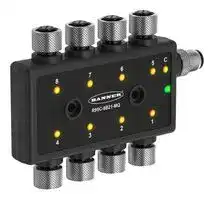


R95C-8B21-MQ
Signal Converter, NPN / PNP, Modbus, 1 Channels, 30 VDC
- Manufacturer: BANNER ENGINEERING
- Product type: Signal Converters
- SVHC: No SVHC (15-Jan-2018)
- Accuracy %: -
- Product Range: R95C Series
- Supply Voltage: 30VDC
- Isolation Input: -
- No. of Channels: 8 Channel
- Output Accuracy: -
- No. of Output Channels: 1Channels
- Signal Conditioner Input: NPN / PNP
- Signal Conditioner Output: Modbus
- Signal Conditioner Mounting: Screw Mount
| Delivery and price | |
|---|---|
| Units per pack | 1 |
| Price | 264.81 € |
| Current stock | 10+ |
| Lead time | 30 days |
R95C 8-Port Discrete Bimodal to Modbus[®] Hub

## Instruction Manual

- Compact bimodal to Modbus[®] device converter that connects discrete inputs and outputs the value

**==> picture [114 x 59] intentionally omitted <==**

- Enabled Delay Modes: ON/OFF Delay, ON/OFF One-shot, ON/OFF/ Retriggerable One-shot, ON/OFF Pulse-stretcher and Totalizer

- Measurement Metrics: Count, Events Per Minute (EPM), and Duration

- Discrete Mirroring: Discrete signals (In/Out) from all eight ports can be mirrored to any of the eight ports, Discrete Out, or the host white wire output

- Outputs a discrete value as an input to a defined Modbus register

- Discrete input/output can be independently configured as NPN or PNP

- Rugged over-molded design meets IP65, IP67, and IP68

- Connects directly to a sensor or anywhere in-line for ease of use

- R95C Modbus hubs are a quick, easy, and economical way to integrate nonModbus devices into a Modbus system

## Models

|**Housing**|**Function**|**Function**|**Function**|**Converter**|**Converter**|**Converter**|**Converter**|**Control**|**Control**|**Connector**|**Connector**|**Connector**|
|---|---|---|---|---|---|---|---|---|---|---|---|---|
|R95||C|||8B21|||M|||Q||
||C = Converter|||8B21 = 8-port,<br>M = Modbus||||||Q = M12 integral|||
|||||bimodal, 2||||||quick disconnect|||
|||||inputs,||1 output|||||||


## Overview

The R95C-8B21-MQ hub connects two discrete channels to each of the eight unique ports, providing access to monitoring and configuring those ports via Modbus[®] registers. Host mirroring is available where a selected port input/output discrete signal can be routed to Pin 5 (male) on the PLC/Host connection.

Original Document 231261 Rev. A

29 March 2023

231261

R95C 8-Port Discrete Bimodal to Modbus[®] Hub

## Configuration

The logic flow for **Pin 4 Selection** and **Pin 2 Selection** in the figure below is the same for all eight ports of the R95C 8-Port Hub.

_Figure 1. Logic Flow_

**==> picture [331 x 205] intentionally omitted <==**

**----- Start of picture text -----**<br>
Host  Enabled<br>Mirroring Host Mirroring<br>Enable<br>Host Mirroring – Discrete Host Out<br>• Port [1..8] / Pin [2/4] (F) state driven to Pin 5 (M)<br>Input<br>• npn Pin Mode<br>Pin 4 • pnp • Disabled<br>Selection • On Off Delay<br>• On One-shot Pins 2 and 4 – Ports 1 - 8<br>Pin 2 Input • npn• pnp • Off One-shot• On Pulse-Stretcher• Off Pulse-Stretcher Measurement Statistics • Active States• Count• EPM• Duration<br>• Totalizer<br>Selection<br>• Retriggerable On One-Shot<br>• Retriggerable Off One-Shot<br>Output<br>• npn.pull-up<br>• pnp.pull-up<br>• npn.push-pull<br>• pnp.push-pull<br>MirroringEnable Enabled Mirroring Mirroring - Pin 2 Output • Port [1..8] / Pin [2/4] (F) state driven to Pin 2 (F)<br>Disabled Pin 2 Data Output Pin 2 Output • Active/Inactive state driven to Pin 2 (F)<br>**----- End of picture text -----**<br>


_Table 1: Device Port States_

|**Modbus Register**<br>**Address**|**Description**|**I/O Range**|**Comments**|**Default**|**Access**|**Notes**|
|---|---|---|---|---|---|---|
|40001|Active States|0..65535|Port 1..Port 8 Outputs to Pin 4 and Pin 2<br>Active States|-|RO|One bit per port, or one bit per<br>Pin 2 and Pin 4|
|40002|Pin 2 Active State|0..255|Port 1..Port 8 Outputs to Pin 2 Output<br>State|0|RW|One bit per port, or one bit per<br>Pin 2|


_Table 2: Discrete Host Out Mirroring (Gray - Male)_

|**Modbus Register**<br>**Address**|**Description**|**I/O Range**|**Comments**|**Default**|**Access**|
|---|---|---|---|---|---|
|40100|Host Mirroring Enable|0..1|0 = Disable, 1 = Enable|0|RW|
|40101|Mirroring Port Selection|0..7|0 = Port 1<br>1 = Port 2<br>2 = Port 3<br>3 = Port 4<br>4 = Port 5<br>5 = Port 6<br>6 = Port 7<br>7 = Port 8|0|RW|
|40102|Host Mirroring Channel Selection|0..1|0 = Pin 1, 1 = Pin 5|0|RW|
|40103|Host Mirroring Inversion|0..1|0 = Not Inverted, 1 = Inverted|0|RW|
|40104|Host Mirroring Polarity|0..1|0 = NPN Output, 1 = PNP Output|0|RW|
|40105|Host Mirroring Output Type|0..2|0 = Output with Internal Pull Up/Down<br>1 = Output Open Collector<br>2 = Output Push Pull|0|RW|


_Table 3: Modbus Configuration_

|**Modbus Register**<br>**Address**|**Description**|**I/O Range**|**Comments**|**Default**|**Access**|
|---|---|---|---|---|---|
|40601|Baud Rate|0 = 9.6k<br>1 = 19.2k<br>2 = 38.4k|0 = 9600<br>1 = 19200<br>2 = 38400|1|RW|


P/N 231261 Rev. A

2

www.bannerengineering.com - Tel: + 1 888 373 6767

R95C 8-Port Discrete Bimodal to Modbus[®] Hub

|**Modbus Register**<br>**Address**|**Description**|**I/O Range**|**Comments**|**Default**|**Access**|
|---|---|---|---|---|---|
|40602|Parity|0 = None<br>1 = Odd<br>2 = Even|0 = None<br>1 = Odd<br>2 = Even|0|RW|
|40603|Address|1-254|-|1|RW|
|40604|Reserved (cannot be read or written)|None|-|-|RW|
|40605|Restore Factory Configuration|0 = No Operation, 1 = Restore|-|-|WO|


## _Table 4: Device Information_

|**Modbus Register**<br>**Address**|**Description**|**I/O Range**|**Comments**|**Default**|**Access**|**Notes**|
|---|---|---|---|---|---|---|
|40606-40615|Banner Name|0..65535|-|Banner Engineering|RO|9 words/18<br>Characters|
|40616-40631|Product Name|0..65535|-|R95C-8B21-MQ|RO|16 words/32<br>Characters|
|40632|Item H|0..65535|814251 split into two<br>16-bit registers|12|RO|Banner Item Number|
|40633|Item L|0..65535|-|27819|RO|-|
|40634|Serial Number H|0..65535|-|-|RO|Serial Number is split<br>into four 16-bit<br>registers|
|40635|Serial Number|0..65535|-|-|RO||
|40636|Serial Number|0..65535|-|-|RO|-|
|40637|Serial Number L|0..65535|-|-|RO|-|
|40644-40659|User Define Tag|0..65535|User writable space|More Sensors. More Solutions.|RW|16 words/32<br>Characters|


## Multi-Port Support

All register maps shown below are specific to port 1. For multi-port adapters, each port is given its own register range within the holding register space.

|**Register Range**|**Port Number**|
|---|---|
|41001-41401|Port 1|
|42001-42401|Port 2|
|43001-43401|Port 3|
|44001-44401|Port 4|
|45001-45401|Port 5|
|46001-46401|Port 6|
|47001-47401|Port 7|
|48001-48401|Port 8|


For a given register, the starting address of the port can be applied to determine the register address for the new port. For example, the calculation below demonstrates how to find the address of the process data output for port 8.

|**Equivalent Port 1 Register**|**Port**|**Port Starting Register**|**Offset**|**New Register**|
|---|---|---|---|---|
|41051|1|41001|50|41051|
|41051|8|48001|50|48051|


## Register Maps

_Table 5: Measurement Reads_

|**Modbus Register**<br>**Address**|**Description**|**I/O Range**|**Comments**|**Default**|**Access**|**Notes**|
|---|---|---|---|---|---|---|
|41001|Pin 4 Active State|0..1|0 = Inactive, 1 = Active|-|RO|-|
|41002|Pin 2 Active State|0..1|0 = Inactive, 1 = Active|-|RO|-|
|41003|Pin 4 Count H|0..65535|Pin 4 Count Value Upper|-|RO|Upper 16 of 32 bits =<br>Running count of the<br>received input pulses|


P/N 231261 Rev. A

www.bannerengineering.com - Tel: + 1 888 373 6767

3

R95C 8-Port Discrete Bimodal to Modbus[®] Hub

|**Modbus Register**<br>**Address**|**Description**|**I/O Range**|**Comments**|**Default**|**Access**|**Notes**|
|---|---|---|---|---|---|---|
|41004|Pin 4 Count L|0..65535|Pin 4 Count Value Lower|-|RO|Lower 16 of 32 bits =<br>Running count of the<br>received input pulses|
|41005|Pin 4 Duration H|0..65535|Pin 4 Duration Value Upper|-|RO|Upper 16 of 32 bits =<br>Duration of the last<br>input pulse in μs with<br>50 μs granularity|
|41006|Pin 4 Duration L|0..65535|Pin 4 Duration Value Lower|-|RO|Lower 16 of 32 bits =<br>Duration of the last<br>input pulse in μs with<br>50 μs granularity|
|41007|Pin 4 Events Per Minute H|0..65535|Pin 4 Events Per Minute Value Upper|-|RO|Upper 16 of 32 bits =<br>Running count of the<br>number of pulses<br>received averaged<br>over one minute<br>Range 1 to 37,500|
|41008|Pin 4 Events Per Minute L|0..65535|Pin 4 Events Per Minute Value Lower|-|RO|Lower 16 of 32 bits =<br>Running count of the<br>number of pulses<br>received averaged<br>over one minute<br>Range 1 to 37,500|
|41009|Pin 4 Totalizer Count H|0..65535|Pin 4 Totalizer Count Upper|-|RO|Upper 16 of 32 bits =<br>Totalizer Count|
|41010|Pin 4 Totalizer Count L|0..65535|Pin 4 Totalizer Count Lower|-|RO|Lower 16 of 32 bits =<br>Totalizer Count|
|41011|Pin 2 Count H|0..65535|Pin 2 Count Value Upper|-|RO|Upper 16 of 32 bits =<br>Running count of the<br>received input pulses|
|41012|Pin 2 Count L|0..65535|Pin 2 Count Value Lower|-|RO|Lower 16 of 32 bits =<br>Running count of the<br>received input pulses|
|41013|Pin 2 Duration H|0..65535|Pin 2 Duration Value Upper|-|RO|Upper 16 of 32 bits =<br>Duration of the last<br>input pulse in μs with<br>50 μs granularity|
|41014|Pin 2 Duration L|0..65535|Pin 2 Duration Value Lower|-|RO|Lower 16 of 32 bits =<br>Duration of the last<br>input pulse in μs with<br>50 μs granularity|
|41015|Pin 2 Events Per Minute H|0..65535|Pin 2 Events Per Minute Value Upper|-|RO|Upper 16 of 32 bits =<br>Running count of the<br>number of pulses<br>received averaged<br>over one minute<br>Range: 1 to 37,500|
|41016|Pin 2 Events Per Minute L|0..65535|Pin 2 Events Per Minute Value Lower|-|RO|Lower 16 of 32 bits =<br>Running count of the<br>number of pulses<br>received averaged<br>over one minute<br>Range: 1 to 37,500|
|41017|Pin 2 Totalizer Count H|0..65535|Pin 2 Totalizer Count Upper|-|RO|Upper 16 of 32 bits =<br>Totalizer Count|
|41018|Pin 2 Totalizer Count L|0..65535|Pin 2 Totalizer Count Lower|-|RO|Lower 16 of 32 bits =<br>Totalizer Count|


P/N 231261 Rev. A

www.bannerengineering.com - Tel: + 1 888 373 6767

4

R95C 8-Port Discrete Bimodal to Modbus[®] Hub

_Table 6: Metric Count Presets_

|**Modbus Register**<br>**Address**|**Description**|**I/O Range**|**Comments**|**Default**|**Access**|
|---|---|---|---|---|---|
|41100|Pin 4 Count H|0..65535|Pin 4 Count Value Upper|-|RW|
|41101|Pin 4 Count L|0..65535|Pin 4 Count Value Lower|-|RW|
|41102|Pin 2 Count H|0..65535|Pin 2 Count Value Upper|-|RW|
|41103|Pin 2 Count L|0..65535|Pin 2 Count Value Lower|-|RW|


_Table 7: Pin 4 Port Configuration (Black - Female, Discrete 1)_

|**Modbus Register**<br>**Address**|**Description**|**I/O Range**|**Comments**|**Default**|**Access**|**Notes**|
|---|---|---|---|---|---|---|
|41200|Pin 4 IO Selection|0..5|0 = NPN input, 1 = PNP input|0|RW|-|
|41201|Pin 4 Mode|0..8|0 = Disabled<br>1 = On Off Delay<br>2 = On One-shot<br>3 = Off One-shot<br>4 = On Pulse-stretcher<br>5 = Off Pulse-stretcher<br>6 = Totalizer<br>7 = Retriggerable On One-shot<br>8 = Retriggerable Off One-shot|0|RW|-|
|41202|Pin 4 Delay Timer 1 Upper|0..65535|Pin 4 On Delay, One-shot, Pulse-<br>stretcher time, Totalizer Count|0|RW|Upper 16 of 32 Bits:<br>Mode 1, 2, 3, 4, 5, 7, 8 =<br>Milliseconds<br>Mode 6 = Count|
|41203|Pin 4 Delay Timer 1 Lower|0..65535|Pin 4 On Delay, One-shot, Pulse-<br>stretcher time, Totalizer Count|0|RW|Lower 16 of 32 Bits:<br>Mode 1, 2, 3, 4, 5, 7, 8 =<br>Milliseconds<br>Mode 6 = Count|
|41204|Pin 4 Delay Timer 2 Upper|0..65535|Pin 4 Off Delay or Totalizer time|0|RW|Upper 16 of 32 Bits =<br>Milliseconds|
|41205|Pin 4 Delay Timer 2 Lower|0..65535|Pin 4 Off Delay or Totalizer time|0|RW|Lower 16 of 32 Bits =<br>Milliseconds|


_Table 8: Pin 2 Port Configuration (White - Female, Discrete 2)_

|**Modbus Register**<br>**Address**|**Description**|**I/O Range**|**Comments**|**Default**|**Access**|**Notes**|
|---|---|---|---|---|---|---|
|41300|Pin 2 IO Selection|0..5|0 = NPN input<br>1 = PNP input<br>2 = NPN output with pull up<br>3 = PNP output with pull down<br>4 = NPN output push/pull<br>5 = PNP output push/pull|0|RW|-|
|41301|Pin 2 Mode|0..6|0 = Disabled<br>1 = On Off Delay<br>2 = On One-shot<br>3 = Off One-shot<br>4 = On Pulse-stretcher<br>5 = Off Pulse-stretcher<br>6 = Totalizer<br>7 = Retriggerable On One-shot<br>8 = Retriggerable Off One-shot|0|RW|-|
|41302|Pin 2 Delay Timer 1 Upper|0..65535|Pin 2 On Delay, One-shot, Pulse-<br>stretcher time, or Totalizer Count|0|RW|Upper 16 of 32 Bits:<br>Mode 1, 2, 3, 4, 5, 7, 8 =<br>Milliseconds<br>Mode 6 = Count|
|41303|Pin 2 Delay Timer 1 Lower|0..65535|Pin 2 On Delay, One-shot, Pulse-<br>stretcher time, or Totalizer Count|0|RW|Lower 16 of 32 Bits:<br>Mode 1, 2, 3, 4, 5, 7, 8 =<br>Milliseconds<br>Mode 6 = Count|
|41304|Pin 2 Delay Timer 2 Upper|0..65535|Pin 2 Off Delay or Totalizer time|0|RW|Upper 16 of 32 Bits =<br>Milliseconds|


P/N 231261 Rev. A

www.bannerengineering.com - Tel: + 1 888 373 6767

5

R95C 8-Port Discrete Bimodal to Modbus[®] Hub

|**Modbus Register**<br>**Address**|**Description**|**I/O Range**|**Comments**|**Default**|**Access**|**Notes**|
|---|---|---|---|---|---|---|
|41305|Pin 2 Delay Timer 2 Lower|0..65535|Pin 2 Off Delay or Totalizer time|0|RW|Lower 16 of 32 Bits =<br>Milliseconds|
|41306|Pin 2 Mirroring Enable|0..1|0 = Disabled, 1 = Enabled|0|RW|-|
|41307|Mirroring Port Selection|0..7|0 = Port 1<br>1 = Port 2<br>2 = Port 3<br>3 = Port 4<br>4 = Port 5<br>5 = Port 6<br>6 = Port 7<br>7 = Port 8|0|RW|-|
|41308|Pin 2 Mirroring Selection|0..1|0 = Pin 4, 1 = Pin 2|0|RW|-|
|41309|Pin 2 Mirroring Inversion|0..1|0 = Not Inverted, 1 = Inverted|0|RW|-|


_Table 9: Active Configurations_

|**Modbus Register**<br>**Address**|**Description**|**I/O Range**|**Comments**|**Default**|**Access**|**Notes**|
|---|---|---|---|---|---|---|
|41401|Pin 2 Data Output|0..1|0 = Inactive, 1 = Active|0|RW|If mirroring is disabled and<br>IO selection is set to output,<br>Data Output is set to<br>inactive/active|


## Alias Registers

When reading an alias register, the data in the register is filled with the contents of the address that are present in the corresponding alias configuration register. The address can be stored in either direct or modicon addressing. Note that Read-Only aliased registers are read-only, and it is not possible to write to an alias Read-Only register.

## Read-Only Registers and Addresses

By default, the read-only alias registers are configured to point to the active state status and count registers for Pin 2 and Pin 4 for all 8 ports.

Any alias registers that are configured to an unsupported register address, or where the read operation fails for some other reason, returns as a zero when read.

All Alias RO registers are part of Alias assignments.

_Table 10: Alias RO Registers_

|**Modbus Register**<br>**Address**|**Description**|**I/O Range**|**Comments**|**Default**|**Access**|
|---|---|---|---|---|---|
|40501|Port 1 Pin 4 Active State|0..1|0 = Inactive, 1 = Active|-|RO|
|40502|Port 1 Pin 2 Active State|0..1|0 = Inactive, 1 = Active|-|RO|
|40503|Port 2 Pin 4 Active State|0..1|0 = Inactive, 1 = Active|-|RO|
|40504|Port 2 Pin 2 Active State|0..1|0 = Inactive, 1 = Active|-|RO|
|40505|Port 3 Pin 4 Active State|0..1|0 = Inactive, 1 = Active|-|RO|
|40506|Port 3 Pin 2 Active State|0..1|0 = Inactive, 1 = Active|-|RO|
|40507|Port 4 Pin 4 Active State|0..1|0 = Inactive, 1 = Active|-|RO|
|40508|Port 4 Pin 2 Active State|0..1|0 = Inactive, 1 = Active|-|RO|
|40509|Port 5 Pin 4 Active State|0..1|0 = Inactive, 1 = Active|-|RO|
|40510|Port 5 Pin 2 Active State|0..1|0 = Inactive, 1 = Active|-|RO|
|40511|Port 6 Pin 4 Active State|0..1|0 = Inactive, 1 = Active|-|RO|
|40512|Port 6 Pin 2 Active State|0..1|0 = Inactive, 1 = Active|-|RO|
|40513|Port 7 Pin 4 Active State|0..1|0 = Inactive, 1 = Active|-|RO|
|40514|Port 7 Pin 2 Active State|0..1|0 = Inactive, 1 = Active|-|RO|
|40515|Port 8 Pin 4 Active State|0..1|0 = Inactive, 1 = Active|-|RO|
|40516|Port 8 Pin 2 Active State|0..1|0 = Inactive, 1 = Active|-|RO|
|40517|Port 1 Pin 4 Count H|0..65535|Port 1 Pin 4 Count Value Upper|-|RO|
|40518|Port 1 Pin 4 Count L|0..65535|Port 1 Pin 4 Count Value Lower|-|RO|


P/N 231261 Rev. A

6

www.bannerengineering.com - Tel: + 1 888 373 6767

R95C 8-Port Discrete Bimodal to Modbus[®] Hub

|**Modbus Register**<br>**Address**|**Description**|**I/O Range**|**Comments**|**Default**|**Access**|
|---|---|---|---|---|---|
|40519|Port 2 Pin 4 Count H|0..65535|Port 2 Pin 4 Count Value Upper|-|RO|
|40520|Port 2 Pin 4 Count L|0..65535|Port 2 Pin 4 Count Value Lower|-|RO|
|40521|Port 3 Pin 4 Count H|0..65535|Port 3 Pin 4 Count Value Upper|-|RO|
|40522|Port 3 Pin 4 Count L|0..65535|Port 3 Pin 4 Count Value Lower|-|RO|
|40523|Port 4 Pin 4 Count H|0..65535|Port 4 Pin 4 Count Value Upper|-|RO|
|40524|Port 4 Pin 4 Count L|0..65535|Port 4 Pin 4 Count Value Lower|-|RO|
|40525|Port 5 Pin 4 Count H|0..65535|Port 5 Pin 4 Count Value Upper|-|RO|
|40526|Port 5 Pin 4 Count L|0..65535|Port 5 Pin 4 Count Value Lower|-|RO|
|40527|Port 6 Pin 4 Count H|0..65535|Port 6 Pin 4 Count Value Upper|-|RO|
|40528|Port 6 Pin 4 Count L|0..65535|Port 6 Pin 4 Count Value Lower|-|RO|
|40529|Port 7 Pin 4 Count H|0..65535|Port 7 Pin 4 Count Value Upper|-|RO|
|40530|Port 7 Pin 4 Count L|0..65535|Port 7 Pin 4 Count Value Lower|-|RO|
|40531|Port 8 Pin 4 Count H|0..65535|Port 8 Pin 4 Count Value Upper|-|RO|
|40532|Port 8 Pin 4 Count L|0..65535|Port 8 Pin 4 Count Value Lower|-|RO|
|40533|Port 1 Pin 2 Count H|0..65535|Port 1 Pin 2 Count Value Upper|-|RO|
|40534|Port 1 Pin 2 Count L|0..65535|Port 1 Pin 2 Count Value Lower|-|RO|
|40535|Port 2 Pin 2 Count H|0..65535|Port 2 Pin 2 Count Value Upper|-|RO|
|40536|Port 2 Pin 2 Count L|0..65535|Port 2 Pin 2 Count Value Lower|-|RO|
|40537|Port 3 Pin 2 Count H|0..65535|Port 3 Pin 2 Count Value Upper|-|RO|
|40538|Port 3 Pin 2 Count L|0..65535|Port 3 Pin 2 Count Value Lower|-|RO|
|40539|Port 4 Pin 2 Count H|0..65535|Port 4 Pin 2 Count Value Upper|-|RO|
|40540|Port 4 Pin 2 Count L|0..65535|Port 4 Pin 2 Count Value Lower|-|RO|
|40541|Port 5 Pin 2 Count H|0..65535|Port 5 Pin 2 Count Value Upper|-|RO|
|40542|Port 5 Pin 2 Count L|0..65535|Port 5 Pin 2 Count Value Lower|-|RO|
|40543|Port 6 Pin 2 Count H|0..65535|Port 6 Pin 2 Count Value Upper|-|RO|
|40544|Port 6 Pin 2 Count L|0..65535|Port 6 Pin 2 Count Value Lower|-|RO|
|40545|Port 7 Pin 2 Count H|0..65535|Port 7 Pin 2 Count Value Upper|-|RO|
|40546|Port 7 Pin 2 Count L|0..65535|Port 7 Pin 2 Count Value Lower|-|RO|
|40547|Port 8 Pin 2 Count H|0..65535|Port 8 Pin 2 Count Value Upper|-|RO|
|40548|Port 8 Pin 2 Count L|0..65535|Port 8 Pin 2 Count Value Lower|-|RO|


_Table 11: Alias Read-Only Addresses_

|**Modbus Register**<br>**Address**|**Description**|**I/O Range**|**Comments**|**Default**|**Access**|
|---|---|---|---|---|---|
|40701|Alias Register Address|0..65535|Value shows up in 40501|41001|RW|
|40702|Alias Register Address|0..65535|Value shows up in 40502|41002|RW|
|40703|Alias Register Address|0..65535|Value shows up in 40503|42001|RW|
|40704|Alias Register Address|0..65535|Value shows up in 40504|42002|RW|
|40705|Alias Register Address|0..65535|Value shows up in 40505|43001|RW|
|40706|Alias Register Address|0..65535|Value shows up in 40506|43002|RW|
|40707|Alias Register Address|0..65535|Value shows up in 40507|44001|RW|
|40708|Alias Register Address|0..65535|Value shows up in 40508|44002|RW|
|40709|Alias Register Address|0..65535|Value shows up in 40509|45001|RW|
|40710|Alias Register Address|0..65535|Value shows up in 40510|45002|RW|
|40711|Alias Register Address|0..65535|Value shows up in 40511|46001|RW|
|40712|Alias Register Address|0..65535|Value shows up in 40512|46002|RW|
|40713|Alias Register Address|0..65535|Value shows up in 40513|47001|RW|
|40714|Alias Register Address|0..65535|Value shows up in 40514|47002|RW|
|40715|Alias Register Address|0..65535|Value shows up in 40515|48001|RW|


P/N 231261 Rev. A

www.bannerengineering.com - Tel: + 1 888 373 6767

7

R95C 8-Port Discrete Bimodal to Modbus[®] Hub

|**Modbus Register**<br>**Address**|**Description**|**I/O Range**|**Comments**|**Default**|**Access**|
|---|---|---|---|---|---|
|40716|Alias Register Address|0..65535|Value shows up in 40516|48002|RW|
|40717|Alias Register Address|0..65535|Value shows up in 40517|41003|RW|
|40718|Alias Register Address|0..65535|Value shows up in 40518|41004|RW|
|40719|Alias Register Address|0..65535|Value shows up in 40519|42003|RW|
|40720|Alias Register Address|0..65535|Value shows up in 40520|42004|RW|
|40721|Alias Register Address|0..65535|Value shows up in 40521|43003|RW|
|40722|Alias Register Address|0..65535|Value shows up in 40522|43004|RW|
|40723|Alias Register Address|0..65535|Value shows up in 40523|44003|RW|
|40724|Alias Register Address|0..65535|Value shows up in 40524|44004|RW|
|40725|Alias Register Address|0..65535|Value shows up in 40525|45003|RW|
|40726|Alias Register Address|0..65535|Value shows up in 40526|45004|RW|
|40727|Alias Register Address|0..65535|Value shows up in 40527|46003|RW|
|40728|Alias Register Address|0..65535|Value shows up in 40528|46004|RW|
|40729|Alias Register Address|0..65535|Value shows up in 40529|47003|RW|
|40730|Alias Register Address|0..65535|Value shows up in 40530|47004|RW|
|40731|Alias Register Address|0..65535|Value shows up in 40531|48003|RW|
|40732|Alias Register Address|0..65535|Value shows up in 40532|48004|RW|
|40733|Alias Register Address|0..65535|Value shows up in 40533|41011|RW|
|40734|Alias Register Address|0..65535|Value shows up in 40534|41012|RW|
|40735|Alias Register Address|0..65535|Value shows up in 40535|42011|RW|
|40736|Alias Register Address|0..65535|Value shows up in 40536|42012|RW|
|40737|Alias Register Address|0..65535|Value shows up in 40537|43011|RW|
|40738|Alias Register Address|0..65535|Value shows up in 40538|43012|RW|
|40739|Alias Register Address|0..65535|Value shows up in 40539|44011|RW|
|40740|Alias Register Address|0..65535|Value shows up in 40540|44012|RW|
|40741|Alias Register Address|0..65535|Value shows up in 40541|45011|RW|
|40742|Alias Register Address|0..65535|Value shows up in 40542|45012|RW|
|40743|Alias Register Address|0..65535|Value shows up in 40543|46011|RW|
|40744|Alias Register Address|0..65535|Value shows up in 40544|46012|RW|
|40745|Alias Register Address|0..65535|Value shows up in 40545|47011|RW|
|40746|Alias Register Address|0..65535|Value shows up in 40546|47012|RW|
|40747|Alias Register Address|0..65535|Value shows up in 40547|48011|RW|
|40748|Alias Register Address|0..65535|Value shows up in 40548|48012|RW|


## Read-Write Alias Registers and Addresses

By default, the read-write alias registers are configured to point to the Pin 2 output data and Pin 2 and Pin 4 metric count preset registers for all 8 ports.

If writing to an alias register fails (for example, if the aliased register is not writeable), then the write operation of the alias registers will NACK.

A register value that is set to 65535 is always read as 0, and no write operation will be attempted.

All Alias RW registers are part of RW Alias assignments.

_Table 12: Alias RW Registers_

|**Modbus Register**<br>**Address**|**Description**|**I/O Range**|**Comments**|**Default**|**Access**|
|---|---|---|---|---|---|
|40801|Port 1 Pin 2 Data Output|0..1|0 = Inactive, 1 = Active|0|RW|
|40802|Port 2 Pin 2 Data Output|0..1|0 = Inactive, 1 = Active|0|RW|
|40803|Port 3 Pin 2 Data Output|0..1|0 = Inactive, 1 = Active|0|RW|
|40804|Port 4 Pin 2 Data Output|0..1|0 = Inactive, 1 = Active|0|RW|
|40805|Port 5 Pin 2 Data Output|0..1|0 = Inactive, 1 = Active|0|RW|
|40806|Port 6 Pin 2 Data Output|0..1|0 = Inactive, 1 = Active|0|RW|


P/N 231261 Rev. A

8

www.bannerengineering.com - Tel: + 1 888 373 6767

R95C 8-Port Discrete Bimodal to Modbus[®] Hub

|**Modbus Register**<br>**Address**|**Description**|**I/O Range**|**Comments**|**Default**|**Access**|
|---|---|---|---|---|---|
|40807|Port 7 Pin 2 Data Output|0..1|0 = Inactive, 1 = Active|0|RW|
|40808|Port 8 Pin 2 Data Output|0..1|0 = Inactive, 1 = Active|0|RW|
|40809|Port 1 Pin 4 Count H|0..65535|Pin 4 Count Value Upper|-|RW|
|40810|Port 1 Pin 4 Count L|0..65535|Pin 4 Count Value Lower|-|RW|
|40811|Port 2 Pin 4 Count H|0..65535|Pin 4 Count Value Upper|-|RW|
|40812|Port 2 Pin 4 Count L|0..65535|Pin 4 Count Value Lower|-|RW|
|40813|Port 3 Pin 4 Count H|0..65535|Pin 4 Count Value Upper|-|RW|
|40814|Port 3 Pin 4 Count L|0..65535|Pin 4 Count Value Lower|-|RW|
|40815|Port 4 Pin 4 Count H|0..65535|Pin 4 Count Value Upper|-|RW|
|40816|Port 4 Pin 4 Count L|0..65535|Pin 4 Count Value Lower|-|RW|
|40817|Port 5 Pin 4 Count H|0..65535|Pin 4 Count Value Upper|-|RW|
|40818|Port 5 Pin 4 Count L|0..65535|Pin 4 Count Value Lower|-|RW|
|40819|Port 6 Pin 4 Count H|0..65535|Pin 4 Count Value Upper|-|RW|
|40820|Port 6 Pin 4 Count L|0..65535|Pin 4 Count Value Lower|-|RW|
|40821|Port 7 Pin 4 Count H|0..65535|Pin 4 Count Value Upper|-|RW|
|40822|Port 7 Pin 4 Count L|0..65535|Pin 4 Count Value Lower|-|RW|
|40823|Port 8 Pin 4 Count H|0..65535|Pin 4 Count Value Upper|-|RW|
|40824|Port 8 Pin 4 Count L|0..65535|Pin 4 Count Value Lower|-|RW|
|40825|Port 1 Pin 2 Count H|0..65535|Pin 2 Count Value Upper|-|RW|
|40826|Port 1 Pin 2 Count L|0..65535|Pin 2 Count Value Lower|-|RW|
|40827|Port 2 Pin 2 Count H|0..65535|Pin 2 Count Value Upper|-|RW|
|40828|Port 2 Pin 2 Count L|0..65535|Pin 2 Count Value Lower|-|RW|
|40829|Port 3 Pin 2 Count H|0..65535|Pin 2 Count Value Upper|-|RW|
|40830|Port 3 Pin 2 Count L|0..65535|Pin 2 Count Value Lower|-|RW|
|40831|Port 4 Pin 2 Count H|0..65535|Pin 2 Count Value Upper|-|RW|
|40832|Port 4 Pin 2 Count L|0..65535|Pin 2 Count Value Lower|-|RW|
|40833|Port 5 Pin 2 Count H|0..65535|Pin 2 Count Value Upper|-|RW|
|40834|Port 5 Pin 2 Count L|0..65535|Pin 2 Count Value Lower|-|RW|
|40835|Port 6 Pin 2 Count H|0..65535|Pin 2 Count Value Upper|-|RW|
|40836|Port 6 Pin 2 Count L|0..65535|Pin 2 Count Value Lower|-|RW|
|40837|Port 7 Pin 2 Count H|0..65535|Pin 2 Count Value Upper|-|RW|
|40838|Port 7 Pin 2 Count L|0..65535|Pin 2 Count Value Lower|-|RW|
|40839|Port 8 Pin 2 Count H|0..65535|Pin 2 Count Value Upper|-|RW|
|40840|Port 8 Pin 2 Count L|0..65535|Pin 2 Count Value Lower|-|RW|


_Table 13: Alias Read-Write Addresses_

|**Modbus Register**<br>**Address**|**Description**|**I/O Range**|**Comments**|**Default**|**Access**|
|---|---|---|---|---|---|
|40901|Alias Register Address|0..65535|Value shows up in 40801|41401|RW|
|40902|Alias Register Address|0..65535|Value shows up in 40802|42401|RW|
|40903|Alias Register Address|0..65535|Value shows up in 40803|43401|RW|
|40904|Alias Register Address|0..65535|Value shows up in 40804|44401|RW|
|40905|Alias Register Address|0..65535|Value shows up in 40805|45401|RW|
|40906|Alias Register Address|0..65535|Value shows up in 40806|46401|RW|
|40907|Alias Register Address|0..65535|Value shows up in 40807|47401|RW|
|40908|Alias Register Address|0..65535|Value shows up in 40808|48401|RW|
|40909|Alias Register Address|0..65535|Value shows up in 40809|41100|RW|
|40910|Alias Register Address|0..65535|Value shows up in 40810|41101|RW|
|40911|Alias Register Address|0..65535|Value shows up in 40811|42100|RW|


P/N 231261 Rev. A

www.bannerengineering.com - Tel: + 1 888 373 6767

9

R95C 8-Port Discrete Bimodal to Modbus[®] Hub

|**Modbus Register**<br>**Address**|**Description**|**I/O Range**|**Comments**|**Default**|**Access**|
|---|---|---|---|---|---|
|40912|Alias Register Address|0..65535|Value shows up in 40812|42101|RW|
|40913|Alias Register Address|0..65535|Value shows up in 40813|43100|RW|
|40914|Alias Register Address|0..65535|Value shows up in 40814|43101|RW|
|40915|Alias Register Address|0..65535|Value shows up in 40815|44100|RW|
|40916|Alias Register Address|0..65535|Value shows up in 40816|44101|RW|
|40917|Alias Register Address|0..65535|Value shows up in 40817|45100|RW|
|40918|Alias Register Address|0..65535|Value shows up in 40818|45101|RW|
|40919|Alias Register Address|0..65535|Value shows up in 40819|46100|RW|
|40920|Alias Register Address|0..65535|Value shows up in 40820|46101|RW|
|40921|Alias Register Address|0..65535|Value shows up in 40821|47100|RW|
|40922|Alias Register Address|0..65535|Value shows up in 40822|47101|RW|
|40923|Alias Register Address|0..65535|Value shows up in 40823|48100|RW|
|40924|Alias Register Address|0..65535|Value shows up in 40824|48101|RW|
|40925|Alias Register Address|0..65535|Value shows up in 40825|41102|RW|
|40926|Alias Register Address|0..65535|Value shows up in 40826|41103|RW|
|40927|Alias Register Address|0..65535|Value shows up in 40827|42102|RW|
|40928|Alias Register Address|0..65535|Value shows up in 40828|42103|RW|
|40929|Alias Register Address|0..65535|Value shows up in 40829|43102|RW|
|40930|Alias Register Address|0..65535|Value shows up in 40830|43103|RW|
|40931|Alias Register Address|0..65535|Value shows up in 40831|44102|RW|
|40932|Alias Register Address|0..65535|Value shows up in 40832|44103|RW|
|40933|Alias Register Address|0..65535|Value shows up in 40833|45102|RW|
|40934|Alias Register Address|0..65535|Value shows up in 40834|45103|RW|
|40935|Alias Register Address|0..65535|Value shows up in 40835|46102|RW|
|40936|Alias Register Address|0..65535|Value shows up in 40836|46103|RW|
|40937|Alias Register Address|0..65535|Value shows up in 40837|47102|RW|
|40938|Alias Register Address|0..65535|Value shows up in 40838|47103|RW|
|40939|Alias Register Address|0..65535|Value shows up in 40839|48102|RW|
|40940|Alias Register Address|0..65535|Value shows up in 40840|48103|RW|


## Mechanical Installation

Install the R95C 8-Port Hub to allow access for functional checks, maintenance, and service or replacement. Do not install the R95C 8-Port Hub in such a way to allow for intentional defeat.

All mounting hardware is supplied by the user. Fasteners must be of sufficient strength to guard against breakage. Use of permanent fasteners or locking hardware is recommended to prevent the loosening or displacement of the device. The mounting hole (4.5 mm) in the R95C 8-Port Hub accepts M4 (#8) hardware. See the figure below to help in determining the minimum screw length.

## MOUNTING SCREW

**==> picture [37 x 38] intentionally omitted <==**

**==> picture [36 x 9] intentionally omitted <==**

**----- Start of picture text -----**<br>
17.0 mm<br>**----- End of picture text -----**<br>


**CAUTION:** Do not overtighten the R95C 8-Port Hub's mounting screw during installation. Overtightening can affect the performance of the R95C 8-Port Hub.

P/N 231261 Rev. A

10

www.bannerengineering.com - Tel: + 1 888 373 6767

R95C 8-Port Discrete Bimodal to Modbus[®] Hub

## Wiring

|**Port 1-Port 8 — Female**|**Pin**|**Signal Description**|
|---|---|---|
|**2**<br>**3**<br>**4**<br>**1**|1|12 V DC to 30 V DC|
||2|Discrete 2 (IN/OUT)|
||3|Ground|
||4|Discrete 1 (IN)|
||||
|**Male**|**Pin**|**Signal Description**|
|**1**<br>**4**<br>**5**<br>**3**<br>**2**|1|12 V DC to 30 V DC|
||2|RS485/D1/B/+|
||3|Ground|
||4|RS485/D0/A/-|
||5|Banner 1-wire|


## Status Indicators

The R95C 8-Port Discrete Bimodal to Modbus[®] Hub has matching amber LED indicators on both sides for each discrete device port to allow for installation needs and still provide adequate indication visibility. There is also an additional amber LED indicator on both sides of the converter, which is specific to Modbus communication.

**==> picture [251 x 99] intentionally omitted <==**

**----- Start of picture text -----**<br>
Com LED<br>(x1 near M12 male)<br>8 7 6 5<br>Power LED<br>4 3 2 1 (x1 near M12 male)<br>Device LEDs<br>(x8)<br>**----- End of picture text -----**<br>


||**Discrete Device Amber LEDs**|**Discrete Device Amber LEDs**|||**Power Indicator Green LED**|||
|---|---|---|---|---|---|---|---|
||**Indication**|**Status**|||**Indication**|**Status**||
||Off|Discrete OUT is inactive|||Off|Power off||
||Solid Amber|Discrete OUT is active|||Solid Green|Power on||
|||||||||
||**Modbus Communication Amber LED**|||||||
||**Indication**||**Status**|||||
||Off||Modbus communications are not present|||||
||Flashing Amber (4 Hz)||Modbus communications are active|||||
||Solid Amber for 2 Seconds, Then to Off||Modbus communications are lost after connection|||||
||Solid Amber for 2 Seconds, Then to Flashing Amber (4 Hz)||Modbus communications momentarily lost, but then communication was reestablished|||||


P/N 231261 Rev. A

www.bannerengineering.com - Tel: + 1 888 373 6767

11

R95C 8-Port Discrete Bimodal to Modbus[®] Hub

## Specifications

**Supply Voltage** 12 V DC to 30 V DC at 400 mA maximum

**Power Pass-Through Current** 500 mA per port maximum

**Discrete Output Load Rating** 100 mA

## **Supply Protection Circuitry**

**Environmental Rating** IP65, IP67, IP68 UL Type 1

## **Operating Conditions**

**Temperature:** –40 °C to +70 °C (–40 °F to +158 °F) 90% at +70 °C maximum relative humidity (non-condensing) **Storage Temperature:** –40 °C to +80 °C (–40 °F to +176 °F)

## **Required Overcurrent Protection**

Protected against reverse polarity and transient voltages

## **Leakage Current Immunity**

400 µA

## **Indicators**

Green: Power Amber: Modbus communications Amber: Discrete OUT status

## **Connections**

(8) Integral 4-pin M12 female quick disconnect

(1) Integral 5-pin M12 male quick-disconnect connector

## **Construction**

Coupling Material: Nickel-plated brass Connector Body: PVC translucent black

## **Vibration and Mechanical Shock**

Meets IEC 60068-2-6 requirements (Vibration: 10 Hz to 55 Hz, 0.5 mm amplitude, 5 minutes sweep, 30 minutes dwell) Meets IEC 60068-2-27 requirements (Shock: 15G 11 ms duration, half sine wave)

## **Certifications**

**==> picture [32 x 56] intentionally omitted <==**

**Banner Engineering BV** Park Lane, Culliganlaan 2F bus 3, 1831 Diegem, BELGIUM

**Turck Banner LTD** Blenheim House, Blenheim Court, Wickford, Essex SS11 8YT, Great Britain

**WARNING:** Electrical connections must be made by qualified personnel in accordance with local and national electrical codes and regulations.

Overcurrent protection is required to be provided by end product application per the supplied table.

Overcurrent protection may be provided with external fusing or via Current Limiting, Class 2 Power Supply.

Supply wiring leads < 24 AWG shall not be spliced.

For additional product support, go to www.bannerengineering.com.

|**Supply Wiring (AWG)**|**Required Overcurrent Protection (Amps)**|
|---|---|
|20|5.0|
|22|3.0|
|24|2.0|
|26|1.0|
|28|0.8|
|30|0.5|


P/N 231261 Rev. A

12

www.bannerengineering.com - Tel: + 1 888 373 6767

R95C 8-Port Discrete Bimodal to Modbus[®] Hub

## Dimensions

All measurements are listed in millimeters [inches], unless noted otherwise.

**==> picture [35 x 38] intentionally omitted <==**

## Accessories

## Cordsets

|**4-Pin Threaded M12 Cordsets—Double Ended**|**4-Pin Threaded M12 Cordsets—Double Ended**|**4-Pin Threaded M12 Cordsets—Double Ended**|**4-Pin Threaded M12 Cordsets—Double Ended**|||
|---|---|---|---|---|---|
|**Model**|**Length**|**Style**|**Dimensio**|**ns**|**Pinout**|
|**MQDEC-401SS**|0.31 m (1 ft)|Male Straight/<br>Female Straight|40 Typ.<br>[1.58"]<br>ø 14.5 [0.57"]<br>M12 x 1<br>44 Typ.<br>[1.73"]<br>ø 14.5 [0.57"]<br>M12 x 1||Female<br>**2**<br>**3**<br>**4**<br>**1**<br>Male<br>**1**<br>**4**<br>**3**<br>**2**<br>1 = Brown<br>2 = White<br>3 = Blue<br>4 = Black|
|**MQDEC-403SS**|0.91 m (2.99 ft)|||||
|**MQDEC-406SS**|1.83 m (6 ft)|||||
|**MQDEC-412SS**|3.66 m (12 ft)|||||
|**MQDEC-420SS**|6.10 m (20 ft)|||||
|**MQDEC-430SS**|9.14 m (30.2 ft)|||||
|**MQDEC-450SS**|15.2 m (49.9 ft)|||||


## Banner Engineering Corp Limited Warranty

Banner Engineering Corp. warrants its products to be free from defects in material and workmanship for one year following the date of shipment. Banner Engineering Corp. will repair or replace, free of charge, any product of its manufacture which, at the time it is returned to the factory, is found to have been defective during the warranty period. This warranty does not cover damage or liability for misuse, abuse, or the improper application or installation of the Banner product.

P/N 231261 Rev. A

www.bannerengineering.com - Tel: + 1 888 373 6767

13

R95C 8-Port Discrete Bimodal to Modbus[®] Hub

**THIS LIMITED WARRANTY IS EXCLUSIVE AND IN LIEU OF ALL OTHER WARRANTIES WHETHER EXPRESS OR IMPLIED (INCLUDING, WITHOUT LIMITATION, ANY WARRANTY OF MERCHANTABILITY OR FITNESS FOR A PARTICULAR PURPOSE), AND WHETHER ARISING UNDER COURSE OF PERFORMANCE, COURSE OF DEALING OR TRADE USAGE.**

This Warranty is exclusive and limited to repair or, at the discretion of Banner Engineering Corp., replacement. **IN NO EVENT SHALL BANNER ENGINEERING CORP. BE LIABLE TO BUYER OR ANY OTHER PERSON OR ENTITY FOR ANY EXTRA COSTS, EXPENSES, LOSSES, LOSS OF PROFITS, OR ANY INCIDENTAL, CONSEQUENTIAL OR SPECIAL DAMAGES RESULTING FROM ANY PRODUCT DEFECT OR FROM THE USE OR INABILITY TO USE THE PRODUCT, WHETHER ARISING IN CONTRACT OR WARRANTY, STATUTE, TORT, STRICT LIABILITY, NEGLIGENCE, OR OTHERWISE.**

Banner Engineering Corp. reserves the right to change, modify or improve the design of the product without assuming any obligations or liabilities relating to any product previously manufactured by Banner Engineering Corp. Any misuse, abuse, or improper application or installation of this product or use of the product for personal protection applications when the product is identified as not intended for such purposes will void the product warranty. Any modifications to this product without prior express approval by Banner Engineering Corp will void the product warranties. All specifications published in this document are subject to change; Banner reserves the right to modify product specifications or update documentation at any time. Specifications and product information in English supersede that which is provided in any other language. For the most recent version of any documentation, refer to: www.bannerengineering.com.

For patent information, see www.bannerengineering.com/patents.

## FCC Part 15 Class B

This equipment has been tested and found to comply with the limits for a Class B digital device, pursuant to part 15 of the FCC Rules. These limits are designed to provide reasonable protection against harmful interference in a residential installation. This equipment generates, uses and can radiate radio frequency energy and, if not installed and used in accordance with the instructions, may cause harmful interference to radio communications. However, there is no guarantee that interference will not occur in a particular installation. If this equipment does cause harmful interference to radio or television reception, which can be determined by turning the equipment off and on, the user is encouraged to try to correct the interference by one or more of the following measures:

- Reorient or relocate the receiving antenna.

- Increase the separation between the equipment and receiver.

- Connect the equipment into an outlet on a circuit different from that to which the receiver is connected.

- Consult the dealer or an experienced radio/TV technician for help.

## Industry Canada

This device complies with CAN ICES-3 (B)/NMB-3(B). Operation is subject to the following two conditions: 1) This device may not cause harmful interference; and 2) This device must accept any interference received, including interference that may cause undesired operation.

Cet appareil est conforme à la norme NMB-3(B). Le fonctionnement est soumis aux deux conditions suivantes : (1) ce dispositif ne peut pas occasionner d'interférences, et (2) il doit tolérer toute interférence, y compris celles susceptibles de provoquer un fonctionnement non souhaité du dispositif.

© Banner Engineering Corp. All rights reserved
Updated at April 23, 2026
Founded in 1966, Banner Engineering is a globally recognized leader in the design and manufacture of industrial automation products. The company is renowned for developing innovative, high-quality solutions that improve operational efficiency, safeguard personnel, and optimize manufacturing processes across a diverse range of industries. Our extensive selection of Banner Engineering components prominently features their industry-leading sensing technologies. We offer a comprehensive array of precision light sensors engineered for accurate detection and measurement in demanding environments. Complementing this core sensing portfolio is a robust offering of automation signaling devices, including visual signal indicator units and essential accessories, which provide clear and immediate communication of machine status. Beyond primary sensing and indication solutions, our range encompasses critical components for broader process control and machine safety. This includes advanced process controllers, reliable pressure sensors and transducers, and dependable safety relays. Supported by a variety of purpose-built sensor accessories and fiber optic lead assemblies, Banner Engineering delivers the durable, high-performance technologies required to build and maintain sophisticated automated systems.
About Novapart
Novapart is a B2B electronic component broker specialising in stock shortages and cost reduction. We source hard-to-find parts and identify compliant alternatives across a catalogue of 410,000+ components from 500+ manufacturers.
Learn more →Stock Shortage Specialist
When a component is unavailable, discontinued or has an unacceptable lead time, we tap into our network of vetted European and Asian distributors to source what you need — without compromising on quality or traceability.
Request a quote →Compliant Alternatives
We identify pin-to-pin, electrically equivalent substitutes that meet the same certifications (RoHS, AEC-Q100, REACH) as your original specification — validated against datasheets, not just part numbers. Often at a lower cost.
BOM Analysis service →