
Image not available
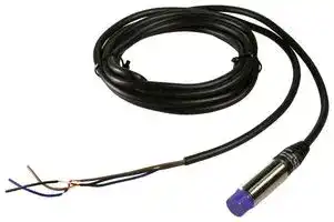
Illustrative purposes only

PRD12-8DP
INDUCTIVE PROXIMITY SENSOR
⚠️ Reference pricing provided. In case of supply shortages, we will connect you with our trusted procurement partners to ensure your project's continuity.
- Manufacturer: AUTONICS
- Product type: Inductive Proximity Sensors
- Product Range: PRD Series
- Sensor Output: PNP
- Sensing Range Max: 8mm
- Thread Size - Metric: M12
- Supply Voltage DC Max: 30V
- Supply Voltage DC Min: 10V
| Delivery and price | |
|---|---|
| Units per pack | 25 |
| Price | 29.53 € |
| Current stock | 10+ |
| Lead time | 30 days |
Datasheet

**PRD/PRDW Series**

**Long Distance Type**

**(A) Photo electric sensorr**

**(B) Fiber optic sensor**

**(C) Door/Area sensor**

**(D) Proximity sensor**

**(E) Pressure sensor (F) Rotary encoder (G) Connector/ Socket**

**(H) Temp. controller (I) SSR/ Power controller (J) Counter (K) Timer (L) Panel meter**

**(M) Tacho/ Speed/ Pulse meter (N) Display unit**

**(O) Sensor controller (P) Switching mode power supply (Q) Stepper motor& Driver&Controller (R) Graphic/ Logic panel (S) Field network device**

**(T) Software (U) Other**

## **Long distance proximity sensor**

## **Features**

- **Long sensing distance**

**==> picture [36 x 9] intentionally omitted <==**

**----- Start of picture text -----**<br>
Line-up<br>**----- End of picture text -----**<br>


- **(1.5 to 2 times longer sensing distance guaranteed compared to existing models)**

- Improved the noise resistance with dedicated IC

- Built-in surge protection, reverse polarity protection, overcurrent protection circuit

- Long life cycle and high reliability

- Red LED status indication

- Protection structure IP67(IEC standard)

- Replaceable for micro switches and limit switches

- Improved cable strain relief : More reliable flexural strength of sensor/cable connecting part

**Please read “Caution for your safety” in operation manual before using.**

## **Specifications**

**● DC 2-wire type PRDT12-4** □ **O PRDT12-8** □ **O PRDT18-7** □ **O PRDT18-14** □ **O PRDT30-15** □ **O PRDT30-25** □ **O PRDT12-4** □ **C PRDT12-8** □ **C PRDT18-7** □ **C PRDT18-14** □ **C PRDT30-15** □ **C PRDT30-25** □ **C PRDT12-4** □ **O-V PRDT12-8** □ **O-V PRDT18-7** □ **O-V PRDT18-14** □ **O-V PRDT30-15** □ **O-V PRDT30-25** □ **O-V PRDT12-4** □ **C-V PRDT12-8** □ **C-V PRDT18-7** □ **C-V PRDT18-14** □ **C-V PRDT30-15** □ **C-V PRDT30-25** □ **C-V PRDLT12-4** □ **O PRDLT12-8** □ **O PRDLT18-7** □ **O PRDLT18-14** □ **O PRDLT30-15** □ **O PRDLT30-25** □ **O PRDLT12-4** □ **C PRDLT12-8** □ **C PRDLT18-7** □ **C PRDLT18-14** □ **C PRDLT30-15** □ **C PRDLT30-25** □ **C PRDLT12-4** □ **O-V PRDLT12-8** □ **O-V PRDLT18-7** □ **O-V PRDLT18-14** □ **O-V PRDLT30-15** □ **O-V PRDLT30-25** □ **O-V PRDLT12-4** □ **C-V PRDLT12-8** □ **C-V PRDLT18-7** □ **C-V PRDLT18-14** □ **C-V PRDLT30-15** □ **C-V PRDLT30-25** □ **C-V** Model **PRDWT12-4** □ **O PRDWT12-8** □ **O PRDWT18-7** □ **O PRDWT18-14** □ **O PRDWT30-15** □ **O PRDWT30-25** □ **O PRDWT12-4** □ **C PRDWT12-8** □ **C PRDWT18-7** □ **C PRDWT18-14** □ **C PRDWT30-15** □ **C PRDWT30-25** □ **C PRDWT12-4** □ **O-I PRDWT12-8** □ **O-I PRDWT18-7** □ **O-I PRDWT18-14** □ **O-I PRDWT30-15** □ **O-I PRDWT30-25** □ **O-I PRDWT12-4** □ **C-I PRDWT12-8** □ **C-I PRDWT18-7** □ **C-I PRDWT18-14** □ **C-I PRDWT30-15** □ **C-I PRDWT30-25** □ **C-I PRDWT12-4** □ **O-IV PRDWT12-8** □ **O-IV PRDWT18-7** □ **O-IV PRDWT18-14** □ **O-IV PRDWT30-15** □ **O-IV PRDWT30-25** □ **O-IV PRDWT12-4** □ **C-IV PRDWT12-8** □ **C-IV PRDWT18-7** □ **C-IV PRDWT18-14** □ **C-IV PRDWT30-15** □ **C-IV PRDWT30-25** □ **C-IV PRDWLT18-7** □ **O-IV PRDWLT18-14** □ **O-IV PRDWLT18-7** □ **C-IV PRDWLT18-14** □ **C-IV** Sensing distance 4mm 8mm 7mm 14mm 15mm 25mm Hysteresis Max. 10% of sensing distance ~~Titty~~ Standard sensing target 12×12×1mm(Iron) 25×25×1mm (Iron) 20×20×1mm (Iron) 40×40×1mm (Iron) 45×45×1mm (Iron) 75×75×1mm (Iron) ~~——~~ Sensing distance 0 to 2.8mm 0 to 5.6mm 0 to 4.9mm ~~Ce~~ 0 to 9.8mm 0 to 10.5mm 0 to 17.5mm Power supply 12-24VDC (Operating voltage) (10-30VDC) ~~$$~~ Leakage current Max. 0.6mA Response frequency[※] **[1]** 450HZ 400Hz 250Hz 200Hz 100Hz Residual voltage[※] **[2]** Max. 3.5V(for non-polarity type, max. 5V) Affection by Temp. Max. ±10% for sensing distance at ambient temperature 20℃ Control output 2 to 100mA Insulation resistance Min. 50MΩ(at 500VDC megger) Dielectric strength 1500VAC 50/60Hz for 1minute Vibration 1mm amplitude at frequency of 10 to 55Hz(for 1 min.) in each of X, Y, Z directions for 2 hours Shock 500m/s²(approx. 50G) X, Y, Z directions for 3 times Indicator Operation indicator(red LED) EnvironAmbient temperature -25 to 70℃, Storage: -30 to 80℃ ~~a~~ ment Ambient humidity 35 to 95%RH, Storage: 35 to 95%RH Protection circuit Surge protection circuit, Reverse polarity protection circuit, Overcurrent protection circuit Material Case/Nut: Nickel plated Brass, Washer: Nickel plated Iron, Sensing surface: Heat-resistant ABS, ~~i~~ Standard cable(Black): Polyvinyl chloride(PVC), Oil resistant cable(Gray): Oil resistant Polyvinyl chloride(PVC) Cable ø4, 2-wire, 2m ø5, 2-wire, 2m (For cable type, 300mm, M12 connector) , (AWG22, Core diameter: 0.08mm, Number of cores: 60, Insulator diameter: ø1.25) ~~———————————~~ Approval Protection IP67(IEC Standard) PRDT: Approx. 74g PRDT: Approx. 72g PRDT: Approx. 115g PRDT: Approx. 110g PRDT: Approx. 175g PRDT: Approx. 180g PRDLT: Approx. 145g PRDLT: Approx. 140g Unit weight PRDLT: Approx. 94g PRDLT: Approx. 92g PRDLT: Approx. 215g PRDLT: Approx. 220g PRDWT: Approx. 80g PRDWT: Approx. 75g PRDWT: Approx. 44g PRDWT: Approx. 42g PRDWLT: Approx. 42g PRDWLT: Approx. 105g PRDWT: Approx. 140g PRDWT: Approx. 145g ※1: The response frequency is the average value. The standard sensing target is used and the width is set as 2 times of  the standard sensing target, 1/2 of the sensing distance for the distance. ※ ~~lft~~ 2: Before using non-polarity type, check the condition of connected device because residual voltage is 5V. ~~tt~~ ※The ' □ ' of model name is for power type. 'D' is 12-24VDC, 'X' is non-polarity 12-24VDC.

- ※The last 'V' of model name is for the model with oil-resistance reinforced cable.

- ※Environment resistance is rated at no freezing or condensation.

D-11

**PRD/PRDW Series**

## **Specifications**

## **● DC 3-wire type**

|Model|Model|**PRD12-4DN**<br>**PRD12-4DP**<br>**PRD12-4DN2**<br>**PRD12-4DP2**<br>**PRDL12-4DN**<br>**PRDL12-4DP**<br>**PRDL12-4DN2**<br>**PRDL12-4DP2**<br>**PRDW12-4DN**<br>**PRDW12-4DP**<br>**PRDW12-4DN2**<br>**PRDW12-4DP2**<br>**PRDW12-4DN-V**<br>**PRDW12-4DP-V**<br>**PRDWL12-4DN**<br>**PRDWL12-4DP**<br>**PRDWL12-4DN2**<br>**PRDWL12-4DP2**|**PRD12-4DN**<br>**PRD12-4DP**<br>**PRD12-4DN2**<br>**PRD12-4DP2**<br>**PRDL12-4DN**<br>**PRDL12-4DP**<br>**PRDL12-4DN2**<br>**PRDL12-4DP2**<br>**PRDW12-4DN**<br>**PRDW12-4DP**<br>**PRDW12-4DN2**<br>**PRDW12-4DP2**<br>**PRDW12-4DN-V**<br>**PRDW12-4DP-V**<br>**PRDWL12-4DN**<br>**PRDWL12-4DP**<br>**PRDWL12-4DN2**<br>**PRDWL12-4DP2**|**PRD12-8DN**<br>**PRD12-8DP**<br>**PRD12-8DN2**<br>**PRD12-8DP2**<br>**PRDL12-8DN**<br>**PRDL12-8DP**<br>**PRDL12-8DN2**<br>**PRDL12-8DP2**<br>**PRDW12-8DN**<br>**PRDW12-8DP**<br>**PRDW12-8DN2**<br>**PRDW12-8DP2**<br>**PRDW12-8DN-V**<br>**PRDW12-8DP-V**<br>**PRDWL12-8DN**<br>**PRDWL12-8DP**<br>**PRDWL12-8DN2**<br>**PRDWL12-8DP2**|**PRD18-7DN**<br>**PRD18-7DP**<br>**PRD18-7DN2**<br>**PRD18-7DP2**<br>**PRDL18-7DN**<br>**PRDL18-7DP**<br>**PRDL18-7DN2**<br>**PRDL18-7DP2**<br>**PRDW18-7DN**<br>**PRDW18-7DP**<br>**PRDW18-7DN2**<br>**PRDW18-7DP2**<br>**PRDW18-7DN-V**<br>**PRDW18-7DP-V**<br>**PRDWL18-7DN**<br>**PRDWL18-7DP**<br>**PRDWL18-7DN2**<br>**PRDWL18-7DP2**|**PRD18-14DN**<br>**PRD18-14DP**<br>**PRD18-14DN2**<br>**PRD18-14DP2**<br>**PRDL18-14DN**<br>**PRDL18-14DP**<br>**PRDL18-14DN2**<br>**PRDL18-14DP2**<br>**PRDW18-14DN**<br>**PRDW18-14DP**<br>**PRDW18-14DN2**<br>**PRDW18-14DP2**<br>**PRDW18-14DN-V**<br>**PRDW18-14DP-V**<br>**PRDWL18-14DN**<br>**PRDWL18-14DP**<br>**PRDWL18-14DN2**<br>**PRDWL18-14DP2**|<br> <br>**PRD30-15DN**<br>**PRD30-15DP**<br>**PRD30-15DN2**<br>**PRD30-15DP2**<br>**PRDL30-15DN**<br>**PRDL30-15DP**<br>**PRDL30-15DN2**<br>**PRDL30-15DP2**<br>**PRDW30-15DN**<br>**PRDW30-15DP**<br>**PRDW30-15DN2**<br>**PRDW30-15DP2**<br>**PRDW30-15DN-V**<br>**PRDW30-15DP-V**<br>**PRDWL30-15DN**<br>**PRDWL30-15DP**<br>**PRDWL30-15DN2**<br>**PRDWL30-15DP2**|**PRD30-25DN**<br>**PRD30-25DP**<br>**PRD30-25DN2**<br>**PRD30-25DP2**<br>**PRDL30-25DN**<br>**PRDL30-25DP**<br>**PRDL30-25DN2**<br>**PRDL30-25DP2**<br>**PRDW30-25DN**<br>**PRDW30-25DP**<br>**PRDW30-25DN2**<br>**PRDW30-25DP2**<br>**PRDW30-25DN-V**<br>**PRDW30-25DP-V**<br>**PRDWL30-25DN**<br>**PRDWL30-25DP**<br>**PRDWL30-25DN2**<br>**PRDWL30-25DP2**|
|---|---|---|---|---|---|---|---|---|
|Sensingdistance||4mm||8mm|7mm|14mm|15mm|25mm|
|Hysteresis||Max. 10% of sensingdistance|||||||
|Standard sensingtarget||12×12×1mm(Iron)||25×25×1mm(Iron)|20×20×1mm(Iron)|40×40×1mm(Iron|)45×45×1mm(Iron)|75×75×1mm(Iron)|
|Sensingdistance||0 to 2.8mm||0 to 5.6mm|0 to 4.9mm|0 to 9.8mm|0 to 10.5mm|0 to 17.5mm|
|Power supply<br>(Operatingvoltage)||12-24VDC<br>(10-30VDC)|||||||
|Current consumption||Max. 10mA|||||||
|Response frequency※**1**||500Hz||400Hz|300Hz|200Hz|100HZ|100Hz|
|Residual voltage||Max. 1.5V|||||||
|Affection byTemp.||Max.±10% for sensingdistance at ambient temperature 20℃|||||||
|Control output||200mA|||||||
|Insulation resistance||Min. 50MΩ(at 500VDC megger)|||||||
|Dielectric strength||1500VAC 50/60Hz for 1minute|||||||
|Vibration||1mm amplitude at frequencyof 10 to 55Hz(for 1 min.)in each of X, Y, Z directions for 2 hours|||||||
|Shock||500m/s²(approx. 50G)X, Y, Z directions for 3 times|||||||
|Indicator||Operation indicator(red LED)|||||||
|Environ-<br>ment|Ambient temperature|-25 to 70℃, Storage: -30 to 80℃|||||||
||Ambient humidity|35 to 95%RH, Storage: 35 to 95%RH|||||||
|Protection circuit||Surgeprotection circuit, Reversepolarity protection circuit, Overcurrentprotection circuit|||||||
|Protection||IP67(IEC Standard)|||||||
|Material||Case/Nut: Nickel plated Brass, Washer: Nickel plated Iron, Sensing surface: Heat-resistant ABS,<br>Standard cable(Black): Polyvinyl chloride(PVC), Oil resistant cable(Gray): Oil resistant Polyvinyl chloride(PVC)|||||||
|Cable||ø4, 3-wire, 2m|||ø5, 3-wire, 2m||||
|||(For cable type, 300mm, M12 connector),(AWG22, Core diameter: 0.08mm, Number of cores: 60, Insulator diameter: ø1.25)|||||||
|Approval|||||||||
|Unit weight||PRD:Approx. 74g<br>PRDL:Approx. 94g<br>PRDW:Approx. 44g<br>PRDWL:Approx. 64g||PRD:Approx. 72g<br>PRDL:Approx. 92g<br>PRDW:Approx. 42g<br>PRDWL:Approx. 62g|PRD:Approx. 115g<br>PRDL:Approx. 145g<br>PRDW:Approx. 80g<br>PRDWL:Approx. 110g|PRD:Approx. 110g<br>PRDL:Approx. 140g<br>PRDW:Approx. 75g<br>PRDWL:Approx. 105g|PRD:Approx. 175g<br>PRDL:Approx. 215g<br>PRDW:Approx. 140g<br>PRDWL:Approx. 180g|PRD:Approx. 180g<br>PRDL:Approx. 220g<br>PRDW:Approx. 145g<br>PRDWL:Approx. 185g|


- ※1: The response frequency is the average value. The standard sensing target is used and the width is set as 2 times of the standard sensing target, 1/2 of the sensing distance for the distance.

※The last 'V' of model name is for the model with oil-resistance reinforced cable.

※Environment resistance is rated at no freezing or condensation.

## **Dimensions**

**==> picture [436 x 114] intentionally omitted <==**

**----- Start of picture text -----**<br>
 Dimensions<br>(unit: mm)<br>● PRD(T)12-4D ● PRD(T)12-8D<br>ø21 52 2000 ø21 52 2000<br>17 31.5 17 7 24.5<br>ø4 ø4<br>4 Operation  4 Operation<br>indicator indicator<br>M12X1 M12X1<br>**----- End of picture text -----**<br>


D-12

**Long Distance Type**

**==> picture [481 x 623] intentionally omitted <==**

**----- Start of picture text -----**<br>
 Dimensions  (unit: mm) (A) Photo<br>electric<br>● PRDL(T)12-4D ● PRDL(T)12-8D sensorr<br>ø21 64 2000 ø21 64 2000 (B)<br>17 44 17 7 37 Fiberoptic<br>sensor<br>(C)<br>Door/Area<br>ø4 ø4 sensor<br>4 M12×1Operation indicator 4 M12×1Operation indicator (D) Proximity<br>● PRD(T)18-7D ● PRD(T)18-14D sensor<br>ø29 53 2000 ø29 53 2000 (E)<br>Pressure<br>24 29.5 24 10 19 sensor<br>(F)<br>Rotary<br>encoder<br>ø5 ø5<br>Operation indicator Operation indicator (G)<br>4 M18×1 4 M18×1 Connector/Socket<br>● PRDL(T)18-7D ● PRDL(T)18-14D (H)<br>ø29 86 2000 ø29 86 2000 Temp.controller<br>24 62 24 10 52<br>(I)<br>SSR/<br>Power<br>controller<br>ø5 ø5 (J)<br>4 M18×1Operation  indicator 4 M18×1Operation  indicator Counter<br>(K)<br>● PRD(T)30-15D ● PRD(T)30-25D Timer<br>ø42 62 2000 ø42 62 2000<br>35 38 35 10 28 (L) Panel<br>meter<br>(M)<br>Tacho/<br>Speed/ Pulse<br>meter<br>ø5 ø5<br>Operation indicator Operation indicator (N)Display<br>5 M30×1.5 5 M30×1.5 unit<br>● PRDL(T)30-15D ● PRDL(T)30-25D (O)Sensor<br>ø42 84 2000 ø42 84 2000 controller<br>35 60 35 10 50 (P)<br>Switching<br>mode power<br>supply<br>(Q)<br>Stepper<br>motor&<br>Driver&Controller<br>ø5 ø5<br>Operation  Operation   (R)<br>5 M30×1.5 indicator 5 M30×1.5 indicator Graphic/Logic<br>panel<br>● PRDW(T)12-4D (S)<br>ø21 52 300 Field<br>17 31.5 networkdevice<br>(T)<br>Software<br>4 Operation indicator ø4<br>M12×1 M12 (U)<br>● PRDW(T)12-8D Other<br>ø21 52 300<br>17 7 24.5<br>4 Operation indicator ø4<br>M12×1 M12<br>**----- End of picture text -----**<br>


D-13

## **PRD/PRDW Series**

## **Dimensions**

(unit: mm)

**==> picture [436 x 610] intentionally omitted <==**

**----- Start of picture text -----**<br>
● PRDWL12-4D ø21 64 300<br>17 44<br>Operation indicator ø4<br>● PRDWL12-8D 4 M12×1 M12<br>ø21 64 300<br>17 7 37<br>Operation indicator ø4<br>4 M12×1 M12<br>● PRDW(T)18-7D ø29 62 300<br>24 38.5<br>Operation indicator ø5<br>4 M18×1 M12<br>● PRDW(T)18-14D ø29 62 300<br>24 10 29<br>Operation indicator ø5<br>4 M18×1 M12<br>● PRDWL(T)18-7D ø29 86 300<br>24 62<br>Operation indicator ø5<br>4 M18×1 M12<br>● PRDWL(T)18-14D ø29 86 300<br>24 10 52<br>Operation indicator ø5<br>4 M18×1 M12<br>● PRDW(T)30-15D<br>ø42 62 300<br>35 38<br>Operation indicator ø5<br>M12<br>5 M30×1.5<br>● PRDW(T)30-25D<br>ø42 62 300<br>35 10 28<br>Operation indicator ø5<br>M12<br>5 M30×1.5<br>**----- End of picture text -----**<br>


D-14

**(A) Photo electric sensorr (B) Fiber optic sensor**

**(C) Door/Area sensor**

**(D) Proximity sensor**

**(E) Pressure sensor (F) Rotary encoder (G) Connector/ Socket (H) Temp. controller (I)SSR/ SSR/ Power controller (J) Counter Counter (K) Timer Timer (L) Panelmeter Panelmeter meter**

## **Long Distance Type**

## **Dimensions**

**==> picture [33 x 8] intentionally omitted <==**

**----- Start of picture text -----**<br>
(unit: mm)<br>**----- End of picture text -----**<br>


**==> picture [390 x 179] intentionally omitted <==**

**----- Start of picture text -----**<br>
● PRDWL(T)30-15D<br>ø42 84 300<br>35 60<br>Operation indicator ø5<br>M12<br>5 M30×1.5<br>● PRDWL(T)30-25D<br>ø42 84 300<br>35 10 50<br>Operation indicator ø5<br>M12<br>5 M30×1.5<br>**----- End of picture text -----**<br>


## **Control output diagram DC 2-wire type**

**==> picture [481 x 408] intentionally omitted <==**

**----- Start of picture text -----**<br>
 DC 2-wire type  DC 3-wire type (I)SSR/<br>Power<br>Brown NPN output type controller<br>4 Load +V Sensingtarget PresenceNothing N.O. N.C. 1 Brown +V Sensingtarget PresenceNone N.O. N.C. (J) Counter<br>Load OperationReturn 10㏀ 4 BlackLoad Output voltage(brown-black)Load HOperationReturn (K) Timer<br>3Blue 0V Operation(red LED)Indicator ONOFF 3 Blue 0V (black-blue)Operation(red LED)Indicator LONOFF (L) Panelmeter<br>※The number in a circle is pin no. of connector. PNP output type (M)Tacho/<br>1 Brown +V Sensing Presence N.O. N.C. Speed/ Pulsemeter<br>target None<br>4 Black (black-blue)Load OperationReturn (N)Displayunit<br>10㏀ Load Output voltage(black-blue) HL (O)<br>Sensor<br>3 Blue 0V Operation(red LED)Indicator ONOFF controller<br>(P)<br>Switching<br>mode power<br>Connections supply<br>(Q)<br> DC 2-wire type Brown Load +V Steppermotor&Driver&Controller<br>※The load can be connected to either wire. (R)Graphic/<br>Logic<br>Blue panel<br>Load 0V<br>(S)<br>Field<br> DC 3-wire type Brown Blue Black networkdevice<br>Black Brown Blue (T) Software<br>8 9 10 11 12 1314<br>(PRD18-7DN) cp1 cp2 +12V 0V<br>(U)<br>(PRD18-7DN) Other<br>1 2 3 4 5 6 7<br>(PRD18-7DN)<br>< FX4 > 100-240VAC<br>< PA10-U ><br>Main circuit<br>Main circuit<br>Main circuit<br>Black Blue Brown<br>**----- End of picture text -----**<br>


D-15

## **PRD/PRDW Series**

## **Wiring diagram**

## **DC 2-wire type(Standard type)**

**==> picture [210 x 56] intentionally omitted <==**

**----- Start of picture text -----**<br>
Normally Open(N.O.) / Normally Closed(N.C.)<br>2 1 Brown 2 1<br>Brown<br>3 4 Load +V 3 4 +V<br>Blue 0V Blue Load 0V<br>**----- End of picture text -----**<br>


- ※Pin ①, ② are not used terminals.

- ※For DC 3-wire type connector cable, it is available to use with black wire(12-24VDC) and blue wire(0V).

## **DC 2-wire type(IEC standard type)**

**==> picture [210 x 70] intentionally omitted <==**

**----- Start of picture text -----**<br>
Normally Open(N.O.) Normally Closed(N.C.)<br>Brown Brown<br>2 1 Load +V 2 1 Load +V<br>3 4 3 4<br>Blue Blue<br>0V 0V<br>**----- End of picture text -----**<br>


## **DC 3-wire type**

**==> picture [211 x 65] intentionally omitted <==**

**----- Start of picture text -----**<br>
NPN output type PNP output type<br>Brown Brown<br>2 1 +V 2 1 +V<br>Black<br>3 4 Load 3 4<br>Black Load<br>Blue 0V Blue 0V<br>**----- End of picture text -----**<br>


- ※Please fasten the cleat of connector not to shown the thread.

- (0.39 to 0.49N[.] m)

- ※Please fasten the vibration part with Teflon tape.

- ※Refer to the G-6 about IEC standard connector wires and specifications.

※②,③ of N.O. type and ③,④ of N.C. type are not used terminals.

※The pin arrangement of connector applying IEC standard is being developed.

- ※Please attach "I" at the end of the name of standard type for purchasing the IEC standard product.  Ex)PRDWT12-4DO-I

※The connector cable for IEC standard is being developed. Please attach "I' at the end of the name of standard type. Ex)CID2-2-I, CLD2-5-I

## **Proper usage**

## **Load connections**

**==> picture [270 x 59] intentionally omitted <==**

**----- Start of picture text -----**<br>
Brown Brown<br>Load<br>+ + 24VDC<br>- -<br>Blue Blue<br>Load<br>< DC 2-wire type > < DC 2-wire type ><br>**----- End of picture text -----**<br>


Please make the current on proximity sensor smaller than the return current of load by connecting a bleeder resistor in parallel.

## **In case of the load current is small**

## **● DC 2-wire type**

Brown Load ※W value of Bleeder resistor should be bigger for proper Bleeder resistor(R) +- Vs heat dissipation.R = Io-Ioff (Ω)     Vs P =  R  (W)     Vs2 Blue [ Vs  : Power supply,Ioff : Return current of load, Io : Min. action current of proximity sensorP : Number of Bleeder resistance watt ]

## **Mutual-interference**

|When several proximity sensors are mounted close to one<br>another a malfunction of the sensor may be caused due<br>to mutual interference. Therefore, be sure to provide a<br>minimum distance between the two sensors as below chart<br>indicates.<br>When sensors are mounted on metallic panel, you must<br>prevent the sensors from being affected by any metallic<br>object except target. Therefore, be sure to provide a<br>minimum distance as below chart indicates.<br> <br>**Influence by surrounding metals**|When several proximity sensors are mounted close to one<br>another a malfunction of the sensor may be caused due<br>to mutual interference. Therefore, be sure to provide a<br>minimum distance between the two sensors as below chart<br>indicates.<br>When sensors are mounted on metallic panel, you must<br>prevent the sensors from being affected by any metallic<br>object except target. Therefore, be sure to provide a<br>minimum distance as below chart indicates.<br> <br>**Influence by surrounding metals**|When several proximity sensors are mounted close to one<br>another a malfunction of the sensor may be caused due<br>to mutual interference. Therefore, be sure to provide a<br>minimum distance between the two sensors as below chart<br>indicates.<br>When sensors are mounted on metallic panel, you must<br>prevent the sensors from being affected by any metallic<br>object except target. Therefore, be sure to provide a<br>minimum distance as below chart indicates.<br> <br>**Influence by surrounding metals**|When several proximity sensors are mounted close to one<br>another a malfunction of the sensor may be caused due<br>to mutual interference. Therefore, be sure to provide a<br>minimum distance between the two sensors as below chart<br>indicates.<br>When sensors are mounted on metallic panel, you must<br>prevent the sensors from being affected by any metallic<br>object except target. Therefore, be sure to provide a<br>minimum distance as below chart indicates.<br> <br>**Influence by surrounding metals**|||||||Parallel<br>B|Parallel<br>B|Parallel<br>B|Parallel<br>B|||
|---|---|---|---|---|---|---|---|---|---|---|---|---|---|---|---|
|||||||Face to Face<br>A||||||||||
|||||||||||||||m<br>ℓ|n|
|||||||||||ℓ|ød|||||
|||||||ℓ||||||||(unit: mm)||
|Mode<br>Item|l<br>PRDT12-4□□<br>PRDWT12-4□□<br>PRDLT12-4□□|PRDT12-8□□<br>PRDWT12-8□□<br>PRDLT12-8□□<br><br><br><br>|PRDT18-7□□<br>PRDWT18-7□□<br>PRDLT18-7□□<br>PRDWLT18-7□□|PRDT18-14□□<br>PRDWT18-14□□<br>PRDLT18-14□□<br>PRDWLT18-14□□||||PRDT30-15□□<br>PRDWT30-15□□<br>PRDLT30-15□□||||P<br>P<br>P|RDT30-25□□<br>RDWT30-25□□<br>RDLT30-25□□|||
|A|24|48<br>|42|84||||90||||1|50|||
|B|24|36<br>|36|54||||60||||9|0|||
|ℓ|0|11<br>|0|14||||0||||1|5|||
|ød|12|36<br>|18|54||||30||||9|0|||
|m|12|24<br>|21|42||||45||||7|5|||
|n|18|36<br>|27|54||||45||||9|0|||


D-16
Updated at February 9, 2023
About Novapart
Novapart is a B2B electronic component broker specialising in stock shortages and cost reduction. We source hard-to-find parts and identify compliant alternatives across a catalogue of 410,000+ components from 500+ manufacturers.
Learn more →Stock Shortage Specialist
When a component is unavailable, discontinued or has an unacceptable lead time, we tap into our network of vetted European and Asian distributors to source what you need — without compromising on quality or traceability.
Request a quote →Compliant Alternatives
We identify pin-to-pin, electrically equivalent substitutes that meet the same certifications (RoHS, AEC-Q100, REACH) as your original specification — validated against datasheets, not just part numbers. Often at a lower cost.
BOM Analysis service →