
Image not available
Illustrative purposes only

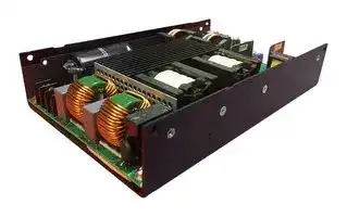
PQU1000-48
AC/DC Open Frame Power Supply (PSU), ITE & Medical, 1 Output, 1kW, 800 W, 90V AC to 264V AC
⚠️ Reference pricing provided. In case of supply shortages, we will connect you with our trusted procurement partners to ensure your project's continuity.
- Manufacturer: MURATA POWER SOLUTIONS
- Product type: AC / DC Open Frame Power Supplies
- SVHC: No SVHC (04-Feb-2026)
- Product Range: PQU1000 Series
- No. of Outputs: 1 Output
- Input Voltage VAC: 90V AC to 264V AC
- Power Supply Output Type: Adjustable, Fixed
- Output Current - Output 1: 20.8A
- Output Current - Output 2: -
- Output Current - Output 3: -
- Output Current - Output 4: -
- Output Voltage - Output 1: 48VDC
- Output Voltage - Output 2: -
- Output Voltage - Output 3: -
- Output Voltage - Output 4: -
- Power Supply Applications: ITE & Medical
- Power Rating (Forced Cooling): 1kW
- Power Rating (Convection Cooling): 800W
| Delivery and price | |
|---|---|
| Units per pack | 5 |
| Price | 229.82 € |
| Current stock | 10+ |
| Lead time | 30 days |
Datasheet

PQU1000 Series

## | muRata | Ps! Murata Power Solu ~~t~~ ions

1000W 5" x 8" AC-DC “U” Channel Power Supply Converter

## FEATURES

- Compact high-density design with operation:

   - Up to 800W[4 ] natural convection

   - 1000W with forced convection airflow at +50°C; no derating with input line voltage

- Optional cover kits available, with or without fan

- Voltage adjustment (-5%; +10%)[2] of Main V1 Output

- +5VAux/Standby (V2) and 12V (V3) Fan outputs

- 5" x 8" (127mm x 203.2mm) industry standard footprint; “U” channel form factor with industry “standard” mounting footprints

   - 39.97mm maximum overall “U” Channel height

   - 45.60mm nominal overall height with cover

   - 67.93mm nominal overall height with integral fan cover

- High effciency of 95% typical at 50% load

- True zero load operation of the Main (V1) output; no minimum load requirements[3]

- Remote sense for the main output

- Universal AC input; active PFC; EN61000-3-2 Class A

- MTBF 1135Khrs; Telcordia SR332 Issue 3; M1 Case 3

- RoHS compliant

- Active inrush protection

**==> picture [224 x 13] intentionally omitted <==**

**----- Start of picture text -----**<br>
Shown with optional cover kit  Shown with optional cover kit<br>PQU1000-FT-COVER installed  PQU1000--COVER installed<br>**----- End of picture text -----**<br>


- Active Current Share

- IEC60601 Ed.3 medical (2 x MOPP Pri-Sec)

- Applied Part BF rating (isolation and patient leakage currents)

- 1 x MOPP Pri-Chassis Ground)

- IEC62368-1

- Designed to comply with IEC60601-2 4[th] Edition EMC Standard Requirements[1]

   - 1 End User Systems verification shall be required

   - 2 54V output adjustment range is ±5% max to maintain max voltage to <60V to maintain SELV limits

   - 3 Zero load output voltage may exceed the regulation window

   - 4 See derating curves

## DESCRIPTION

PQU1000 is a series of 1000W power supply converters, powered by wide range AC input, and offered in a compact 5" x 8" industry standard format. 1000W[1] continuous output power can be achieved with forced convection, and up to an impressive 800W[3] , at +50°C with natural convection airflow. All variants are provided with constant current overload protection allowing operation with motors, solenoids, and high capacitance loads. Active current sharing supports connection of PQU1000 power modules in either non-redundant parallel, or parallel redundant deployments, whilst maintaining equal current share between modules.

The adjustable main output, standby/auxiliary, and fan outputs, plus PMBus[TM] Power Management Bus enable this series for deployment across multiple market sectors, complemented by safety certification applicable to medical, audio, video, communication and ITE standards.

|ORDERING GUIDE (MODEL NUMBER)<br>~~a~~|ORDERING GUIDE (MODEL NUMBER)<br>~~a~~|ORDERING GUIDE (MODEL NUMBER)<br>~~a~~|ORDERING GUIDE (MODEL NUMBER)<br>~~a~~|ORDERING GUIDE (MODEL NUMBER)<br>~~a~~|ORDERING GUIDE (MODEL NUMBER)<br>~~a~~|ORDERING GUIDE (MODEL NUMBER)<br>~~a~~|
|---|---|---|---|---|---|---|
|Model (Order) Number<br>~~a~~|Main output (V1)<br>~~a~~||Aux Output (V2)<br>~~a~~||Fan Output (V3)4<br>~~a~~||
||Voltage (Vdc)|Current Adc; @ 50°C; 1000W1|Vdc|Current (Adc @ 50°C)|Vdc|Current (Adc @ 50°C)|
|PQU1000-12|12|83.3|5|1.0|12|1.0|
|PQU1000-24|24|41.7|||||
|PQU1000-482|48|20.8|||||
|PQU1000-542|54|18.5|||||
|PQU1000-COVER3|Optional cover kits (End-User assembly required)||||||
|PQU1000-FT-COVER5|||||||


- 1 Require external system airflow or PQU1000-FT-COVER with integral fan

- 2 PoE Isolation Compliant

   - 4 Only available for forced air cooled deployments (not rated for convection cooled (deployments). 5 Cover assembly with integral top mounted fan

- 3 Some minor derating required

- https://www.murata ps.com/support

PQU1000.A02.D01  Page 1 of 15

PQU1000 Series

## | muRata | Ps! Murata Power Solu ~~t~~ ions

1000W 5" x 8" AC-DC “U” Channel Power Supply Converter

|**INPUT CHARACTERISTICS**<br>~~hii~~|**INPUT CHARACTERISTICS**<br>~~hii~~|**INPUT CHARACTERISTICS**<br>~~hii~~|**INPUT CHARACTERISTICS**<br>~~hii~~|**INPUT CHARACTERISTICS**<br>~~hii~~|**INPUT CHARACTERISTICS**<br>~~hii~~|
|---|---|---|---|---|---|
|Parameter<br>~~hii~~<br>~~|~~|Conditions<br>~~hii~~<br>~~|~~|Min<br>~~hii~~|Nom<br>~~hii~~|Max<br>~~hii~~<br>~~|~~|Units<br>~~hii~~<br>~~|~~|
|Input Voltage AC Operating Range<br>~~|~~|Single Phase<br>~~|~~|901|100/240|264<br>~~|~~|VAC<br>~~|~~|
|Input Frequency||47|50/60|63|Hz|
|Turn-on input voltage|Input rising|751||90|Vac|
|Turn-off input voltage|Input falling|65||80|Vac|
|Maximum input current (target)|Vin = 90Vac; Full Load<br>(1000W FL)|||13|Arms|
|Inrush Current|230VAC,Cold start, 25°C;|||50|Apk|
|Power Factor|At 115VAC/230VAC, full load|0.95|||W/VA|
|Hold-up Time (Target)|90VAC; Full Load|10|||ms|
|Target Efficiency @ 230Vac|20% Full Load||92||%|
||50% Full Load||95|||
||100% Full Load||95|||


1Operation at 80Vac is possible at 650W and +50°C; however, the specification is not guaranteed at an input voltage of less than 90VAC

|MAIN OUTPUT CHARACTERISTICS (ALL MODELS)<br>~~a~~<br>~~aaaaaaaaaaaaaeaeaeaeaeaeaeaeaeaoavaulwl~~|MAIN OUTPUT CHARACTERISTICS (ALL MODELS)<br>~~a~~<br>~~aaaaaaaaaaaaaeaeaeaeaeaeaeaeaeaoavaulwl~~|MAIN OUTPUT CHARACTERISTICS (ALL MODELS)<br>~~a~~<br>~~aaaaaaaaaaaaaeaeaeaeaeaeaeaeaeaoavaulwl~~|MAIN OUTPUT CHARACTERISTICS (ALL MODELS)<br>~~a~~<br>~~aaaaaaaaaaaaaeaeaeaeaeaeaeaeaeaoavaulwl~~|MAIN OUTPUT CHARACTERISTICS (ALL MODELS)<br>~~a~~<br>~~aaaaaaaaaaaaaeaeaeaeaeaeaeaeaeaoavaulwl~~|MAIN OUTPUT CHARACTERISTICS (ALL MODELS)<br>~~a~~<br>~~aaaaaaaaaaaaaeaeaeaeaeaeaeaeaeaoavaulwl~~|
|---|---|---|---|---|---|
|Parameter<br>~~a~~<br>~~aaaaaaaaaaaaaeaeaeaeaeaeaeaeaeaoavaulwl~~|Conditions<br>~~aaaaaaaaaaaaaeaeaeaeaeaeaeaeaeaoavaulwl~~|Min<br>~~aaaaaaaaaaaaaeaeaeaeaeaeaeaeaeaoavaulwl~~|Nom<br>~~aaaaaaaaaaaaaeaeaeaeaeaeaeaeaeaoavaulwl~~|Max<br>~~aaaaaaaaaaaaaeaeaeaeaeaeaeaeaeaoavaulwl~~|Units<br>~~aaaaaaaaaaaaaeaeaeaeaeaeaeaeaeaoavaulwl~~|
|Line, Load Regulation|Main (V1) Output1|||±5|%|
|Minimum Load Capability|Stable Operation|0|||A|
|Output Ripple|Zero to Full Load2|||1%|mVPP|
|Transient Response3|50% load step, 1A/µsec slew rate and min 10% load i.e. 10% to<br>60%; 100% to 50%|||± 5|%|
|SettlingTime to 1% of Nominal||||2|msec|
|Turn On Delay|After application of inputpower|||3|sec|
|Output Voltage Rise|||200||msec|
|Remote Sense4|Compensates for up to 500mV of total lead drop (output and<br>return connections) with remote sense connected. Protected<br>against short circuit and reverse connection.|||1|%|


- 1  Zero load output voltage may exceed the regulation window however will not cause OVP to engage or PWOK to change to low state

2  Ripple and noise are measured with 0.1uF ceramic capacitor and 10uF tantalum capacitor. A short coaxial cable with 50-ohm termination is used. Min 120uF cap required at the output to keep ripple within 1% for 54V output. Min 10% load current required, to maintain ripple within 1% for the 12V output model

1A min load for all other models

3  Minimum of 1 second time between consecutive transients; requires 10% minimum load

4  If remote sense is left unterminated (floating) then the output voltage set point will increase by 500mVdc

|AUXILIARY OUTPUT CHARACTERISTICS<br>~~SS)~~|AUXILIARY OUTPUT CHARACTERISTICS<br>~~SS)~~|AUXILIARY OUTPUT CHARACTERISTICS<br>~~SS)~~|AUXILIARY OUTPUT CHARACTERISTICS<br>~~SS)~~|AUXILIARY OUTPUT CHARACTERISTICS<br>~~SS)~~|AUXILIARY OUTPUT CHARACTERISTICS<br>~~SS)~~|
|---|---|---|---|---|---|
|Auxiliary Output|Aux Output<br>Voltage|Load Current|Load Capacitance|Line, Load, Cross<br>Regulation|Ripple Voltage &<br>Noise|
|Aux(V2)|5V|0 to 0.5A|0 to 220µF|4.75 to 5.25Vdc|100mVPP|
|||||||
|FAN OUTPUT CHARACTERISTICS(ALL MODELS)<br>~~eee~~||||||
|Auxiliary Output1,2|Aux Output<br>Voltage|Load Current|Load Capacitance|Line, Load, Cross<br>Regulation|Ripple Voltage &<br>Noise|
|Aux(V3)|12V|0 to 0.6A|0 to 220µF|10.8 to 13.2Vdc|120mVPP|


1 Not recommended for “general use” due to its semi regulated characteristic. The output is for use with a fan intended to cool the PQU650M; therefore, if the PQU650M is convection cooled only then this output should not be used. A 1.5A non-replaceable fuse is provided in this output for overload protection

2 Only available for forced convection cooled deployments (not available for natural convection cooled deployments)

## ~~E::::::—————————~~ MAIN OUTPUT CHARACTERISTICS (ALL MODELS UNLESS OTHERWISE NOTED)

|MAIN OUTPUT CHARACTERISTICS (ALL MODELS UNLESS OTHERWISE NOTED)<br>~~E::::::—————————~~<br>~~eee~~|MAIN OUTPUT CHARACTERISTICS (ALL MODELS UNLESS OTHERWISE NOTED)<br>~~E::::::—————————~~<br>~~eee~~|MAIN OUTPUT CHARACTERISTICS (ALL MODELS UNLESS OTHERWISE NOTED)<br>~~E::::::—————————~~<br>~~eee~~|MAIN OUTPUT CHARACTERISTICS (ALL MODELS UNLESS OTHERWISE NOTED)<br>~~E::::::—————————~~<br>~~eee~~|MAIN OUTPUT CHARACTERISTICS (ALL MODELS UNLESS OTHERWISE NOTED)<br>~~E::::::—————————~~<br>~~eee~~|
|---|---|---|---|---|
|Parameter<br>Conditions<br>~~E::::::—————————~~|Conditions<br>~~E::::::—————————~~<br>~~eee~~|Typ.<br>~~eee~~|Max.<br>~~eee~~|Units<br>~~eee~~|
|Transient Response1<br>50% load step, 1A/µsec slew rate and min 10% load i.e. 10% to 60%; 100% to 50%|50% load step, 1A/µsec slew rate and min 10% load i.e. 10% to 60%; 100% to 50%||± 5|%|
|SettlingTime to 1% of Nominal|||2|msec|
|Turn On Delay<br>After a|After application of inputpower||3|sec|
|Output Voltage Rise||200||msec|
|Remote Sense2<br>Compensates for up to 500mV of total lead drop (output and return connections) with<br>remote sense connected. Protected against short circuit and reverse connection.|Compensates for up to 500mV of total lead drop (output and return connections) with<br>remote sense connected. Protected against short circuit and reverse connection.||1|%|
|1Minimum of 1 second time between consecutive transients; requires 10% minimum load<br>2If remote sense is left unterminated (floating) then the output voltage set point will increase by 500mVdc|||||


- https://www.murata ps.com/support

PQU1000.A02.D01  Page 2 of 15

PQU1000 Series

1000W 5" x 8" AC-DC “U” Channel Power Supply Converter

## | muRata | Ps! Murata Power Solu ~~t~~ ions

## ~~E::::::—————————~~ ENVIRONMENTAL CHARACTERISTICS

|ENVIRONMENTAL CHARACTERISTICS<br>~~E::::::—————————~~<br>~~eee~~|ENVIRONMENTAL CHARACTERISTICS<br>~~E::::::—————————~~<br>~~eee~~|ENVIRONMENTAL CHARACTERISTICS<br>~~E::::::—————————~~<br>~~eee~~|ENVIRONMENTAL CHARACTERISTICS<br>~~E::::::—————————~~<br>~~eee~~|ENVIRONMENTAL CHARACTERISTICS<br>~~E::::::—————————~~<br>~~eee~~|ENVIRONMENTAL CHARACTERISTICS<br>~~E::::::—————————~~<br>~~eee~~|
|---|---|---|---|---|---|
|Parameter<br>~~E::::::—————————~~|Conditions<br>~~E::::::—————————~~|Min.|Typ.<br>~~eee~~|Max.<br>~~eee~~|Units<br>~~eee~~|
|Storage Temperature Range||-40||85|°C|
|OperatingTemperature Range2|Seepowerderatingcurves|-30||70||
|OperatingHumidity|Non-condensing|10||95|%|
|OperatingAltitude||0||50001|m|
|MTBF|Telcordia SR-332 Issue 3; M1C3 @ 25°C<br>Telcordia SR-332 Issue 3; M1C3 @ 40°C||2140K<br>1135K||Hours|
|Shock|30G, non-operating; Validation testing per IEC 60068-2-27, test Ea.<br>30G, 11msec half-sine, 3 shocks per face, 6 faces.|Complies||||
|Operational Vibration|Sine Sweep; 5-150Hz, 2G<br>Random Vibration, 5-500Hz, 1.11G|Complies||||
|Safety – Medical Standards1<br>2 x MOPP (Primary-Secondary)<br>Applied Part Type BF|IEC 60601-1:2005/AMD1:2012 [TÜV SÜD]<br>CAN/CSA-C22.2 No. 60601-1:2014 [TÜV SÜD]<br>ANSI/AAMI ES60601-1:2005/A1:2012-08  [TÜV SÜD]<br>EN 60601-1:2006/A1:2013  [TÜV SÜD]|||||
|Safety – ITE,<br>Audio/Video/Communications &<br>Consumer Standards1|IEC 62368-1:2014 [CSA]<br>CAN/CSA-C22.2 No. 62368-1:14[CSA]<br>UL 62368-1 2nd Ed. [CSA]<br>GB 17625.1-2012; GB 4943.1-2011; GB/T 9254-2008 (Class A) [CCC]<br>EN IEC 62368-1:2020/A11:2020 [TÜV SÜD]<br>CE [Self-Declaration]<br>UKCA [Self-Declaration]|||||
|Fuses (Input)|Dual Fuses; Line and Neutral; 16A Fast Acting; 250V|||||
|Outside Dimensions (“U”Channel only).|5.0"x 8.0"x 1.69"(127.0mm x 203.2mm x 40.0mm) nominal|||||
|Weight (typ.)|1.18/2.60||||kg/lbs.|
|1Meets 5000 M max. altitude for Medical certification requirements<br>2Starts up at-40°C; however full specification guaranteed at-30°C||||||


|ISOLATION CHARACTERISTICS<br>~~E::::::—————————~~<br>~~eee~~|ISOLATION CHARACTERISTICS<br>~~E::::::—————————~~<br>~~eee~~|ISOLATION CHARACTERISTICS<br>~~E::::::—————————~~<br>~~eee~~|ISOLATION CHARACTERISTICS<br>~~E::::::—————————~~<br>~~eee~~|ISOLATION CHARACTERISTICS<br>~~E::::::—————————~~<br>~~eee~~|ISOLATION CHARACTERISTICS<br>~~E::::::—————————~~<br>~~eee~~|
|---|---|---|---|---|---|
|Parameter<br>~~E::::::—————————~~|Conditions<br>~~E::::::—————————~~|Min.<br>~~eee~~|Typ.<br>~~eee~~|Max.<br>~~eee~~|Units<br>~~eee~~|
|Isolation|Primaryto Chassis|1500|||Vac2|
||Primaryto Secondary (2xMOPP)|4800||||
||Secondaryto Chassis1|1500||||
||Main Output to other outputs1|1500||||
|Touch Currents(IEC62368-1)|264Vac,60Hz,25°C|||1.5|mApk|
|Patient Leakage Current (under normal conditions)|Meets relevant max Type B and BF patient<br>leakage current limits|||100|µA|


- 1 Meets PoE isolation limits

2 Isolation is verified during safety compliance testing by the use of an equivalent DC voltage as defined by IEC60601-1 3rd Edition; Section 8.8.3 using values as per Table 6, based upon the relevant peak working voltage

|PROTECTION CHARACTERISTICS<br>~~nn~~|PROTECTION CHARACTERISTICS<br>~~nn~~|PROTECTION CHARACTERISTICS<br>~~nn~~|PROTECTION CHARACTERISTICS<br>~~nn~~|PROTECTION CHARACTERISTICS<br>~~nn~~|PROTECTION CHARACTERISTICS<br>~~nn~~|PROTECTION CHARACTERISTICS<br>~~nn~~|
|---|---|---|---|---|---|---|
|Parameter<br>~~nn~~||Conditions<br>~~nn~~|Min.<br>~~nn~~|Typ.<br>~~nn~~|Max.<br>~~nn~~|Units<br>~~nn~~|
|Over Voltage Protection||V1 (main output) latching|110||140|%Vdc2|
|||V1 (48V & 54V models)<br>latching|||60|Vdc|
|||V2 (aux output) latching|5.5||7.5||
|Over Current Protection||V1, See Constant Current<br>curves below|||||
|||V2,cycling,auto-recovery|110||150|%|
|||V3;non-resettable fuse1|||1.5|Adc|
|Over Temperature Protection|Primary Heatsink Temperature||||130|°C|
||Secondary  Temperature||||130||
|Remote Sense Short Circuit Protection||||Complies||--|
|Remote Sense Reverse Connection Protection||||Complies||--|


1 OCP of the 12V Fan (V3) output is provided by a non-user replaceable SMD fuse rated at 1.5A; therefore, if ruptured the 12V Fan output will not be available and the fuse shall require to be replaced

2 Refers to percentage of nominal voltage

- https://www.murata ps.com/support

PQU1000.A02.D01  Page 3 of 15

PQU1000 Series

## muRata Murata Power Solulut ~~ti~~ ions

1000W 5" x 8" AC-DC “U” Channel Power Supply Converter

## CONSTANT CURRENT CHARACTERISTICS

The idealized Constant Current characteristic are as shown in the following curves. This feature enables the PQU1000 to successfully start into application loads exhibiting large inrush current i.e. large capacitive loads, incandescent lamps, motors & solenoids.

1. Curves generated for the PQU1000 variants by subjecting output to an incremental (constant resistance load, equivalent to 1Adc increments (above full load)

2. The resultant curve shows the current limited to a constant “brick wall” shown by the blue portion of curve

3. If the load current is further incremented the output will enter “hiccup” (recycling on/off) shown by the red dashed curve, commencing when the output voltage falls to ~50% of the nominal set point

4. If the overload current is maintained above maximum load for an extended period, the “hiccup” operation will continue indefinitely while the overload persists. In the event that the overload is maintained just below that where “hiccup” operation is initiated then, dependent on the prevailing operating conditions, the power module may enter thermal protection

## CURRENT SHARING

## Model Number Description

Main output adapts active current sharing. The current sharing signal is connected between sharing units to form an ISHARE signal bus.

The sharing signal is bi-directional analogue bus and acts as an input and/or an output as the voltage on the signal line controls the current share between sharing units.

A power supply will respond to a change in this voltage; however, a power supply can also change the voltage depending on the load drawn from it.

On a single unit the voltage on the pin (and the common ISHARE bus would read approximately 8Vdc at 100% load (module capability).

For two identical voltage variants sharing the same 100% load this would read approximately 4Vdc for perfect current sharing (i.e. 50% module load capability per unit).

All PQU1000 Variants Startup of parallel power supplies is not internally synchronized; no more than 1000W combined power is allowed at start-up. To account for±10% full load current sharing accuracy, the output power must be derated by 15% when units are operated in parallel. Current sharing can be achieved with or without remote sense connected to the common load.

External ORING protection is recommended (see Application notes, ACAN-127 for additional details).

The +5V_STANDBY (Aux) V2 outputs cannot be tied together for increased power or redundancy; however, +5V_STANDBY_RTN can be tied together to create a common return for the signals between units that share the Main V1 output.

It is not recommended that the 12V Fan (V3) outputs are connected in parallel since these outputs are only semi regulated, and only intended to supply an external fan (or that of the PQU1000-FT-COVER integral fan).

- https://www.murata ps.com/support

PQU1000.A02.D01  Page 4 of 15

PQU1000 Series

1000W 5" x 8" AC-DC “U” Channel Power Supply Converter

## | muRata | Ps! Murata Power Solu ~~t~~ ions

|EMISSIONS AND IMMUNITY<br>~~eeuaG_G~~<br>~~oo)~~|EMISSIONS AND IMMUNITY<br>~~eeuaG_G~~<br>~~oo)~~|EMISSIONS AND IMMUNITY<br>~~eeuaG_G~~<br>~~oo)~~|
|---|---|---|
|Characteristic<br>~~eeuaG_G~~<br>~~oo)~~|Standard<br>~~oo)~~|Compliance<br>~~oo)~~|
|Input Current Harmonics|IEC/EN 61000-3-2|Class A|
|Voltage Fluctuation and Flicker|IEC/EN 61000-3-3|Complies|
|Conducted Emissions|CISPR 32/EN 55032|Class B|
||FCC Part 15|Class B|
|Radiated Emissions|CISPR 32/EN 55032|Class A|
||FCC 15.109-3 meter|Class A|
|ESD Immunity|IEC/EN 61000-4-2|Level 4, Criterion B|
|Radiated Field Immunity|IEC/EN 61000-4-3|Level 3, Criterion A|
|Electrical Fast Transient Immunity|IEC/EN 61000-4-4|Level 3, Criterion A|
|Surge Immunity|IEC/EN 61000-4-5|Level 3, Criterion A (Com. Mode: 2kV 12 ohm, Diff.<br>Mode: 1kV, 2 ohm)|
|Radiated Field Conducted Immunity|IEC/EN 61000-4-6|Level 3, 10V/m, Criterion A|
|Magnetic Field Immunity|IEC/EN 61000-4-8|Level 3, Criterion A|
|Voltage dips, interruptions|IEC/EN 61000-4-11|Level 3, Criterion B|


## ~~>_>,~~ EMI CONSIDERATIONS

To comply with safety standards, the input connector must be properly grounded to protective earth (see mechanical dimension notes).

Pre-compliance testing has shown the stand-alone power supply to comply with EN55032 class A radiated emissions; testing was based on adding a toroid (4 turns of both main output wires wound as common mode choke on FAIR-RITE#5961002701).

Radiated emission results vary with system enclosure and cable routing paths.

A minimum 10% load current is required, on the main output.

|STATUS AND CONTROL SIGNALS TABLE<br>~~eT~~|STATUS AND CONTROL SIGNALS TABLE<br>~~eT~~|STATUS AND CONTROL SIGNALS TABLE<br>~~eT~~|STATUS AND CONTROL SIGNALS TABLE<br>~~eT~~|
|---|---|---|---|
|Signal Name<br>~~eT~~|I/O<br>~~eT~~|Description<br>~~eT~~|Interface Details<br>~~eT~~|
|DC_OK_H<br>J301 Pin 2|Output|The signal is asserted, driven high, by the power module to indicate that all outputs are valid.<br>If the V1 (Main) and V2 (+5V_STANDBY) outputs fail, then this output will be driven low.|Pulled up internally to 10K to VDD1<br>A logic high >2.0Vdc<br>A logic low <0.8Vdc<br>Driven low by internal CMOS buffer<br>(open drain output).|
|PS_ON_H<br>(V1 Main Output<br>Enable/Disable)<br>J301 Pin 4|Input|The PS_ON_H signal is intended to be unterminated (open circuit) or pulled up toV2 +5V_AUX the V1 Main<br>output to “turn on” (enable) the Main V1 Output.<br>To turn “off” (disable) the Main V1 output the PS_ON shall bepulled low (sink current >2mA) to +5V_AUX_RTN.<br>This pin must be pulled low (sink current >2mA) to +5V_AUX_RTN toturn offthe main output. The +5V_AUX<br>output is independent of the PS_ON_H signal and comes up automatically when the input AC source is applied<br>within specified operating ranges.<br>The +5V_AUX output is independent of the PS_ON_H signal and comes up automatically when the input AC<br>source is applied within specified operating ranges.|The PS_ON_H signal is intended to be<br>unterminated (open circuit) or pulled up<br>toV2 +5V_AUX.<br>Sink current >2mA) to +5V_AUX_RTN<br>toturn offthe main output.|
|AC_OK_H<br>J301 Pin 3|Output|The signal output is driven high when input source is available and within acceptable limits.  The output is driven<br>low to indicate loss of input power.<br>There is a minimum of 1ms pre-warning time before the signal is driven low prior to the PWR_OK signal going<br>low. The power supply must ensure that this interface signal provides accurate status when AC power is lost.|Pulled up internally via 10K to 3.3Vdc.<br>A logic high >2.0Vdc<br>A logic low <0.8Vdc<br>Driven low by internal CMOS buffer<br>(open drain output).|
|+VE SENSE;<br>J702 Pin 2<br>-VE SENSE_Return;<br>J702 Pin 4|Input|Sense connections are provided to compensate for the voltage drop in cables to the load.<br>The voltage sense will interact with the internal module regulation loop to compensate for voltage drops due to<br>connection resistance between the output connector and the load.<br>Local sensing can be achieved in two ways:<br>• If the ISHARE function is not required, then jumper (headers) can be fitted between J702 Pins 1 & 2 and<br>J702 Pins 4 & 5 (see Mechanical Outline section for additional details).<br>• If ISHARE is required (i.e. load sharing between parallel connected modules) then jumper wires/cables can<br>be fitted to the mating connector between J702 Pins 1 & 2 and J702 Pins 4 & 5.<br>If (remote) sensing at the load is required, then cables can be extended from the mating connector to the load:<br>• +VE SENSE, J702 Pin 2 connected to +VE of the load<br>• -VE SENSE_Return, J702 Pin 4,  connected to-VE_MAIN_Return (J4 Pin4).|Compensation for up to 0.5Vdc total<br>connection drop (output and return<br>connection).|
|ISHARE<br>J702 Pin 3|I/O|The current sharing signal is connected between sharing units (forming an ISHARE bus). It is an input and/or an<br>output (bi-directional analogue bus) as the voltage on the line controls the current share between sharing units. A<br>power supply will respond to a change in this voltage, but a power supply can also change the voltage depending<br>on the load drawn from it. On a single unit the voltage on the pin (and the common ISHARE bus would read<br>approximately 8Vdc at 100% load (module capability). For two identical units sharing the same 100% load this<br>would read approximately 4Vdc for perfect current sharing (i.e. 50% module load capability per unit).|Analogue voltage:<br>Approximately +8Vdc<br>maximum; 10K to VE_MAIN_Return|


- https://www.murata ps.com/support

PQU1000.A02.D01  Page 5 of 15

| muRata | Ps! Murata Power Solu ~~t~~ ions

PQU1000 Series

1000W 5" x 8" AC-DC “U” Channel Power Supply Converter

|STATUS AND CONTROL SIGNALS TABLE<br>~~Lo~~|STATUS AND CONTROL SIGNALS TABLE<br>~~Lo~~|STATUS AND CONTROL SIGNALS TABLE<br>~~Lo~~|STATUS AND CONTROL SIGNALS TABLE<br>~~Lo~~|
|---|---|---|---|
|Signal Name|I/O|Description|Interface Details|
|ADDR<br>J301 Pin 5|Input|An analogue input that is used to set the address of the internal slave devices (EEPROM and microprocessor) used<br>for digital communications.<br>Connection of a suitable resistor to +VSB_Return, in conjunction with an internal resistor divider chain, will<br>configure the required address.<br>The external resistor shall enable up to eight (8) separate addresses to be configured.<br>HEX Address Combinations by Analogue Method; ADDR External Resistance Values<br>ADDR External Resistance to RTN/Ground (KΩ;<br>±5% Tolerance)<br>Power Module Secondary<br>Main Controller (Serial Slave Address)*<br>0.82<br>0xB0<br>2.7<br>0xB2<br>5.6<br>0xB4<br>8.2<br>0xB6<br>15<br>0xB8<br>27<br>0xBA<br>56<br>0xBC<br>180<br>0xBE|An analogue input that is used to set the address of the internal slave devices (EEPROM and microprocessor) used<br>DC voltage between the limits of 0 and<br>+3.3Vdc.|
|SMB_ALERT<br>J301 Pin 6|Output|The signal output is driven low to indicate that the power supply has detected a warning or fault and is intended to<br>alert the system. This output must be driven high when the power is operating correctly (within specified limits).<br>The signal will revert to a high level when the warning/fault stimulus (that caused the alert) is removed. As<br>reported by PMBusTM STATUS_X Registers, with exception of STATUS_CML.|The signal output is driven low to indicate that the power supply has detected a warning or fault and is intended to<br>Pulled up internally via 10K to VDD*.<br>A logic high >2.0Vdc<br>A logic low <0.8Vdc<br>Driven low by internal CMOS buffer<br>(open drain output).|


*VDD is an internal voltage rail derived from VSB and an internal housekeeping rail (“diode ORED”) and is compatible with the voltage tolerances of VSB) For robust PMBus communications, it is recommended SDA and SCA lines be pulled up via external resistors to a voltage of 3.3V or greater

## ~~CO~~ STATUS LEDS

Dual (Red and Green) LEDS: PSU Status LED Status Output on and OK Green AC power not present Off Standby state;  AC present; Main output off, VSB on 1Hz Blink Green Power supply critical event causing a shutdown; failure, overcurrent, short circuit, overvoltage, fan failure, over temperature Red Power supply warning events where the power supply continues to operate; high temperature, high power, high current 1Hz Blink Red

~~eee]~~ PART NUMBER STRUCTURE

**==> picture [368 x 114] intentionally omitted <==**

**----- Start of picture text -----**<br>
PQU  1000  - XX  yyy<br>Options<br>None<br>Main Output Voltage<br>PQU = Power, Quality, “U” Channel (12, 24, 48, 54)<br>Output Power (Watts)<br>Examples:   PQU1000-24 =  Base 24V Model; no options<br>**----- End of picture text -----**<br>


- https://www.murata ps.com/support

PQU1000.A02.D01  Page 6 of 15

PQU1000 Series

## | muRata | Ps! Murata Power Solu ~~t~~ ions

1000W 5" x 8" AC-DC “U” Channel Power Supply Converter

TYPICAL PERFORMANCE DATA EXAMPLES Efficiency PQU1000-12 Efficiency PQU1000-24 Efficiency PQU1000-48 Efficiency PQU1000-54

- https://www.murata ps.com/support

PQU1000.A02.D01  Page 7 of 15

PQU1000 Series

1000W 5" x 8" AC-DC “U” Channel Power Supply Converter

**==> picture [446 x 486] intentionally omitted <==**

**----- Start of picture text -----**<br>
TYPICAL PERFORMANCE DATA EXAMPLES<br>- -<br>Ripple & Noise PQU1000 12; Full Load; 264Vac Input  Ripple & Noise; PQU1000 24; Full Load: 264Vac Input<br>Agilent Technologies MON MAR 15 08:58:10 2021 <3 Agilent Technologies THU<br>@ 50°/ 3% 00s 50002/ Stop * @ 0.0V ni) @ 100 g a 34 0.0s 5.0008/<br>|<br>|<br>| Pk-Pki? = 75mV Pk [PE?]<br>|<br>}<br>|<br>Channel‘2 CouplingPana3 Menu | teenimped BWFlLimit FinerE Invertaf ~~Probe ChannelpeasUnits3 Probe| Menu:1.00:Probe 1.00 1 : 1 Skewae |<br>- -<br>Ripple & Noise PQU1000 48; Full Load: 264Vac Input  Ripple & Noise; PQU1000 54; Full Load: 264Vac Input<br>i) Ee: AgilentAi Technologiesmr a a eeeTUE MAR 09 17.0853 2021 3 Agilent TechnologiesB s000/ 3% 00s 6.000e/ TUE<br>Pk-Pk(2 j: 275m¥" Pk-Pk(?2 |:<br>Channel3 Probe Menu: 1.00: 1 Care ven<br>a Unit ia Prob Sk nes_| ~ | baa ‘Coupling ca imped a BW Limit Fine Invert<br>Transient Performance, 24V Model Half to Full Load  Transient Performance, 24V Model Full to Half Load<br>Acquisition<br>Normal<br>40.0MSa/<br>Channels<br>AC 1.00:1<br>1<br>Measurements<br>Min( 1}<br>-860mV¥<br>Clear Measurements Menu 5 =<br>tereABE u ee- Save to fileSave =[scope_539 Recall Default/Erase<br>Inrush Current; 264Vac Input, Cold Start, Full Load; 31.4Apk  Hold Up Time; 90Vac; 1000W; 16.35ms<br>**----- End of picture text -----**<br>


- https://www.murata ps.com/support

PQU1000.A02.D01  Page 8 of 15

PQU1000 Series

1000W 5" x 8" AC-DC “U” Channel Power Supply Converter

|TYPICAL EMI PERFORMANCE DATA EXAMPLES|TYPICAL EMI PERFORMANCE DATA EXAMPLES|TYPICAL EMI PERFORMANCE DATA EXAMPLES|TYPICAL EMI PERFORMANCE DATA EXAMPLES|TYPICAL EMI PERFORMANCE DATA EXAMPLES|TYPICAL EMI PERFORMANCE DATA EXAMPLES|TYPICAL EMI PERFORMANCE DATA EXAMPLES|TYPICAL EMI PERFORMANCE DATA EXAMPLES|TYPICAL EMI PERFORMANCE DATA EXAMPLES|TYPICAL EMI PERFORMANCE DATA EXAMPLES|TYPICAL EMI PERFORMANCE DATA EXAMPLES|TYPICAL EMI PERFORMANCE DATA EXAMPLES|TYPICAL EMI PERFORMANCE DATA EXAMPLES|TYPICAL EMI PERFORMANCE DATA EXAMPLES|TYPICAL EMI PERFORMANCE DATA EXAMPLES|TYPICAL EMI PERFORMANCE DATA EXAMPLES||||||||||||||
|---|---|---|---|---|---|---|---|---|---|---|---|---|---|---|---|---|---|---|---|---|---|---|---|---|---|---|---|---|
|EMI; Conducted CISPR 32/EN55032 Class B; Peak vs. Average Limit; 120Vac 12Vdc @ 82Adc|||||||||||EMI; Conducted CISPR 32/EN55032 Class B; Peak vs. Average Limit; 120Vac 12Vdc @ 82Adc|||EMI; Conducted CISPR 32/EN55032 Class B; Peak vs. Average Limit; 120Vac 12Vdc @ 82Adc|||EMI; Conducted CISPR 32/EN55032 Class B; Peak vs. Average Limit; 120Vac 12Vdc @ 82Adc||||||EMI; Conducted CISPR 32/EN55032 Class B; Peak vs. Average Limit; 120Vac 12Vdc @ 82Adc|||||EMI; Conducted CISPR 32/EN55032 Class B; Peak vs. Average Limit; 120Vac 12Vdc @ 82Adc|
||v||Pass|||||Y Trace 1||||{¥) Show|||Normal||||||||||||||
|»|||[70.00||70.0<br>-|||||||||||||||||||||||abs|
||||dav<br>MY)||gag<br>-||||||||||||||||||||||||
|||dB/div:|||||||||||||||||||||||||||
|_,<br>*||6.00 dB|||58.0 i||||||||||||||||||||||||
||||||52.0 -||————||||||||||||||||||||||
||||||46.0<br>-|||||||||ee||eS|eS|eS|ee ee <br>eS|||ee<br>eS|eS|eS|eS|eS|eS|eS|
||||||tos<br>wo—|||fLIol<br>i_||||he<br>||||"|ia<br>IL<br>Le|||||AL!<br>7,<br>|||||<br>pol<br>AM<br>ann<br>Lares<br>padALMA pal|||||hold<br> all|
||||||28.0<br>-||||||||||||||||||||||||
||||||22.0<br>+||||||||||||||||||||||||
||||||16.0<br>+||||||||||||||||||||||||
|||10.00 dBuv|||10.0|||||||||||J|||||||||||||
||||Autoscale|||Start:|150.0|kHz||||||||||||||||||||||
|EMI; Conducted CISPR 22; QP Limit; 120Vac 12Vdc @ 82Adc|||||||||||||EMI; Conducted CISPR 22; QP Limit; 120Vac 12Vdc @ 82Adc|||EMI; Conducted CISPR 22; QP Limit; 120Vac 12Vdc @ 82Adc|EMI; Conducted CISPR 22; QP Limit; 120Vac 12Vdc @ 82Adc||||||||||||
||¥|||Pass|||||¥|Trace 1|||(4) Show|||Normal||||||||||||||
|*|||70.00||70.0<br>+|||||||||||||||||||||||abs|
||_|ay<br>WY<br> dB/div:|||ga__——|__—— =|||||ee||||||||||||||||||
|*|||6.00 dB||58.0 +|||||||||_———|||||||||||||||
||||||52.0 +<br>46.0<br>+}<br>7<br>|<br>-Sarna<br>nr<br>34.0<br>AS<br>LA||||||||i<br>|||fh<br>|<br>ATEN<br>MA<br>al||||an<br>Me <br>AGA<br>UA<br>a<br>|) Vr) WU||||||.<br> dlalacoeer<br>ET<br>OU|||dlalacoeer|
||||||28.0<br>-||||||||||||||||||||||||
||||||22.0<br>-||||||||||||||||||||||||
||||||16.0<br>-||||||||||||||||||||||||
|||10.00 dBuv||=|10.0|||||||||||=|||||||||||||
|||{|Autoscale|]|© Start:|150.0|kHz||||||||||||||||||||||
|||Spur ~|Range|||+<br>| Freq Abs|||«| Freq|||Rel||~|AmplAbs|||+||| Ampl||Rel|~|Limit||Abs|+|| Limit|Rel|“||
|||1|D||392.768750||kHz||—|Hz||||53.01 dBuV||||~|dB|||58.00 dBuV|||-30.00 dB||||
|EMI; Conducted CISPR 22; Peak vs. Average Limit; L1; 208Vac 12Vdc @ 82Adc||||||||||EMI; Conducted CISPR 22; Peak vs. Average Limit; L1; 208Vac 12Vdc @ 82Adc|||||||EMI; Conducted CISPR 22; Peak vs. Average Limit; L1; 208Vac 12Vdc @ 82Adc||||EMI; Conducted CISPR 22; Peak vs. Average Limit; L1; 208Vac 12Vdc @ 82Adc||EMI; Conducted CISPR 22; Peak vs. Average Limit; L1; 208Vac 12Vdc @ 82Adc|||EMI; Conducted CISPR 22; Peak vs. Average Limit; L1; 208Vac 12Vdc @ 82Adc|||
|||v<br>Pass|||||||Trace||1|~] Show|||Norra||||||||||||||
||=||[70.00||70.0|||||||||||||||||||||||a|
||||||0||||||||||||||||||||||||
||||om||||||||||||||||||||||||||
||||6.000 48||=e||||||||||||||||||||||||
||||||52.0||||||||||||||||||||||||
||||||46.0<br>-|||||||||1||-|||||||||||||
||||||28.0<br>-||||||||||||||||||||||||
||||||22.0||||||||||||||||||||||||
||||||16.0<br>-||||||||||||||||||||||||
|||10.00 dBuv|||1.0|||||||||||8|||||||||||||
||||Autoscale||© Skat:|150.0|ear||||||||||||||||||||||
|||Spur ~|Range||||<br>Freq Abs|||+ |Freq|||Ral||=||Ampl Abs|||+ |Amol|||Rel|+ ||+ |Lime|Abs|=||Limt|tel|*||
|||i|A||392.725000||kHz|||He||||42.39 dou|||||oa|||48.01 dBuv|||30.00 dB||||
|EMI; Conducted CISPR 22; QP Limit; 208Vac 12Vdc @ 82Adc|||||||||||||EMI; Conducted CISPR 22; QP Limit; 208Vac 12Vdc @ 82Adc|||EMI; Conducted CISPR 22; QP Limit; 208Vac 12Vdc @ 82Adc|EMI; Conducted CISPR 22; QP Limit; 208Vac 12Vdc @ 82Adc||||||||||||


- https://www.murata ps.com/support

PQU1000.A02.D01  Page 9 of 15

PQU1000 Series

## | muRata | Ps! Murata Power Solu ~~t~~ ionse

1000W 5" x 8" AC-DC “U” Channel Power Supply Converter

## THERMAL CONSIDERATIONS

System thermal management is critical to the performance and reliability of the PQU1000 series power supplies.

The product is designed to provide 800W using natural convection cooling when mounted with un-obstructed convection current airflow flow at up to +50°C local ambient temperature. At elevated temperatures the power supply data is taken while it is surrounded by a large vented enclosure to minimize forced cross flows inherent in the elevated temperature test.

The product is capable of operation when mounted in diverse orientations; operational/derating curves shall be provided to show the effect of such mounting. See ACAN-128 for additonal details.

Capacitor Case Temperature and  Mounting Orientation:

The power supply can operate in any orientation; however, the power supply contains overtemperature protection that will shut off the output as the temperature of critical componenets exceed their safe and reliable thermal limits.

The life expectancy of the power supply is inversely proportional to the case temperature of electrolytic capacitors. The designer of the system in which this power module is deployed  should consider this relationship to ensure optium product life. The following charts are life predications (based on 80% of full load capability) that illustrate this relationship.

The PQU1000 Series will also benefit from the provision of forced convection cooling airflow either generated by an external host system fan or by a fan integral to the PQU1000-FT COVER assembly.

A dedicated 12V Fan (V3) output is provided that can be used to power an external (system) fan, or that of the PQU1000-FT-COVER. This shall enable operation to the full capability of 1000W at +50°C local ambient (forced convection cooling air) temperature. Please refer to ACAN-TBA for additonal details.

NB: The above curves are based on generic predicted life.

## DERATNG CURVES Thermal; Convection “U” Channel Thermal; Top Mounted Fan Convection Cooled

- The PQU1000 will reliably provide 750W cooled by natural convection at 90Vac input, at a local ambient temperature of +50C

   - No derating with input line voltage for convection or forced convection cooling airflow, for all series variants when cooled with top (cover) mounted fan

- Slight derating is applied with temperature from +45°C operation, linearly derating to 500W at +70°C

- https://www.murata ps.com/support

PQU1000.A02.D01  Page 10 of 15

PQU1000 Series

## | muRata | Ps! Murata Power Solu ~~t~~ ionse

1000W 5" x 8" AC-DC “U” Channel Power Supply Converter

## CONNECTION DIAGRAM

Note: For parallel (current share) operation it is required to connect the sharing power supplies in parallel (+DC out connected together, and DC out Return connected together on sharing power supplies. Since each output has an identical “droop” share characteristic then each output will intrinsically share the total load current. See ACAN-127 for more details. It is recommended that for redundant (critical) applications that external isolation devices (diodes or MOSFETS) are employed.

- https://www.murata ps.com/support

PQU1000.A02.D01  Page 11 of 15

| muPata | Ps| Murata Power Solu ~~t~~ ions

PQU1000 Series

1000W 5" x 8" AC-DC “U” Channel Power Supply Converter

~~Ce~~ MECHANICAL DIMENSIONS (NOMINAL) PQU1000-xx “U” CHANNEL DIMENSIONS

|INPUT CONNECTOR J1<br>~~eee ee~~|~~ee~~|OUTPUT CONNECTOR J700, J701<br>~~ee ~~||VSTANDBY& SIGNAL CONNECTOR; J301<br> ~~eee~~|
|---|---|---|---|---|
|Dinkle Part# DT-35-B01W-03||SCED Part#:AO-15/4J-N5||PCB Connector: Leoco 2874P08VT0B02A000|
|Supported Cable Gauge: 22-12AWG; 0.34-4.0mm2<br>Torque screws not greater than 0.5Nm (4.4in lbs)||High Current Electrical Screwed Terminals Connectors<br>100A 10.0mm*16.5mm||Mating Connector<br>Pin 1<br>+5V_STANDBY|
|Pin 1<br>AC Line/L1||||Pin 2<br>PWR_OK|
|Pin 2<br>AC Neutral/L2<br>Pin3<br>PE/GND||J700<br>MAIN_VOUT||Pin 3<br>AC_OK<br>Pin 4<br>PS_ON_H|
|||||Pin 5<br>ADDR|
|||J701<br>MAIN_VOUT_RTN||Pin 6<br>SMB_ALERT<br>Pin 7<br>N/C|
|||||Pin 8<br>+5V_STANDBY_RTN|


- https://www.murata ps.com/support

PQU1000.A02.D01  Page 12 of 15

PQU1000 Series

## | muRata | Ps! Murata Power Solu ~~t~~ ions

1000W 5" x 8" AC-DC “U” Channel Power Supply Converter

|PMBUSTMCONNECTOR; J302<br>~~es se~~|PMBUSTMCONNECTOR; J302<br>~~es se~~|PMBUSTMCONNECTOR; J302<br>~~es se~~|PMBUSTMCONNECTOR; J302<br>~~es se~~|~~se~~|EXTERNAL FAN CONNECTOR; J303<br>REMOTE SENSE & ISHARE CONNECTOR;  J702<br>~~se~~|EXTERNAL FAN CONNECTOR; J303<br>REMOTE SENSE & ISHARE CONNECTOR;  J702<br>~~se~~|EXTERNAL FAN CONNECTOR; J303<br>REMOTE SENSE & ISHARE CONNECTOR;  J702<br>~~se~~|EXTERNAL FAN CONNECTOR; J303<br>REMOTE SENSE & ISHARE CONNECTOR;  J702<br>~~se~~|EXTERNAL FAN CONNECTOR; J303<br>REMOTE SENSE & ISHARE CONNECTOR;  J702<br>~~se~~|
|---|---|---|---|---|---|---|---|---|---|
||PCB Connector:||||PCB Connector:|||PCB Connector:||
||•|TE Connectivity; 5-102619-3|||• TE Connectivity; 640456-2|||• TE Connectivity; 640456-5||
||•|Mating Connector; 3M 89110-010HA|||• Mating Connector: Molex 22-23-2021|||• Mating Connector: Molex 22-23-2051||
||Pin 1||SCL||Pin 1|+12V_FAN||Pin 1|MAIN_VOUT|
||Pin 2||+5V_STANDBY_RTN||Pin 2|+12_FAN_RTN||Pin 2|SNS+|
||Pin 3||SDA|||||Pin 3|ISHARE|
||Pin 4||N/C|||||Pin 4|SNS-|
||Pin 5||N/C|||||Pin 5|MAIN_VOUT_RTN|
||Pin 6||N/C|||||||
||Pin 7||N/C|||||||
||Pin 8||N/C|||||||
||Pin 9||N/C|||||||
||Pin 10|Pin 10|+5V_STANDBY_RTN|||||||


**==> picture [456 x 239] intentionally omitted <==**

**----- Start of picture text -----**<br>
GND_3<br>J303; +12V_FAN;<br>GND_1  Pin1<br>J1 Pin 3 (PE)<br>J1 Pin 2 (N)<br>J1 Pin 1 (L) J700; MAIN_VOUT<br>J701; MAIN_VOUT_RTN<br>SS ale Oe]<br>Potentiometer<br>LEDS<br>J702; Pin1  Pin10<br>J302; PMBus [TM] ;<br>e ee Pin 1<br>GND_2  oS Lal) [al ...s - J301; Signals<br>Pin 1<br>Pin 2<br>GND_4<br>**----- End of picture text -----**<br>


- https://www.murata ps.com/support

PQU1000.A02.D01  Page 13 of 15

PQU1000 Series

## | muRata | Ps! Murata Power Solu ~~t~~ ions

1000W 5" x 8" AC-DC “U” Channel Power Supply Converter

MECHANICAL DIMENSIONS (NOMINAL) PQU1000-xx WITH PQU1000-COVER ASSEMBLY

MECHANICAL DIMENSIONS (NOMINAL) PQU1000-xx WITH PQU1000-FT-COVER; TOP MOUNTED FAN ASSEMBLY

- https://www.murata ps.com/support

PQU1000.A02.D01  Page 14 of 15

| muRata | Ps! Murata Power Solu ~~t~~ ions

PQU1000 Series

1000W 5" x 8" AC-DC “U” Channel Power Supply Converter

## ~~E::::::—————————~~ SAFETY CONSIDERATIONS ~~eee~~

1. This power supply is a component level power supply intended for use in Class I applications intended for the connection of PE (Protective Earth)

2. A protective bonding conductor from the end product protective earthing terminal must be tied to connector J1 (relevant pin dependent on connector type)

3. The primary heatsink is considered a live primary circuit and should not be touched. It is recommended that the primary heatsink be kept at least 4mm from chassis/ground and 8mm from secondary (SELV) circuitry. In all cases, the applicable safety standards must be applied to ensure proper creepage and clearance requirements are met

4. This product is subject to the following operating requirements and the Life and Safety Critical Application Sales Policy: https://www.murataps.com/requirements/

5. The power supply has been evaluated for 5000m altitude and tropical climatic conditions for China

6. Double pole/neutral input source fusing is used; the product label is annotated accordingly

7. If the product is used with the PQU1000 cover assemblies. the relevant safety creepage and clearance requirements are preserved when the PQU1000 if so installed

8. For all deployment where installed chassis mounting screws are used, the End User should ensure that the screw does not  protrude by more than two (2) threads through the captive PEM mounted in the “U” channel

## ~~SS~~ ACCESSORIES APPLICATION NOTES

|Document Number|Description|Link to Document|
|---|---|---|
|ACAN-127|PQU1000 Current Sharing/External ORINGdeployment<br>notes|ACAN-127|
|ACAN-128|PQU1000 Installation/Thermal deployment notes|ACAN-128|
|ACAN-129|PMBusTMProtocol Feature Set|ACAN-129|
|PQU1000-COVER|Cover Kit datasheet|PQU1000-COVER_Datasheet|
|PQU1000-FT-COVER|Cover Kit; Top Mounted Fan datasheet|PQU1000-FT-COVER_Datasheet|


Consult Sales Channel for availability of ACAN documents

Murata Power Solutions, Inc. 129 Flanders Road Westborough, MA 01581 ISO 9001 REGISTERED

This product is subject to the following operating requirements and the Life and Safety Critical Application Sales Policy. Refer to: https:// www .murata-ps.com/requirements/

Murata Power Solutions, Inc. (“Murata”) makes no representation that the use of its products in the circuits described herein, or the use of other technical information contained herein, will not infringe upon existing or future patent rights. The descriptions contained herein do not imply the granting of licenses to make, use, or sell equipment constructed in accordance therewith. Buyer represents and agrees that it has all the necessary expertise to create and implement safeguards that anticipate dangerous consequences of failures, monitor failures and their consequences lessen the likelihood of failures that might cause harm, and take appropriate remedial actions. Buyer will fully indemnify Murata, its affiliated companies, and its representatives against any damages arising out of the use of any Murata products in safety-critical applications. Specifications are subject to change without notice. © 2022Murata Power Solutions, Inc.

- https://www.murata ps.com/support

PQU1000.A02.D01  Page 15 of 15
Updated at April 22, 2026
About Novapart
Novapart is a B2B electronic component broker specialising in stock shortages and cost reduction. We source hard-to-find parts and identify compliant alternatives across a catalogue of 410,000+ components from 500+ manufacturers.
Learn more →Stock Shortage Specialist
When a component is unavailable, discontinued or has an unacceptable lead time, we tap into our network of vetted European and Asian distributors to source what you need — without compromising on quality or traceability.
Request a quote →Compliant Alternatives
We identify pin-to-pin, electrically equivalent substitutes that meet the same certifications (RoHS, AEC-Q100, REACH) as your original specification — validated against datasheets, not just part numbers. Often at a lower cost.
BOM Analysis service →