
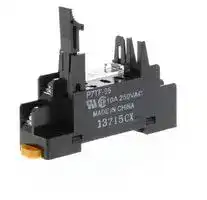


P7TF-05
Socket, G7T Series, with SPST-NO/SPST-NC/SPDT
- Manufacturer: OMRON INDUSTRIAL AUTOMATION
- Product type: Controller Accessories
- SVHC: To Be Advised
- Current Rating: -
| Delivery and price | |
|---|---|
| Units per pack | 50 |
| Price | 13.26 € |
| Current stock | 10+ |
| Lead time | 30 days |
CSM_P7TF-IS16_OS16_OS08_DS_E_2_1

## **I/O Terminal Socket P7TF-IS16/OS16/OS08**

## **I/O Terminal Sockets to Flexibly Build Systems**

- Mount either G7T I/O Relays or G3TA SSRs.

- Compact size for both Input and Output I/O Terminal Sockets: 182 (102 for 8 I/O points) (W) × 85 (D) × 68 (H) mm.

- Surge absorption circuits provided.

- LED indicators as a standard feature.

- DIN Track mounting.

## **Ordering Information**

## **I/O Terminal Sockets**

|**I/O Terminal Sockets**|**I/O Terminal Sockets**|||||
|---|---|---|---|---|---|
|**I/O Terminal Sockets**<br>~~Pd~~||**When ordering, specify the rated voltage.**<br>~~Pd~~||||
|**I/O classification**|**I/O points**<br>~~a~~|**Internal I/O common**|**Rated voltage**||**Model**|
|For inputs|16|NPN (−common)|12 VDC<br>~~PO~~||**P7TF-IS16**<br>**DC12**|
||||24 VDC<br>~~PO~~<br>~~PO~~||**P7TF-IS16**<br>**DC24**|
||||100/110 VDC<br>~~PO~~<br>~~PO~~||**P7TF-IS16**<br>**DC100/110**|
||||100/110 VAC<br>~~PO~~<br>~~pO~~||**P7TF-IS16**<br>**AC100/110**|
||||200/220 VAC<br>~~pO~~<br>~~PO~~||**P7TF-IS16**<br>**AC200/220**|
|For outputs||NPN (+ common)|12 VDC<br>~~PO~~<br>~~PO~~||**P7TF-OS16**<br>**DC12**|
||||24 VDC<br>~~PO~~||**P7TF-OS16**<br>**DC24**|
|||PNP (−common)|12 VDC<br>~~PO~~||**P7TF-OS16-1 DC12**|
||||24 VDC<br>~~PO~~||**P7TF-OS16-1 DC24**|
||8|NPN (+ common)|12 VDC<br>~~ee~~||**P7TF-OS08**<br>**DC12**|
||||24 VDC<br>~~pO~~||**P7TF-OS08**<br>**DC24**|


## **Accessories (Order Separately)**

## **Cables for I/O Relay Terminals**

- Cables with Loose Wires and Crimp Terminals: XW2Z-RY O C

- • Cables with Loose Wires: XW2Z-RA oO C • Cables with Connectors: XW2Z-R O C- OO - • Cables with Connectors (1:2): XW2Z-RO od C- and XW2Z-RI 0 C-

- Cables with Connectors (1:1): XW2Z-R oO C

- Refer to the XW2Z-R Datasheet for details.

## **Shorting Bar**

**==> picture [142 x 98] intentionally omitted <==**

**----- Start of picture text -----**<br>
Model<br>G78-04<br>Output Short-Circuit Module<br>Model<br>G77-S<br>Sockets<br>Model<br>P7TF-05<br>**----- End of picture text -----**<br>


## **Indicator Module (with Surge Suppressing Function)**

|**Type**|**Applicable relay**<br>**coil voltage**|**Model**|**Remarks**|
|---|---|---|---|
|For AC Relays|100 (110) VAC|**P70A**<br>**AC100/110**|Varistors|
||200 (220) VAC|**P70A**<br>**AC200/220**||
|For DC Relays|12/24 VDC|**P70D**<br>**DC12/24**|Diodes|


**Note: 1.** Order the Indicator Module that is suited to the Relay coil voltage.

**2.** The Indicator Module for DC Relays has a multiple power supply common to 12 and 24 VDC.

**3.** The input current is as given below (reference values). 100/110 VAC: 1.14 to 1.38 mA 200/220 VAC: 1.40 to 1.71 mA 12/24 VDC: 4.83 to 5.90 mA

**4.** Weight: Approx. 6 g

## **Accessories for DIN Track Mounting**

Refer to your OMRON website for details on the PFPOo .

**1**

**P7TF-IS16_OS16_OS08**

## **Accessories (Order Separately) Mountable I/O Relays**

|**I/O**<br>**classification**|**Rated coil voltage**|**Contact structure**|**Case color**|**Rated load (resistive load)**|**Model**|
|---|---|---|---|---|---|
|For inputs|12 VDC|SPST-NO|Transparent green|1 A at 24 VDC<br>1 A at 110 VAC|**G7T-1122S**<br>**DC12***|
||24 VDC||||**G7T-1122S**<br>**DC24***|
||100/110 VDC||||**G7T-1122S**<br>**DC100/110***|
||100/110 VAC||Transparent red||**G7T-1122S**<br>**AC100/110***|
||200/220 VAC||||**G7T-1122S**<br>**AC200/220***|
|For outputs|12 VDC||Transparent|5 A at 24 VDC<br>2 A at 220 VAC|**G7T-1112S**<br>**DC12***|
||24 VDC||||**G7T-1112S**<br>**DC24***|
||12 VDC|SPST-NC|||**G7T-1012S**<br>**DC12**|
||24 VDC||||**G7T-1012S**<br>**DC24**|


## **Mountable I/O SSRs**

|**I/O**<br>**classification**|**Rated input voltage**|**Isolation**|**Operation**<br>**indicator**|**Zero cross**<br>**function**|**Applicable load**|**Model**|
|---|---|---|---|---|---|---|
|For inputs|5 to 24 VDC|Photocoupler|Yes|---|Logic level supply current: 25 mA|**G3TA-IDZR02S**<br>**DC5-24**|
||4 to 24 VDC||No|||**G3TA-IDZR02SM**|
||100 to 240 VAC||Yes|||**G3TA-IAZR02S**<br>**AC100-240**|
|For outputs|12 VDC|Phototriac|Yes|Yes|2 A at 100 to 240 VAC|**G3TA-OA202SZ DC12**|
||24 VDC|||||**G3TA-OA202SZ DC24**|
||12 VDC|||No||**G3TA-OA202SL DC12**|
||24 VDC|||||**G3TA-OA202SL DC24**|
||12 VDC|Photocoupler||---|2 A at 5 to 48 VDC|**G3TA-ODX02S**<br>**DC12**|
||24 VDC|||||**G3TA-ODX02S**<br>**DC24**|
||12 VDC||||1 A at 48 to 200 VDC|**G3TA-OD201S**<br>**DC12**|
||24 VDC|||||**G3TA-OD201S**<br>**DC24**|


**Note:** “For inputs” and “for outputs” indicate the I/O relationship to a PLC.

Input Relays and SSRs are mainly suitable for input signals to a PLC or other device. Output Relays are mainly suitable to switching loads that receive output signals from a PLC or other device. The Input and Output Relays and SSRs have different switching performances. Select a suitable Relay for the application.

* Mounted as standard features to G7TC I/O Relay Terminals.

## **Specifications**

|**Item**<br>**Model**|**Item**<br>**Model**|**P7TF-IS16**<br>**AC**|**P7TF-IS16**<br>**DC**|**P7TF-OS16**<br>**P7TF-OS16-1**|**P7TF-OS08**|
|---|---|---|---|---|---|
|**Contact resistance***||10 mΩmax.||||
|**Terminal block**|**Permissible**<br>**current**|100 mA||10 A||
||**Dielectric strength**|1,000 VAC, 50/60 Hz for 1 minute||2,000 VAC, 50/60 Hz for 1 minute||
||**Insulation**<br>**resistance**|100 MΩmin. (at 500 VDC)||1,000 MΩmin. (at 500 VDC)||
|**Vibration resistance**||10 to 55 Hz with 1.0-mm double amplitude||||
|**Shock resistance**||200m/s2||||
|**Noise immunity**||Noise level: 1.6 kV; pulse width: 100 ns to 1 µs||||
|**Ambient operating temperature**||0 to 55°C (with no icing or condensation)||||
|**Ambient operating humidity**||35% to 85%||||
|**Tightening torque for external**<br>**connections**||0.78 to 1.17 N·m||||
|**LED color**||Red|Green|||
|**Coil surge absorption element**||Varistors|Diodes (1 A, 400 V)|||
|**Protection diode for inverse**<br>**connection**||Diodes (2 A, Reverse withstand voltage: 400 V)||||
|**Weight**||Approx. 360 g||Approx. 400 g|Approx. 350 g|


**Note:** The above values are initial values. * Measurement: 1 A at 5 VDC.

**2**

**P7TF-IS16_OS16_OS08**

## **Internal Circuits**

## **P7TF-IS16**

**==> picture [433 x 370] intentionally omitted <==**

**----- Start of picture text -----**<br>
For AC<br>(NPN input/- common)<br>Connector Pin Configuration<br>Top View<br>10<br>I/O indications on  20<br>Screw Terminals<br>1<br>2<br>3<br>4<br>0 1 11 8 56<br>1 2 12 9 Connector  78<br>2 3 13 10 pin No. 1112<br>3 4 14 11 1314<br>15<br>4 5 15 12 16<br>17<br>5 6 16 13 18<br>9<br>6 7 17 14 19<br>7 8 18 15<br>+ 9 19 +<br>− 10 20 −<br>+ 0 1 2 3 4 5 6 7 8 9 10 11 12 13 14 15 Screw terminals<br>mark − C0 C1 C2 C3 C4 C5 C6 C7 C8 C9 C10 C11 C12 C13 C14 C15<br>Connector pin No.<br>For DC<br>(NPN input/- common)<br>Connector Pin Configuration  10<br>Top View 20<br>I/O indications on  12<br>Screw Terminals 3<br>4<br>5<br>Connector  67<br>0 1 11 8 pin No. 118<br>1 2 12 9 1213<br>2 3 13 10 1415<br>3 4 14 11 1617<br>4 5 15 12 189<br>5 6 16 13 19<br>6 7 17 14<br>7 8 18 15<br>+− 109 1920 +− + 0 1 2 3 4 5 6 7 8 9 10 11 12 13 14 15 Screw terminals<br>− C0 C1 C2 C3 C4 C5 C6 C7 C8 C9 C10 C11 C12 C13 C14 C15<br>mark<br>Connector pin No.<br>**----- End of picture text -----**<br>


**Note:** Pin numbers are indicated for convenience. The mark can be used to determine orientation.

**3**

**P7TF-IS16_OS16_OS08**

## **P7TF-OS16**

**==> picture [511 x 570] intentionally omitted <==**

**----- Start of picture text -----**<br>
(NPN output/+ common)<br>Connector Pin Configuration<br>Top View<br>I/O indications on<br>Screw Terminals<br>1<br>2<br>3<br>0 1 11 8 45<br>1 2 12 9 67<br>234 345 131415 101112 Connector pin No. 11121314158<br>5 6 16 13 1617<br>6 7 17 14 1810<br>7 8 18 15 209<br>− 9 19 − 19<br>+ 10 20 +<br>+ 0 1 2 3 4 5 6 7 8 9 10 11 12 13 14 15 Screw terminals<br>mark<br>Connector pin No. − C0 C1 C2 C3 C4 C5 C6 C7 C8 C9 C10 C11 C12 C13 C14 C15<br>P7TF-OS16-1<br>(PNP output/- common)<br>Connector Pin Configuration<br>Top View<br>I/O indications on<br>Screw Terminals<br>1<br>2<br>3<br>4<br>0 1 11 8 5<br>6<br>1 2 12 9 7<br>8<br>2 3 13 10 Connector  1112<br>3 4 14 11 pin No. 1314<br>4 5 15 12 15<br>16<br>5 6 16 13 17<br>18<br>6 7 17 14 1020<br>7 8 18 15 9<br>19<br>+ 9 19 +<br>− 10 20 −<br>mark + 0 1 2 3 4 5 6 7 8 9 10 11 12 13 14 15 Screw terminals<br>Connector pin No. − C0 C1 C2 C3 C4 C5 C6 C7 C8 C9 C10 C11 C12 C13 C14 C15<br>P7TF-OS08<br>(NPN output/+ common)<br>Connector Pin Configuration<br>Top View<br>I/O indications on<br>Screw Terminals<br>1<br>2<br>3<br>4<br>0 1 11 Connector  56<br>1 2 12 pin No. 78<br>10<br>2 3 13 20<br>9<br>3 4 14 19<br>4 5 15<br>5 6 16<br>+ 0 1 2 3 4 5 6 7 Screw terminals<br>6 7 17<br>7 8 18 − C0 C1 C2 C3 C4 C5 C6 C7<br>− 9 19<br>+ 10 20<br>mark<br>Connector pin No.<br>**----- End of picture text -----**<br>


**Note:** Pin numbers are indicated for convenience. The mark can be used to determine orientation.

**4**

**P7TF-IS16_OS16_OS08**

**(Unit: mm)**

## **Dimensions**

## **I/O Terminal Sockets**

## **P7TF-IS16**

**==> picture [107 x 92] intentionally omitted <==**

## **P7TF-OS16 P7TF-OS16-1**

**==> picture [326 x 120] intentionally omitted <==**

**----- Start of picture text -----**<br>
182 68<br>Thirty-six,<br>85 M3.5 35.3 [+][ 0.2]  0<br>34<br>26<br>8 1 0 21<br>32.5<br>**----- End of picture text -----**<br>


**==> picture [326 x 121] intentionally omitted <==**

**----- Start of picture text -----**<br>
182 68<br>Thirty-six,<br>85 M3.5 35.3 [+][ 0.2]  0<br>8 1 0 21<br>32.5<br>**----- End of picture text -----**<br>


## **P7TF-OS08**

**==> picture [75 x 70] intentionally omitted <==**

**==> picture [143 x 108] intentionally omitted <==**

**----- Start of picture text -----**<br>
102<br>Twenty,<br>85 M3.5<br>8 1 0<br>**----- End of picture text -----**<br>


**==> picture [68 x 120] intentionally omitted <==**

**----- Start of picture text -----**<br>
68<br>35.3 [+]  0 [0.2]<br>21<br>32.5<br>**----- End of picture text -----**<br>


**5**

**P7TF-IS16_OS16_OS08**

## **Accessories (Order Separately)**

## **Shorting Bar**

**==> picture [511 x 280] intentionally omitted <==**

**----- Start of picture text -----**<br>
7.8 − [0] 0.1<br>G78-04<br>Use this piece for short-circuiting 3.6 [  0] −0.1<br>across terminals. 4.5<br>Max. current flow: 20 A 13.3 12.5<br>R1.8<br>10 10 10 2.5<br>37.8<br>R1.0<br>Output Short-Circuit Module 10 max. Terminal Arrangement/<br>G77-S Internal Connections<br>(Bottom View)<br>The output of the I/O Relay Terminal can<br>be obtained without relays through the<br>G77-S Output Short-Circuit Module. 32 max.<br>Refer to  Connection Example for SPDT  39 max. 3<br>Relays  on page 7 for details. 15 [±0.1]<br>Note that the G77-S Output Short-Circuit 4<br>Module is not available for inputs. 3.15<br>1.6 Four, 1-dia. holes 1 5<br>2.4 0.5<br>(The coil has no polarity.)<br>10 max. 4<br>29 max.<br>3 3.5 max .<br>**----- End of picture text -----**<br>


## **Sockets (Can be used for G7T models with SPST-NO, SPST-NC, or SPDT specifications or G3TA models.)** 19 max. Five, M3.5 × 8

**==> picture [222 x 149] intentionally omitted <==**

**----- Start of picture text -----**<br>
19 max. Five, M3.5 × 8  Internal Connections<br>7 screws with square washers (Top View)<br>4<br>3 2<br>71.5 max. 35.5<br>1<br>4 5<br>9<br>12.5 [±0.2] 1 9.5 Note:  Terminal 1 is<br>60.5 max. positive when<br>Mounting Hole Dimensions the I/O SSR is<br>employed.<br>**----- End of picture text -----**<br>


## **P7TF-05**

Can be used for sequences that use Slim Relays and for applications that develop to SPDT contacts on I/O Relay Terminals.

To use SPDT on the P7TF I/O Terminal Socket, insert an Output Short-Circuit Module on the I/O Terminal, and combine the Block Base with an SPDT Relay on the output from the Output ShortCircuit Module.

## **Specifications**

|**Specifications**||
|---|---|
|**Contact resistance***|10 mΩmax.|
|**Dielectric strength**|2,000 VAC for 1 minute|
|**Insulation resistance**|1,000 MΩmin. (at 500 VDC)|
|**Vibration resistance**|10 to 55 to 10 Hz with 0.5-mm single amplitude<br>(1.0-mm double amplitude)|
|**Shock resistance**|1,000m/s2|
|**Ambient operating**<br>**temperature**|−40 to 70°C (with no icing or condensation)|
|**Ambient operating humidity**|5% to 85%|
|**Weight**|Approx. 28 g|


12.5±0.2 **Note:** Terminal 1 is positive when the G3TA or Indicator 62±0.1 Module is employed.

* Measurement conditions: 1 A at 5 VDC using the voltage drop method

**==> picture [33 x 5] intentionally omitted <==**

**----- Start of picture text -----**<br>
4 dia. or M3<br>**----- End of picture text -----**<br>


## **Indicator Module (with Surge Suppressing Function)**

## **P70** �

Remove the transparent style strip of the P7TF-05 socket and mount this module and it will function as an operation indicator with the surge suppression.

**==> picture [37 x 5] intentionally omitted <==**

**----- Start of picture text -----**<br>
29.5 max.<br>**----- End of picture text -----**<br>


**==> picture [227 x 116] intentionally omitted <==**

**----- Start of picture text -----**<br>
8.5 max.<br>(+) DC (−)<br>32.5 max.<br>39 max.<br>AC<br>1.6 There is no coil polarity for<br>0.5 AC Relays.<br>20 Two,  2.6<br>1-dia. holes<br>**----- End of picture text -----**<br>


**6**

**P7TF-IS16_OS16_OS08**

## **Connection Example for SPDT Relays**

**The following is an application example for the P7TF-05 using an SPDT Relay on a terminal of the P7TFOS16/OS08.**

**==> picture [385 x 182] intentionally omitted <==**

**----- Start of picture text -----**<br>
NO contact load SPDT contact load<br>NO  NC<br>contact contact<br>L15 L16<br>4<br>G7T  3 2<br>(SPDT) AC (DC power supply is<br>L0 L1 L2 L3 L4 L5 L6 L7 L8 L9 L10 L11 L12 L13 L14 also possible.)<br>Independent commons<br>can also be used.<br>+ 0 1 2 3 4 5 6 7 8 9 10 11 12 13 14 15* + 1<br>− C0 C1 C2 C3 C4 C5 C6 C7 C8 C9 C10 C11 C12 C13 C14 C15*<br>5<br>−<br>P7TF-05<br>*Use the G77-S Output Short-Circuit Module in place of the G7T<br>12 VDC or 24 VDC  G7T (SPST-NO) I/O Relay.<br>(Depends on the model.) With the G77-S voltage output is available between terminals 15<br>and C15.<br>The maximum current is determined according to the controller.<br>**----- End of picture text -----**<br>


- **Note:** If more than one G77-S Output Short-Circuit Module is employed, the voltage output of the terminals on the P7TF is as follows: P7TF-OS16: The positive side (the lower row) connects to the common line internally. P7TF-OS16-1: The negative side (the upper row) connects to the common line internally.

**7**

**P7TF-IS16_OS16_OS08**

## **Safety Precautions**

Be sure to read the _Common Precautions for I/O Relay Terminal_ in the website at the following URL: http://www.ia.omron.com/.

## **Warning Indications**

|**Precautions**<br>**for Correct**<br>**Use**|**Supplementary comments on what to**<br>**do or avoid doing, to prevent failure to**<br>**operate, malfunction or undesirable**<br>**effects on product performance.**|
|---|---|


## **Precautions for Correct Use**

## **General**

I/O Relays and I/O Relay Terminal can be combined as follows to from I/O Relay Terminal:

|||**I/O Terminal Socket ***|**Replaceable Relay**|**Replaceable Relay**|**Replaceable Relay**|
|---|---|---|---|---|---|
||||**I/O Relay**|**I/O SSR**||
|**For outputs**|**DC**|P7TF-OS16<br>P7TF-OS16-1<br>P7TF-OS08|G7T-1112S (SPST-NO type)<br>G7T-1012S (SPST-NC type)|AC|G3TA-OA202SZ<br>G3TA-OA202SL|
|||||DC|G3TA-ODX02S<br>G3TA-OD201S|
|**For inputs**|**DC**|P7TF-IS16 (DC)|G7T-1122S|DC|G3TA-IDZR02S(M)|
||**AC**|P7TF-IS16 (AC)||AC|G3TA-IAZR02S|


- Relays are not mounted to the P7TF I/O Terminal Socket. Mount I/O Relays or I/O SSRs to the sockets. Specify the rated voltage in the same way as when ordering the P7TF I/O Terminal Socket.

- Combinations of AC Input Relays/SSRs and DC Input Relays/ SSRs cannot be used with the same I/O Terminal Socket. This is because specifications for coil surge absorption elements are different.

- Relays/SSRs with different voltage specifications cannot be used with the same I/O Terminal Socket. (For example, a 100-VAC Input Relay/SSR and a 200-VAC Input Relay/SSR, or a 12-VDC Output Relay/SSR and a 24-VDC Output Relay cannot be used with the same I/O Terminal Socket.)

- This is because specifications of operation indicator circuits are different.

- Only use I/O Terminal Sockets, I/O Relays, and I/O SSRs with the same specifications for rated voltage.

- I/O Terminal Socket are color coded, as shown below, according

to input/output and AC/DC specifications.

|||**I/O terminal label**|**I/O terminal**<br>**indicators**|**I/O Relay case**|
|---|---|---|---|---|
|**For**<br>**outputs**|**DC**|Yellow|Green|Transparent|
|**For**<br>**inputs**|**DC**|Red|Green|Green|
||**AC**|Red|Red|Red|


- A Shorting Bar is provided to connect four terminals. The current capacity of the shorting bar is 20 A. As long as this current capacity is not exceeded, the shorting bar can be used in combination as shown below to connect more than four terminals.

**==> picture [107 x 58] intentionally omitted <==**

- Special Connecting Cables are provided for connections to OMRON SYSMAC PLC I/O Units with Connectors. Connecting Cables with two connectors, however, come in two types: Cables for Input Blocks (XW2Z-RI) and Cables for Output Blocks (XW2ZRO).

Be sure to purchase the correct Cable for the application.

## **Microload Switching**

   - Input Relays (DC coil type) and I/O SSRs (DC input type) can be mounted onto an Output I/O Terminal Socket.

- Indicators indicate the presence or absence of signals. Use the display lever inside each relay for fault diagnosis. (Some relays do not have this lever depending on the specifications.)

- Each relay must be pressed down until its hold-down hooks engage completely. Heating or malfunction can result if relays are not mounted properly.

- Unlabeled terminals are not electrically connected. Use these for repeater terminals.

- Indicator positions and relay orientation differ between Input and Output I/O Terminal Socket. This is to aid in differentiating Input I/O Terminal Sockets from Output Terminal Sockets and in following signal flow.

- DC Input I/O Terminal Sockets and Output I/O Terminal Sockets with G3TA-OD@@@@ have positive and negative terminals, with the positive terminals normally being on the top of the I/O Relay Terminal Socket. Reversing positive and negative terminals will prevent operation.

- DIN tracks are generally used to mount I/O Relay Terminal. For screw mounting, a 210-mm DIN track is available that can be used as an adapter in combination with End Plates (PFP-M, two required).

**8**

## Terms and Conditions Agreement

## Read and understand this catalog.

Please read and understand this catalog before purchasing the products.  Please consult your OMRON representative if you have any questions or comments.

## Warranties.

(a) Exclusive Warranty. Omron’s exclusive warranty is that the Products will be free from defects in materials and workmanship for a period of twelve months from the date of sale by Omron (or such other period expressed in writing by Omron). Omron disclaims all other warranties, express or implied.

(b) Limitations. OMRON MAKES NO WARRANTY OR REPRESENTATION, EXPRESS OR IMPLIED, ABOUT NON-INFRINGEMENT, MERCHANTABILITY OR FITNESS FOR A PARTICULAR PURPOSE OF THE PRODUCTS. BUYER ACKNOWLEDGES THAT IT ALONE HAS DETERMINED THAT THE

PRODUCTS WILL SUITABLY MEET THE REQUIREMENTS OF THEIR INTENDED USE.

Omron further disclaims all warranties and responsibility of any type for claims or expenses based on infringement by the Products or otherwise of any intellectual property right. (c) Buyer Remedy. Omron’s sole obligation hereunder shall be, at Omron’s election, to (i) replace (in the form originally shipped with Buyer responsible for labor charges for removal or replacement thereof) the non-complying Product, (ii) repair the non-complying Product, or (iii) repay or credit Buyer an amount equal to the purchase price of the non-complying Product; provided that in no event shall Omron be responsible for warranty, repair, indemnity or any other claims or expenses regarding the Products unless Omron’s analysis confirms that the Products were properly handled, stored, installed and maintained and not subject to contamination, abuse, misuse or inappropriate modification. Return of any Products by Buyer must be approved in writing by Omron before shipment. Omron Companies shall not be liable for the suitability or unsuitability or the results from the use of Products in combination with any electrical or electronic components, circuits, system assemblies or any other materials or substances or environments. Any advice, recommendations or information given orally or in writing, are not to be construed as an amendment or addition to the above warranty.

See http://www.omron.com/global/ or contact your Omron representative for published information.

## Limitation on Liability; Etc.

OMRON COMPANIES SHALL NOT BE LIABLE FOR SPECIAL, INDIRECT, INCIDENTAL, OR CONSEQUENTIAL DAMAGES, LOSS OF PROFITS OR PRODUCTION OR COMMERCIAL LOSS IN ANY WAY CONNECTED WITH THE PRODUCTS, WHETHER SUCH CLAIM IS BASED IN CONTRACT, WARRANTY, NEGLIGENCE OR STRICT LIABILITY. Further, in no event shall liability of Omron Companies exceed the individual price of the Product on which liability is asserted.

## Suitability of Use.

Omron Companies shall not be responsible for conformity with any standards, codes or regulations which apply to the combination of the Product in the Buyer’s application or use of the Product. At Buyer’s request, Omron will provide applicable third party certification documents identifying ratings and limitations of use which apply to the Product. This information by itself is not sufficient for a complete determination of the suitability of the Product in combination with the end product, machine, system, or other application or use. Buyer shall be solely responsible for determining appropriateness of the particular Product with respect to Buyer’s application, product or system. Buyer shall take application responsibility in all cases.

NEVER USE THE PRODUCT FOR AN APPLICATION INVOLVING SERIOUS RISK TO LIFE OR PROPERTY OR IN LARGE QUANTITIES WITHOUT ENSURING THAT THE SYSTEM AS A WHOLE HAS BEEN DESIGNED TO ADDRESS THE RISKS, AND THAT THE OMRON PRODUCT(S) IS PROPERLY RATED AND INSTALLED FOR THE INTENDED USE WITHIN THE OVERALL EQUIPMENT OR SYSTEM.

## Programmable Products.

Omron Companies shall not be responsible for the user’s programming of a programmable Product, or any consequence thereof.

## Performance Data.

Data presented in Omron Company websites, catalogs and other materials is provided as a guide for the user in determining suitability and does not constitute a warranty. It may represent the result of Omron’s test conditions, and the user must correlate it to actual application requirements. Actual performance is subject to the Omron’s Warranty and Limitations of Liability.

## Change in Specifications.

Product specifications and accessories may be changed at any time based on improvements and other reasons. It is our practice to change part numbers when published ratings or features are changed, or when significant construction changes are made. However, some specifications of the Product may be changed without any notice. When in doubt, special part numbers may be assigned to fix or establish key specifications for your application. Please consult with your Omron’s representative at any time to confirm actual specifications of purchased Product.

## Errors and Omissions.

Information presented by Omron Companies has been checked and is believed to be accurate; however, no responsibility is assumed for clerical, typographical or proofreading errors or omissions.

**In the interest of product improvement, specifications are subject to change without notice.**

## **OMRON Corporation**

## **Industrial Automation Company**

2018.10

**http://www.ia.omron.com/**

(c)Copyright OMRON Corporation 2018 All Right Reserved.
Updated at April 22, 2026
With a legacy spanning over 80 years, Omron Industrial Automation is a globally recognized leader in the manufacture of advanced industrial control and automation components. Renowned for their reliability and engineering excellence, Omron delivers comprehensive solutions that enhance efficiency, machine safety, and precision across a wide range of manufacturing environments. Our extensive portfolio of Omron products is heavily focused on their industry-leading sensing and switching technologies. We offer a vast selection of sensors, excelling specifically in high-performance proximity sensors, light sensors, and temperature sensors. Complementing this range are robust switching solutions, featuring a deep inventory of power relays, solid-state relays, safety relays, and essential relay accessories designed for demanding operational requirements. Beyond sensing and switching, Omron is highly regarded for its precision automation and process control equipment. Our selection features highly accurate temperature controllers, versatile process controllers, and sophisticated panel displays and instrumentation. To support these fundamental systems, we also supply dependable Omron power supplies, notably AC/DC converters, alongside vital connectivity components like DIN rail terminal blocks to ensure secure, efficient, and complete industrial setups.
About Novapart
Novapart is a B2B electronic component broker specialising in stock shortages and cost reduction. We source hard-to-find parts and identify compliant alternatives across a catalogue of 410,000+ components from 500+ manufacturers.
Learn more →Stock Shortage Specialist
When a component is unavailable, discontinued or has an unacceptable lead time, we tap into our network of vetted European and Asian distributors to source what you need — without compromising on quality or traceability.
Request a quote →Compliant Alternatives
We identify pin-to-pin, electrically equivalent substitutes that meet the same certifications (RoHS, AEC-Q100, REACH) as your original specification — validated against datasheets, not just part numbers. Often at a lower cost.
BOM Analysis service →