


NFAL7565L4BT
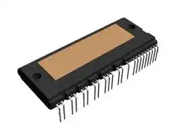
Intelligent Power Module (IPM), IGBT, 650 V, 75 A, 2.5 kV, SPM49-CAB, SPM49
- Manufacturer: ONSEMI
- Product type: Intelligent Power Modules
- SVHC: No SVHC (15-Jan-2018)
- IPM Series: SPM49
- Product Range: SPM49 Series
- IPM Case Style: SPM49-CAB
- IPM Power Device: IGBT
- Isolation Voltage: 2.5kV
- Current Rating (Ic / Id): 75A
- Voltage Rating (Vces / Vdss): 650V
| Delivery and price | |
|---|---|
| Units per pack | 50 |
| Price | 43.06 € |
| Current stock | 10+ |
| Lead time | 30 days |
## NFAL7565L4BT

## SPM 49 Series Smart Power Module (SPM) Inverter, 650 V, 75 A

## **General Description**

The NFAL7565L4BT is a smart power module providing a fully-featured, high-performance inverter output stage for AC induction, BLDC, and PMSM motors. These modules integrate optimized gate drive of the built-in IGBTs to minimize EMI and losses, while also providing multiple on-module protection features: under-voltage lockouts, over-current shutdown, temperature sensing, and fault reporting. The built-in, high-speed HVIC requires only a single supply voltage and translates the incoming logic-level gate inputs to high-voltage, high-current drive signals to properly drive the module’s internal IGBTs. Separate negative IGBT terminals are available for each phase to support the widest variety of control algorithms.

**www.onsemi.com**

## **Features**

- UL Certified No. 209204 (UL1557)

- 650 V – 75 A 3-Phase IGBT Inverter, Including Control ICs for Gate Drive and Protections

- Low-Loss, Short-Circuit-Rated IGBTs

- Very Low Thermal Resistance Using Al2O3 DBC Substrate

- Built-In Bootstrap Diodes/Resistors

- Separate Open-Emitter Pins from Low-Side IGBTs for Three-Phase Current Sensing

- Built−In NTC Thermistor for Temperature Monitoring and Management

3D Package Drawing (Click to Activate 3D Content)

**SPM49−CAB CASE MODGQ**

## **MARKING DIAGRAM**

- Adjustable Over-Current Protection via Integrated Sense-IGBTs

- Isolation Rating of 2500 Vrms/1 min

- These Devices are RoHS Compliant

## **Typical Applications**

- Motion Control − Industrial Motor (AC 200 V Class)

## **Integrated Power Functions**

- 650 V – 75 A IGBT Inverter for Three-Phase DC/AC Power Conversion (Refer to Figure 2)

## **Integrated Drive, Protection, and System Control Functions**

- For Inverter High-Side IGBTs: gate-drive circuit, high-voltage isolated high-speed level-shifting control circuit, Under-Voltage Lock-Out Protection (UVLO), Available bootstrap circuit example is given in Figures 4 and 16

- For Inverter Low-Side IGBTs: gate-drive circuit, Short-Circuit Protection (SCP) control circuit, Under-Voltage Lock-Out Protection (UVLO)

NFAL7565L4BT **ON** ZZZ ATYWW NNNNNNN ~~ooo~~ © ~~|~~ fo© NFAL7565L4BT = Specific Device Code ZZZ = Lot ID AT = Assembly & Test Location Y = Year WW = Work Week NNNNNNN = Serial Number

## **ORDERING INFORMATION**

See detailed ordering and shipping information on page 10 of this data sheet.

- Fault Signaling: corresponding to UV (low-side supply) and SC faults

- Input Interface: active-HIGH interface, works with 3.3 V/5 V logic, Schmitt-trigger input

Publication Order Number: **NFAL7565L4BT/D**

**1**

© Semiconductor Components Industries, LLC, 2019 **July, 2019 − Rev. 0**

**NFAL7565L4BT**

## **PIN CONFIGURATION**

**==> picture [431 x 483] intentionally omitted <==**

**----- Start of picture text -----**<br>
(31) LIN(W)<br>NW (1) (30) LIN(V)<br>(29) LIN(U)<br>(28) VFO<br>(27) CFOD<br>NV (2) (26) CIN<br>(25) VTS<br>(24) VSS(L)<br>(23) VDD(L)<br>NU (3)<br>(22) RSC<br>(21) VS(W)<br>W (4) (20) VB(W)<br>Case Temperature (Tc)<br>(19) VSS(H)<br>Detecting Point<br>(18) VDD(WH)<br>V (5) (17) HIN(W)<br>(16) VS(V)<br>(15) VB(V)<br>U (6)<br>(14) VDD(VH)<br>(13) HIN(V)<br>P (7)<br>(12) VS(U)<br>(11) VB(U)<br>(10) VDD(UH)<br>RTH (8) (9) HIN(U)<br>17.15<br>44.20<br>**----- End of picture text -----**<br>


**Figure 1. Pin Configuration − Top View**

**www.onsemi.com**

**2**

**NFAL7565L4BT**

## **PIN DESCRIPTION**

|**Pin Number**|**Pin Name**|**Pin Description**|
|---|---|---|
|1|NW|Negative DC-Link Input for W Phase|
|2|NV|Negative DC-Link Input for V Phase|
|3|NU|Negative DC-Link Input for U Phase|
|4|W|Output for W Phase|
|5|V|Output for V Phase|
|6|U|Output for U Phase|
|7|P|Positive DC-Link Input|
|8|RTH|Series Resistor for Thermistor (Temperature Detection)|
|9|HIN(U)|Signal Input for High-Side U Phase|
|10|VDD(UH)|High-Side Bias Voltage for U Phase IC|
|11|VB(U)|High-Side Bias Voltage for U Phase IGBT Driving|
|12|VS(U)|High-Side Bias Voltage GND for U Phase IGBT Driving|
|13|HIN(V)|Signal Input for High-Side V Phase|
|14|VDD(VH)|High-Side Bias Voltage for V Phase IC|
|15|VB(V)|High-Side Bias Voltage for V Phase IGBT Driving|
|16|VS(V)|High-Side Bias Voltage GND for V Phase IGBT Driving|
|17|HIN(W)|Signal Input for High-Side W Phase|
|18|VDD(WH)|High-Side Bias Voltage for W Phase IC|
|19|VSS(H)|High-Side Common Supply Ground, connected to HVIC|
|20|VB(W)|High-Side Bias Voltage for W Phase IGBT Driving|
|21|VS(W)|High-Side Bias Voltage GND for W Phase IGBT Driving|
|22|RSC|Resistor for Over and Short-Circuit Current Detection|
|23|VDD(L)|Low-Side Bias Voltage for IC and IGBTs Driving|
|24|VSS(L)|Low-Side Common Supply Ground, connected to LVIC|
|25|VTS|Voltage Output for LVIC Temperature Sensing Unit|
|26|CIN|Input for Current Protection|
|27|CFOD|Capacitor for Fault Output Duration Selection|
|28|VFO|Fault Output|
|29|LIN(U)|Signal Input for Low-Side U Phase|
|30|LIN(V)|Signal Input for Low-Side V Phase|
|31|LIN(W)|Signal Input for Low-Side W Phase|


**www.onsemi.com**

**3**

**NFAL7565L4BT**

## **INTERNAL EQUIVALENT CIRCUIT AND INPUT/OUTPUT PINS**

**==> picture [471 x 559] intentionally omitted <==**

**----- Start of picture text -----**<br>
(8) RTH<br>Thermistor P (7)<br>(11) VB(U) VB<br>(10) VDD(UH) VDD HVIC OUT<br>VSS<br>(9) HIN(U) IN VS<br>(12) VS(U) U (6)<br>(15) VB(V) VB<br>(14) VDD(VH) VDD HVIC OUT<br>VSS<br>(13) HIN(V) IN VS<br>(16) VS(V) V (5)<br>(20) VB(W) VB<br>OUT<br>(18) VDD(WH) VDD HVIC<br>(19) VSS(H) VSS<br>(17) HIN(W) IN VS<br>(21) VS(W) W (4)<br>(25) VTS VTS<br>OUT1<br>(26) CIN CIN<br>NU (3)<br>(27) CFOD CFOD<br>(28) VFO VFO<br>(29) LIN(U) IN1 LVIC OUT2<br>(30) LIN(V) IN2 NV (2)<br>(31) LIN(W) IN3<br>(23) VDD(L) VDD OUT3<br>(24) VSS(L) VSS<br>NW (1)<br>(22) RSC<br>**----- End of picture text -----**<br>


NOTES:

1. Inverter high-side is composed of three normal-IGBTs, freewheeling diodes, and one control IC for each IGBT.

2. Inverter low-side is composed of three sense-IGBTs, freewheeling diodes, and one control IC for each IGBT. It has gate drive and protection functions.

3. Inverter power side is composed of four inverter DC-link input terminals and three inverter output terminals.

**Figure 2. Internal Block Diagram**

**www.onsemi.com**

**4**

**NFAL7565L4BT**

**ABSOLUTE MAXIMUM RATINGS** (Tj = 25 ° C unless otherwise noted)

|**Symbol**|**Rating**|**Conditions**|**Rating**|**Unit**|
|---|---|---|---|---|
|**INVERTER PART**|||||
|VPN|Supply Voltage|Applied between P − NU, NV, NW|450|V|
|VPN(surge)|Supply Voltage (Surge)|Applied between P − NU, NV, NW|500|V|
|Vces|Collector-Emitter Voltage||650|V|
|±Ic|Each IGBT Collector Current|Tc = 25°C, Tj≤150°C|75|A|
|±Icp|Each IGBT Collector Current (Peak)|Tc = 25°C, Tj≤150°C, Under 1 ms<br>Pulse Width (Note 4)|150|A|
|Pc|Collector Dissipation|Tc = 25°C per One Chip (Note 4)|223|W|
|Tj|Operating Junction Temperature||−40~150|°C|
|**CONTROL PART**|||||
|VDD|Control Supply Voltage|Applied between VDD(H), VDD(L) − VSS|20|V|
|VBS|High-Side Control Bias Voltage|Applied between VB(U) − VS(U),<br>VB(V) − VS(V), VB(W) − VS(W)|20|V|
|VIN|Input Signal Voltage|Applied between HIN(U), HIN(V), HIN(W),<br>LIN(U), LIN(V), LIN(W) − VSS|−0.5~VDD+0.5|V|
|VFO|Fault Output Supply Voltage|Applied between VFO − VSS|−0.5~VDD+0.5|V|
|IFO|Fault Output Current|Sink Current at VFO pin|5|mA|
|VCIN|Current Sensing Input Voltage|Applied between CIN − VSS|−0.5~VDD+0.5|V|
|Tj|Operating Junction Temperature||−40~150|°C|
|**BOOSTSTRAP**|**DIODE PART**||||
|VRRM|Maximum Repetitive Reverse<br>Voltage||650|V|
|Tj|Operating Junction Temperature||−40~150|°C|
|**TOTAL SYSTEM**|||||
|VPN(PROT)|Self-Protection Supply Voltage Limit<br>(Short-Circuit Protection Capability)|VDD = VBS = 13.5~16.5 V, Tj = 150°C,<br>Vces < 650 V, Non-Repetitive, < 2�s|400|V|
|Tc|Module Case Operation<br>Temperature|See Figure 1|−40~125|°C|
|Tstg|Storage Temperature||−40~125|°C|
|Viso|Isolation Voltage|60 Hz, Sinusoidal, AC 1 Minute, Connection<br>Pins to Heat Sink Plate|2500|Vrms|


Stresses exceeding those listed in the Maximum Ratings table may damage the device. If any of these limits are exceeded, device functionality should not be assumed, damage may occur and reliability may be affected.

4. These values had been made an acquisition by the calculation considered to design factor.

## **THERMAL RESISTANCE**

|**Symbol**|**Parameter**|**Conditions**|**Min**|**Typ**|**Max**|**Unit**|
|---|---|---|---|---|---|---|
|Rth(j-c)Q|Junction-to-Case Thermal<br>Resistance (Note 5)|Inverter IGBT Part (per 1/6 module)|−|−|0.56|°C/W|
|Rth(j-c)F||Inverter FWDi Part (per 1/6 module)|−|−|0.84|°C/W|


5. For the measurement point of case temperature (Tc), please refer to Figure 1. DBC discoloration and Picker Circle Printing allowed, please refer to application note AN−9190 (Impact of DBC Oxidation on SPM[®] Module Performance).

**www.onsemi.com**

**5**

**NFAL7565L4BT**

**ELECTRICAL CHARACTERISTICS** (Tj = 25 ° C unless otherwise specified.)

|**ELECTRICAL**|**ELECTRICAL**|**CHARACTERISTICS**(Tj =|25°C unless otherwise specified.)|25°C unless otherwise specified.)|||||
|---|---|---|---|---|---|---|---|---|
|**Symbol**||**Parameter**|**Conditions**||**Min**|**Typ**|**Max**|**Unit**|
|**INVERTER PART**|||||||||
|VCE(sat)||Collector-Emitter<br>Saturation Voltage|VDD = VBS = 15 V<br>IN = 5 V|Ic = 75 A, Tj = 25°C|−|1.55|2.05|V|
||VF|FWDi Forward Voltage|IN = 0 V|Ic = −75 A, Tj = 25°C|−|2.05|2.55|V|
|HS|ton|Switching Times|VPN = 300 V, VDD = 15 V, Ic = 75 A<br>Tj = 25°C<br>IN = 0 V�5 V, Inductive Load<br>See Figure 3<br>(Note 6)||1.40|2.00|2.60|�s|
||tc(on)||||−|0.40|0.80|�s|
||toff||||−|2.10|2.70|�s|
||tc(off)||||−|0.30|0.60|�s|
||trr||||−|0.08|−|�s|
|LS|ton||VPN = 300 V, VDD = 15 V, Ic = 75 A<br>Tj = 25°C<br>IN = 0 V�5 V, Inductive Load<br>See Figure 3<br>(Note 6)||1.00|1.60|2.20|�s|
||tc(on)||||−|0.30|0.60|�s|
||toff||||−|2.10|2.70|�s|
||tc(off)||||−|0.25|0.55|�s|
||trr||||−|0.08|−|�s|
||Ices|Collector-Emitter Leakage<br>Current|Vce = Vces||−|−|1|mA|
|**CONTROL PART**|||||||||
|IQDDH||Quiescent VDD Supply<br>Current|VDD(UH,VH,WH) = 15 V,<br>HIN(U,V,W) = 0 V|VDD(UH) − VSS(H),<br>VDD(VH) − VSS(H),<br>VDD(WH) − VSS(H)|−|−|0.30|mA|
|IQDDL|||VDD(L) = 15 V,<br>LIN(U,V,W) = 0 V|VDD(L) − VSS(L)|−|−|3.50|mA|
|IPDDH||Operating VDD Supply<br>Current|VDD(UH,VH,WH) = 15 V,<br>FPWM = 20 kHz,<br>Duty = 50%, Applied to one<br>PWM Signal<br>Input for High-Side|VDD(UH) − VSS(H),<br>VDD(VH) − VSS(H),<br>VDD(WH) − VSS(H)|−|−|0.40|mA|
|IPDDL|||VDD(L) = 15 V,<br>FPWM = 20 kHz,<br>Duty = 50%, Applied to one<br>PWM Signal Input for<br>Low-Side|VDD(L) − VSS(L)|−|−|7.00|mA|
|IQBS||Quiescent VBS Supply<br>Current|VDD = VBS = 15 V,<br>HIN(U,V,W) = 0 V|VB(U) − VS(U),<br>VB(V) − VS(V),<br>VB(W) − VS(W)|−|−|0.30|mA|
|IPBS||Operating VBS Supply<br>Current|VDD = VBS = 15 V,<br>FPWM = 20 kHz,<br>Duty = 50%, Applied to one<br>PWM Signal Input for<br>High-Side|VB(U) − VS(U),<br>VB(V) − VS(V),<br>VB(W) − VS(W)|−|−|6.00|mA|
|VFOH||Fault Output Voltage|VDD = 15 V, CIN = 0 V,<br>VFO Circuit: 10 k�to 5 V Pull−up||4.90|−|−|V|
|VFOL|||VDD = 15 V, CIN = 1 V, IFO = 1 mA||−|−|0.95|V|
|ISEN||Sensing Current of Each<br>Sense IGBT|VDD = 15 V, LIN = 5 V,<br>Rsc = 0�,<br>No Connection of Shunt<br>Resistor at NU, NV, NW<br>Terminal|Ic = 75 A|−|27.0|−|mA|
|VSC(ref)||Short Circuit Trip Level|VDD = 15 V|CIN − VSS(L)|0.46|0.48|0.50|V|
|ISC||Short Circuit Current Level<br>for Trip|Rsc = 15�(±1%), No Connection of Shunt Resistor<br>at NU, NV, NW Terminal (Note 7)||113|−|−|A|


**www.onsemi.com**

**6**

**NFAL7565L4BT**

**ELECTRICAL CHARACTERISTICS** (Tj = 25 ° C unless otherwise specified.) (continued)

|**ELECTRICAL**|**CHARACTERISTICS**(Tj =|25°C unless otherwise specified.) (continued)|25°C unless otherwise specified.) (continued)|||||
|---|---|---|---|---|---|---|---|
|**Symbol**|**Parameter**|**Conditions**||**Min**|**Typ**|**Max**|**Unit**|
|**CONTROL PART**||||||||
|UVDDD|Supply Circuit Under-Voltage<br>Protection|Detection Level||10.3|−|12.5|V|
|UVDDR||Reset Level||10.8|−|13.0|V|
|UVBSD||Detection Level||10.0|−|12.0|V|
|UVBSR||Reset Level||10.5|−|12.5|V|
|VIN(ON)|ON Threshold Voltage|Applied between HIN(U,V,W) − VSS(H),<br>LIN(U,V,W) − VSS(L)||−|−|2.6|V|
|VIN(OFF)|OFF Threshold Voltage|||0.8|−|−|V|
|VTS|Voltage Output for LVIC<br>Temperature Sensing Unit|VDD(L) = 15 V, TLVIC = 25°C<br>See Figure 6 and 7 (Note 8)||0.909|1.030|1.151|V|
|tFOD|Fault-Out Pulse Width|CFOD = 22 nF (Note 9)||1.6|−|−|ms|
|RTH|Resistance of Thermistor|At TTH = 25°C|See Figure 8<br>(Note 10)|−|47|−|k�|
|||At TTH = 100°C||−|2.9|−|k�|
|**BOOTSTRAP DIODE/RESISTOR PART**||||||||
|VF|Forward Voltage|If = 0.1 A, Tj = 25°C|See Figure 9|2.1|2.5|2.9|V|
|RBOOT|Bootstrap Resistor|||12.5|15.5|18.5|�|


Product parametric performance is indicated in the Electrical Characteristics for the listed test conditions, unless otherwise noted. Product performance may not be indicated by the Electrical Characteristics if operated under different conditions.

6. ton and toff include the propagation delay of the internal drive IC. tc(on) and tc(off) are the switching times of IGBT under the given gate-driving condition internally. For the detailed information, please see Figure 3.

7. Short-circuit current protection functions only at the low-sides because the sense current is divided from main current at low-side IGBTs. Inserting the shunt resistor for monitoring the phase current at NU, NV, NW terminal, the trip level of the short-circuit current is changed.

8. TLVIC is the temperature of LVIC itself. VTS is only for sensing temperature of LVIC and cannot shutdown IGBTs automatically. The relationship between VTS voltage output and LVIC temperature is described in Figure 6. It is recommended to add a ceramic capacitor of 10 nF or more between VTS and VSS (Signal Ground) to make the VTS more stable as described in Figure 7. Refer to the application note for this products about usage of VTS.

9. The fault-out pulse width tFOD depends on the capacitance value of CFOD according to the following approximate equation: tFOD = 0.1 × 10[6] × CFOD [s].

- 10.TTH is the temperature of thermistor itself. To know case temperature (Tc), conduct experiments considering the application.

**==> picture [296 x 233] intentionally omitted <==**

**----- Start of picture text -----**<br>
100% Ic 100% Ic<br>trr<br>Vce Ic Ic Vce<br>VIN VIN<br>ton toff<br>tc(on) tc(off)<br>10% Ic<br>VIN(ON) 90% Ic 10% Vce VIN(OFF) 10% Vce 10% Ic<br>(a) turn-on (b) turn-off<br>**----- End of picture text -----**<br>


**Figure 3. Switching Time Definition**

**www.onsemi.com**

**7**

**NFAL7565L4BT**

**==> picture [473 x 180] intentionally omitted <==**

**----- Start of picture text -----**<br>
One−Leg Diagram of SPM IC<br>P<br>CBS VDD VB<br>VSS OU T LS Switching<br>IN VS<br>HS Switching VPN<br>U,V,W<br>V<br>LS Switching IN Inductor 300 V<br>VDD<br>5 V VIN VFO O UT HS Switching<br>VDD 10 k Ω CFOD<br>0 V CIN<br>V VSS<br>15 V NU, NV, NW<br>V RSC<br>5 V<br>**----- End of picture text -----**<br>


**Figure 4. Example Circuit of Switching Test**

**==> picture [466 x 153] intentionally omitted <==**

**----- Start of picture text -----**<br>
Inductive Load, VPN = 300 V, VDD = 15 V, Tj = 25 � C Inductive Load, VPN = 300 V, VDD = 15 V, Tj = 150 � C<br>6400 6400<br>5600 IGBT Turn−on, Eon 5600 IGBT Turn−on, Eon<br>4800 IGBT Turn−off, Eoff 4800 IGBT Turn−off, Eoff<br>FWD Turn−off, Erec FWD Turn−off, Erec<br>4000 4000<br>3200 3200<br>2400 2400<br>1600 1600<br>800 800<br>0 0<br>0 10 20 30 40 50 60 70 80 0 10 20 30 40 50 60 70 80<br>Collector Current, Ic [A] Collector Current, Ic [A]<br>Switching Loss, Esw [J] � Switching Loss, Esw [J] �<br>**----- End of picture text -----**<br>


**Figure 5. Switching Loss Characteristics**

**==> picture [393 x 237] intentionally omitted <==**

**----- Start of picture text -----**<br>
4.0<br>3.5<br>3.0<br>2.609<br>2.5 2.488<br>2.367<br>2.0<br>1.5<br>1.0<br>40 45 50 55 60 65 70 75 80 85 90 95 100 105 110 115 120 125 130<br>LVIC Temperature ( � C)<br>VTS Output Voltage (V)<br>**----- End of picture text -----**<br>


**Figure 6. Temperature Profile of VTS**

**www.onsemi.com**

**8**

**NFAL7565L4BT**

**==> picture [423 x 144] intentionally omitted <==**

**----- Start of picture text -----**<br>
VDD<br>VDD<br>Temperature<br>Sensing + 2.5 k � VTS<br>Voltage − A/D<br>> 10 nF is<br>   recommended MCU<br>100 k �<br>5.2 V<br>2.5 k �<br>SPM GND<br>VSS<br>**----- End of picture text -----**<br>


**Figure 7. Internal Block Diagram and Interface Circuit of VTS**

**==> picture [485 x 399] intentionally omitted <==**

**----- Start of picture text -----**<br>
R−T Curve<br>600<br>550 R−T Curve in 50~125 � C<br>20<br>500<br>450 16<br>400 12<br>350<br>8<br>300<br>250 4<br>200<br>0<br>150 50 60 70 80 90 100 110 120<br>Temperature TTH ( � C)<br>100<br>50<br>0<br>−20 −10 0 10 20 30 40 50 60 70 80 90 100 110 120<br>Temperature TTH ( � C)<br>Figure 8. R−T Curve of Built-in Thermistor<br>0.8 0.05<br>0.7<br>0.04<br>0.6<br>0.5<br>0.03<br>0.4<br>0.02<br>0.3<br>0.2<br>0.01<br>0.1<br>0 0.00<br>0 1 2 3 4 5 6 7 8 9 10 11 12 13 14 15 0 0.2 0.4 0.6 0.8 1 1.2 1.4 1.6 1.8<br>VF [V] VF [V]<br>) �<br>) �<br>Resistance (k<br>Resistance (k<br>If [A] If [A]<br>**----- End of picture text -----**<br>


**Figure 9. Characteristics of Bootstrap Diode/Resistor (Right Figure is Enlarged Figure)**

**www.onsemi.com**

**9**

**NFAL7565L4BT**

## **RECOMMENDED OPERATING RANGES**

|**Symbol**|**Parameter**|**Conditions**|**Conditions**|**Min**|**Typ**|**Max**|**Unit**|
|---|---|---|---|---|---|---|---|
|VPN|Supply Voltage|Applied between P−NU, NV, NW||−|300|400|V|
|VDD|Control Supply Voltage|Applied between VDD(UH,VH,WH)−VSS(H), VDD(L)−VSS(L)||13.5|15.0|16.5|V|
|VBS|High-Side Control Bias<br>Voltage|Applied between VB(U)−VS(U), VB(V)−VS(V), VB(W)−VS(W)||13.0|15.0|18.5|V|
|dVDD/dt,<br>dVBS/dt|Control Supply Variation|||−1|−|+1|V/�s|
|tdead|Blanking Time for<br>Preventing Arm − Short|For Each Input Signal||2.5|−|−|�s|
|FPWM|PWM Input Signal|−40°C≤Tc≤125°C, −40°C≤Tj≤150°C||−|−|20|kHz|
|Io|Allowable r.m.s.<br>Output Current|VPN = 300 V, VDD = VBS = 15 V,<br>P.F = 0.8, Sinusoidal PWM<br>Tc≤125°C, Tj≤150°C (Note 11)|FPWM = 5 kHz|−|−|38|Arms|
||||FPWM = 15 kHz|−|−|26||
|VSEN|Voltage for Current<br>Sensing|Applied between NU, NV, NW−VSS<br>(Including Surge Voltage)||−5.0|−|+5.0|V|
|PWIN(ON)|Minimum Input Pulse<br>Width|(Note 12)||1.3|−|−|�s|
|PWIN(OFF)||VDD = VBS = 15 V, IC ≤150 A, Wiring Inductance between<br>NU, NV, NW and DC Link N < 10 nH (Note 12)||2.0|−|−||
|Tj|Junction Temperature|||−40|−|+150|°C|


Functional operation above the stresses listed in the Recommended Operating Ranges is not implied. Extended exposure to stresses beyond the Recommended Operating Ranges limits may affect device reliability.

11. This allowable output current value is the reference data for the safe operation of this product. This may be different from the actual application and operating condition.

12.This product might not make output response if input pulse width is less than the recommended value.

## **PACKAGE MARKING AND ORDERING INFORMATION**

|**Device**|**Device Marking**|**Package**|**Shipping**|
|---|---|---|---|
|NFAL7565L4BT|NFAL7565L4BT|SPM49−CAB|6 Units/Tube|


**www.onsemi.com**

**10**

**NFAL7565L4BT**

## **MECHANICAL CHARACTERISTICS AND RATINGS**

|**Parameter**|**Conditions**|**Conditions**|**Min**|**Typ**|**Max**|**Unit**|
|---|---|---|---|---|---|---|
|Device Flatness<br>~~a ~~|See Figure 10<br> ~~a~~||−50|−|100|m|
|Mounting Torque|Mounting Screw: M4<br>See Figure 11|Recommended 1.18 N⋅m|0.98|1.18|1.47|N⋅m|
|||Recommended 12.03 kg⋅cm|10.00|12.03|14.98|kg⋅cm|
|Terminal Pulling Strength|Load 19.6 N||10|−|−|s|
|Terminal Bending Strength|Load 9.8 N, 90 degrees Bend||2|−|−|times|
|Weight|||−|44.5|−|g|


**Figure 10. Flatness Measurement Position**

## NOTES:

13.Do not over torque when mounting screws. Too much mounting torque may cause DBC cracks, as well as bolts and Al heat-sink destruction.

14.Avoid one-sided tightening stress. Figure 11 shows the recommended torque order for the mounting screws. Uneven mounting can cause the DBC substrate of package to be damaged. The pre-screwing torque is set to 20~30% of maximum torque rating.

**Figure 11. Mounting Screws Torque Order**

**www.onsemi.com**

**11**

**NFAL7565L4BT**

## **TIME CHARTS OF SPMs PROTECTIVE FUNCTION**

**==> picture [256 x 152] intentionally omitted <==**

**----- Start of picture text -----**<br>
Input Signal<br>Protection<br>RESET SET RESET<br>Circuit State<br>UVDDR<br>Control a1 UVDDD a6<br>Supply Voltage a3<br>a2<br>a4 a7<br>Output Current<br>Fault Output Signal a5<br>**----- End of picture text -----**<br>


a1: Control supply voltage rises: after the voltage rises UVDDR, the circuits start to operate when the next input is applied. a2: Normal operation: IGBT ON and carrying current.

a3: Under-voltage detection (UVDDD).

a4: IGBT OFF in spite of control input condition.

a5: Fault output operation starts with a fixed pulse width according to the condition of the external capacitor CFOD. a6: Under-voltage reset (UVDDR).

a7: Normal operation: IGBT ON and carrying current by triggering next signal from LOW to HIGH.

**Figure 12. Under-voltage Protection (Low-side)**

**==> picture [310 x 152] intentionally omitted <==**

**----- Start of picture text -----**<br>
Input Signal<br>Protection<br>Circuit State RESET SET RESET<br>UVBSR<br>Control b1 UVBSD b5<br>Supply Voltage b3<br>b6<br>b2<br>b4<br>Output Current<br>High−level (no fault output)<br>Fault Output Signal<br>**----- End of picture text -----**<br>


b1: Control supply voltage rises: after the voltage reaches UVBSR, the circuits start to operate when the next input is applied. b2: Normal operation: IGBT ON and carrying current. b3: Under-voltage detection (UVBSD).

- b4: IGBT OFF in spite of control input condition, but there is no fault output signal. b5: Under-voltage reset (UVBSR).

b6: Normal operation: IGBT ON and carrying current by triggering next signal from LOW to HIGH.

**Figure 13. Under-voltage Protection (High-side)**

**www.onsemi.com**

**12**

**NFAL7565L4BT**

**==> picture [300 x 287] intentionally omitted <==**

**----- Start of picture text -----**<br>
Lower Arms<br>Control Input c6 c7<br>Protection<br>Circuit state SET RESET<br>c4<br>Internal IGBT<br>Gate−Emitter c3<br>Input Voltage<br>c2 Internal delay<br>at protection circuit<br>SC current trip level<br>c8<br>c1<br>Output Current<br>SC reference voltage<br>Sensing Voltage<br>of Sense Resistor<br>RC filter circuit<br>time constant<br>delay<br>Fault Output Signal c5<br>**----- End of picture text -----**<br>


(With the external sense resistance and RC filter connection) c1: Normal operation: IGBT ON and carrying current.

c2: Short-circuit current detection (SC trigger).

c3: All low-side IGBTs gate are hard interrupted.

c4: All low-side IGBTs turn OFF.

c5: Fault output operation starts with a fixed pulse width according to the condition of the external capacitor CFOD.

c6: Input HIGH − IGBT ON state, but during the active period of fault output, the IGBT doesn’t turn ON.

- c7: Fault output operation finishes, but IGBT doesn’t turn on until triggering the next signal from LOW to HIGH.

c8: Normal operation: IGBT ON and carrying current.

**Figure 14. Short-circuit Current Protection (Low-side Operation Only)**

## **INPUT/OUTPUT INTERFACE CIRCUIT**

**==> picture [390 x 127] intentionally omitted <==**

**----- Start of picture text -----**<br>
+5V (MCU or control power)<br>10 k � SPM<br>HIN(U), HIN(V), HIN(W)<br>LIN(U), LIN(V), LIN(W)<br>MCU VFO<br>VSS<br>**----- End of picture text -----**<br>


NOTE:

- 15.RC coupling at each input might change depending on the PWM control scheme used in the application and the wiring impedance of the application’s printed circuit board. The input signal section of the SPM49 product integrates 5 k � (typ.) pull-down resistor. Therefore, when using an external filtering resistor, please pay attention to the signal voltage drop at input terminal.

**Figure 15. Recommended MCU I/O Interface Circuit**

**www.onsemi.com**

**13**

**NFAL7565L4BT**

**==> picture [446 x 339] intentionally omitted <==**

**----- Start of picture text -----**<br>
5V line<br>Monitoring 1Temp. R6 (8) RTH Thermistor P (7)<br>Gating UH R1 (9) HIN(U)(10) VDD(UH) VDDIN<br>C4 VSS HVIC OUT<br>(11) VB(U) VB VS<br>C3 C4 (12) VS(U) U (6)<br>Gating VH R1 ((1413)) VDD HIN(V(VH) ) VDDIN<br>C4 VSS HVIC OUT<br>(15) VB(V) VB VS<br>C3 C4 (16) VS(V) V (5) M<br>R1 (17) HIN(W)<br>M Gating WH C1 C1 C1 C4 (19) VSS(H)(18) VDD(WH) VSSVDDIN HVIC OUT C8 VDC<br>(20) VB(W) VB VS<br>C C3 C4 (21) VS(W) W (4)<br>U Fault 5V lineR1 R2 C6 (27) CFOD CFOD OUT1<br>C1 C1 (28) VFO VFO NU (3) R3 A<br>Gating UL R1 (29) LIN(U) IN1<br>Gating VL R1 (30) LIN(V) IN2 OUT2<br>Gating WL R1 C1 C1 C1 15V line (31) LIN(W)(23) VDD(L) IN3VDD LVIC NV (2) ResistorShuntR3 E Power<br>C2 C4 (24) VSS(L) VSS GND Line<br>OUT3<br>Monitoring 2Temp. (25) VTS VTS NW (1) R3<br>C7 CIN<br>RSC (22) R4<br>(26) CIN Sense<br>Resistor<br>D<br>C5 R5 B U−Phase CurrentV−Phase Current GND LineControl<br>C W−Phase Current<br>**----- End of picture text -----**<br>


## NOTES:

- 16.To avoid malfunction, the wiring of each input should be as short as possible (less than 2−3 cm).

- 17.VFO output is an open-drain type. This signal line should be pulled up to the positive side of the MCU or control power supply with a resistor that makes IFO up to 1 mA. Please refer to Figure 15.

- 18.Fault out pulse width can be adjusted by capacitor C6 connected to the CFOD terminal.

- 19.Input signal is active-HIGH type. There is a 5 k � resistor inside the IC to pull-down each input signal line to GND. RC coupling circuits should be adopted for the prevention of input signal oscillation. R1C1 time constant should be selected in the range 50~150 ns (recommended R1 = 100 � , C1 = 1 nF).

- 20.Each wiring pattern inductance of point A should be minimized (recommend less than 10 nH). Use the shunt resistor R3 of surface mounted (SMD) type to reduce wiring inductance. To prevent malfunction, wiring of point E should be connected to the terminal of the shunt resistor R3 as close as possible.

- 21.To insert the shunt resistor to measure each phase current at NU, NV, NW terminal, it makes to change the trip level ISC about the short-circuit current.

- 22.To prevent errors of the protection function, the wiring of points B, C, and D should be as short as possible. The wiring of B between CIN filter and RSC terminal should be divided at the point that is close to the terminal of sense resistor R4.

- 23.For stable protection function, use the sense resistor R4 with resistance variation within 1% and low inductance value.

- 24.In the short-circuit protection circuit, select the R5C5 time constant in the range 2.0~2.5 � s. R5 should be selected with a minimum of 10 times larger resistance than sense resistor R4. Do enough evaluation on the real system because short-circuit protection time may vary wiring pattern layout and value of the R5C5 time constant.

- 25.Each capacitor should be mounted as close to the pins of the SPM product as possible.

- 26.To prevent surge destruction, the wiring between the smoothing capacitor C8 and the P & GND pins should be as short as possible. The use of a high-frequency non-inductive capacitor of around 0.1~0.22 � F between the P & GND pins is recommended.

- 27.Relays are used in most systems of electrical equipment in industrial application. In these cases, there should be sufficient distance between the MCU and the relays.

- 28.The Zener diode or transient voltage suppressor should be adopted for the protection of ICs from the surge destruction between each pair of control supply terminals (recommended Zener diode is 22 V/1 W, which has the lower Zener impedance characteristic than about 15 � ).

- 29.C2 of around seven times larger than bootstrap capacitor C3 is recommended.

- 30.Please choose the electrolytic capacitor with good temperature characteristic in C3. Choose 0.1~0.2 � F R-category ceramic capacitors with good temperature and frequency characteristics in C4.

## **Figure 16. Typical Application Circuit**

SPM is registered trademarks of Semiconductor Components Industries, LLC (SCILLC) or its subsidiaries in the United States and/or other countries.

**www.onsemi.com**

**14**

## MECHANICAL CASE OUTLINE **PACKAGE DIMENSIONS**

**==> picture [110 x 29] intentionally omitted <==**

**----- Start of picture text -----**<br>
DIP31, 79x30/SPM49 CAB<br>CASE MODGQ<br>ISSUE O<br>**----- End of picture text -----**<br>


**==> picture [81 x 8] intentionally omitted <==**

**----- Start of picture text -----**<br>
DATE 06 DEC 2018<br>**----- End of picture text -----**<br>


## **GENERIC MARKING DIAGRAM***

XXXX = Specific Device Code XXXXXXXXXXX ZZZ = Assembly Lot Code ZZZ ATYWW AT = Assembly & Test Location NNNNNNN Y = Year W = Work Week NNN = Serial Number

*This information is generic. Please refer to device data sheet for actual part marking. Pb−Free indicator, “G” or microdot “ ”, may or may not be present. Some products may not follow the Generic Marking. |

## **DOCUMENT NUMBER: 98AON98538G**

## **DESCRIPTION: DIP31, 79x30/SPM49 CAB**

Electronic versions are uncontrolled except when accessed directly from the Document Repository. Printed  versions are uncontrolled  except when stamped  “CONTROLLED COPY” in red.

**PAGE 1 OF 1**

ON Semiconductor and          are trademarks of Semiconductor Components Industries, LLC dba ON Semiconductor or its subsidiaries in the United States and/or other countries. ON Semiconductor reserves the right to make changes without further notice to any products herein. ON Semiconductor makes no warranty, representation or guarantee regarding the suitability of its products for any particular purpose, nor does ON Semiconductor assume any liability arising out of the application or use of any product or circuit, and specifically disclaims any and all liability, including without limitation special, consequential or incidental damages. ON Semiconductor does not convey any license under its patent rights nor the rights of others.

www.onsemi.com

© Semiconductor Components Industries, LLC, 2018

ON Semiconductor and      are trademarks of Semiconductor Components Industries, LLC dba ON Semiconductor or its subsidiaries in the United States and/or other countries. ON Semiconductor owns the rights to a number of patents, trademarks, copyrights, trade secrets, and other intellectual property. A listing of ON Semiconductor’s product/patent coverage may be accessed at www.onsemi.com/site/pdf/Patent−Marking.pdf. ON Semiconductor reserves the right to make changes without further notice to any products herein. ON Semiconductor makes no warranty, representation or guarantee regarding the suitability of its products for any particular purpose, nor does ON Semiconductor assume any liability arising out of the application or use of any product or circuit, and specifically disclaims any and all liability, including without limitation special, consequential or incidental damages. Buyer is responsible for its products and applications using ON Semiconductor products, including compliance with all laws, regulations and safety requirements or standards, regardless of any support or applications information provided by ON Semiconductor. “Typical” parameters which may be provided in ON Semiconductor data sheets and/or specifications can and do vary in different applications and actual performance may vary over time. All operating parameters, including “Typicals” must be validated for each customer application by customer’s technical experts. ON Semiconductor does not convey any license under its patent rights nor the rights of others. ON Semiconductor products are not designed, intended, or authorized for use as a critical component in life support systems or any FDA Class 3 medical devices or medical devices with a same or similar classification in a foreign jurisdiction or any devices intended for implantation in the human body. Should Buyer purchase or use ON Semiconductor products for any such unintended or unauthorized application, Buyer shall indemnify and hold ON Semiconductor and its officers, employees, subsidiaries, affiliates, and distributors harmless against all claims, costs, damages, and expenses, and reasonable attorney fees arising out of, directly or indirectly, any claim of personal injury or death associated with such unintended or unauthorized use, even if such claim alleges that ON Semiconductor was negligent regarding the design or manufacture of the part. ON Semiconductor is an Equal Opportunity/Affirmative Action Employer. This literature is subject to all applicable copyright laws and is not for resale in any manner.

## **PUBLICATION ORDERING INFORMATION**

## **LITERATURE FULFILLMENT** :

Literature Distribution Center for ON Semiconductor 19521 E. 32nd Pkwy, Aurora, Colorado 80011 USA **Phone** : 303−675−2175 or 800−344−3860 Toll Free USA/Canada **Fax** : 303−675−2176 or 800−344−3867 Toll Free USA/Canada **Email** : orderlit@onsemi.com

**N. American Technical Support** : 800−282−9855 Toll Free **ON Semiconductor Website** : **www.onsemi.com** USA/Canada

**Order Literature** : http://www.onsemi.com/orderlit For additional information, please contact your local Sales Representative

**Europe, Middle East and Africa Technical Support:** Phone: 421 33 790 2910

◊
Updated at April 27, 2026
onsemi is a premier global supplier of intelligent power and sensing technologies, driving disruptive innovations across the automotive, industrial, and cloud infrastructure markets. Recognized for their commitment to sustainability and reliable supply chains, the company accelerates advancements in vehicle electrification, industrial automation, and 5G networks by solving the industry's most complex design challenges. At the core of their portfolio is an industry-leading selection of discrete semiconductors. This extensive range features thousands of high-performance bipolar transistors, single and dual MOSFETs, and a comprehensive array of diodes, including Zener, Schottky, and fast-recovery rectifiers. Engineered for superior thermal performance and energy efficiency, these foundational components are critical for demanding power conversion, switching, and signal conditioning applications. Beyond essential discretes, onsemi provides a robust suite of advanced power management and circuit protection solutions. Their lineup includes intelligent power modules, single IGBTs, and transient voltage suppression (TVS) diodes designed to safeguard sensitive circuitry. Complimented by integrated passive filters, AC/DC LED driver ICs, and specialized sub-2.4GHz RF transceivers, onsemi equips engineers with the scalable, high-quality technologies needed to build a cleaner, smarter, and more connected world.
About Novapart
Novapart is a B2B electronic component broker specialising in stock shortages and cost reduction. We source hard-to-find parts and identify compliant alternatives across a catalogue of 420,000+ components from 500+ manufacturers.
Learn more →Stock Shortage Specialist
When a component is unavailable, discontinued or has an unacceptable lead time, we tap into our network of vetted European and Asian distributors to source what you need — without compromising on quality or traceability.
Request a quote →Compliant Alternatives
We identify pin-to-pin, electrically equivalent substitutes that meet the same certifications (RoHS, AEC-Q100, REACH) as your original specification — validated against datasheets, not just part numbers. Often at a lower cost.
BOM Analysis service →