
Image not available
Illustrative purposes only

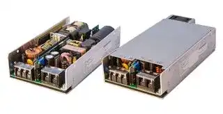
IMA-S1000-48-YYPLI
POWER SUPPLY, AC-DC, 48V, 21A
⚠️ Reference pricing provided. In case of supply shortages, we will connect you with our trusted procurement partners to ensure your project's continuity.
- Manufacturer: DELTA ELECTRONICS / POWER
- Product type: AC / DC Open Frame Power Supplies
- Product Range: IMA Series
- No. of Outputs: 1 Output
- Input Voltage VAC: 80V AC to 275V AC
- Power Supply Approvals: ITE & Medical
- Power Supply Output Type: Adjustable, Fixed
- Output Current - Output 1: 21A
- Output Voltage - Output 1: 48V
- Power Rating (Forced Cooling): 1kW
| Delivery and price | |
|---|---|
| Units per pack | 25 |
| Price | 262.71 € |
| Current stock | 10+ |
| Lead time | 7 days |
Datasheet

IMA 1000 Watts Power Supply Series for medical and industrial applications

Product data sheet

**IMA-x1000 Power Supply Series**

## **1000 Watts Power Supply Series**

## **for medical and industrial applications**

## **Features**

- Safety rated for Medical, Industrial and IT

- Wide operating input voltage range: 80 Vac to 275 Vac or 120 Vdc to 300 Vdc

- Wide adjustable output voltage range (+/- 20%)

- 5 Vdc standby output

- High efficiency: up to 94%

- Size: 5 x 8.25 x 1.6 in (1U design)

- Variable speed fan control

- Low acoustic noise level of less than 39 dB(A)

- Active current sharing

- 2 × MOPP

- PMBus™ compatible for control, programming and monitoring

- 500,000 hour MTBF

- Optional conformal coating

- 3 years warranty

## **Model variants**

|**Model number**1)|**Input voltage range**|**Input voltage range**|**Main DC Output**|**Main DC Output**|**Auxiliary**|**DC Output**|**Remote**<br>**ON/OFF**<br>**standard**<br>**setting**2)|
|---|---|---|---|---|---|---|---|
||**AC**<br>**(Vac)**|**DC**<br>**(Vdc)**|**Voltage**<br>**(Vdc)**|**Current**<br>**(A)**|**Voltage**<br>**(Vdc)**|**Current**<br>**(A)**||
|IMA-x1000-12-YYPLI|80 to 275|120 to 300|12|84|5|2|OFF|
|IMA-x1000-12-YYPLY|||||||ON|
|IMA-x1000-24-YYPLI|||24|42|||OFF|
|IMA-x1000-24-YYPLY|||||||ON|
|IMA-x1000-48-YYPLI|||48|21|||OFF|
|IMA-x1000-48-YYPLY|||||||ON|


- 1) IMA-x1000: x = S for standard version (e.g. IMA-S1000-24-YYPLY),

   - x = C for conformal coated version (e.g. IMA-C1000-24-YYPLY)

> 2) Model YYPLI and YYPLY have different settings for Remote ON/OFF, see _“Other features”, p. 4._

## **AC/DC Input (J1)**

**==> picture [497 x 19] intentionally omitted <==**

**----- Start of picture text -----**<br>
IMA-x1000-12 IMA-x1000-24 IMA-x1000-48<br>**----- End of picture text -----**<br>


||**IMA-x1000-12**|**IMA-x1000-24**|**IMA-x1000-48**|
|---|---|---|---|
|||||
|**Nominal input voltage**|100 Vac to 240 Vac|||
|**AC Operating input voltage range**|80 Vac to 275 Vac|||
|**Nominal input frequency**|50 / 60  Hz|||
|**Input frequency range**|47 Hz to 63 Hz|||
|**DC Input voltage range**|120 Vdc to 300 Vdc|||
|**Maximum input current**|15 A at 80 Vac / 9.5 A at 120 Vdc|||
|**Effciency @ 70% load1)**||_see Fig. 12 to Fig. 14_||
|@ 230 Vac|93%|94%|94%|
|@ 115 Vac|91%|92%|91.5%|
|**Max inrush current2)**||< 20 A||
|**Input fuse**|DC input compliant, dual 16 A fuses used|||
|**Power factor3)**|0.9 (typical)|||


- 1) Excluding fan power

- 2) Hot and cold turn on

- 3) EN 61000-3-2, Class A compliant

IMA-x1000-xx-Series_Data_Sheet_V4.0__XX_EN_2017-02-13

2

**IMA-x1000 Power Supply Series**

## **Main DC Output (J2)**

**==> picture [498 x 19] intentionally omitted <==**

**----- Start of picture text -----**<br>
IMA-x1000-12 IMA-x1000-24 IMA-x1000-48<br>**----- End of picture text -----**<br>


||**IMA-x1000-12**|**IMA-x1000-24**|**IMA-x1000-48**|
|---|---|---|---|
|||||
|**Nominal output voltage**|12 V|24 V|48 V|
|**Output voltage adjustment range**|9.6 V to 14.4 V|19.2 V to 28.8 V|38.4 V to 56.0 V|
|**Maximum output power**||1,000 W||
|**Output voltage regulation**||||
|Total||2.25%||
|Over line<br>Full input range, full load||0.25 %||
|Over load<br>Nominal input, full load<br>range||1%||
|Over temperature<br>Nominal input, full load,<br>full temperature range||1%||
|**Maximum output current**|84 A|42 A|21 A|
|**Maximum output capacitive load**||10,000 µF||
|**Dynamic load regulation 1)**||< 5%||
|**PARD (20 MHz) 2)**|< 120 mV|< 150 mV|< 200 mV|
|**Turn on overshoot**||< 2%||
|**Output rise time**||< 100 ms||
|**Hold up time**||20 msec nominal||
|**Start up time**||||
|AC OFF --> ON<br>Nominal input, max. load||< 2.5 s||
|REMOTE OFF --> ON<br>Nominal input, max. load||< 150 ms||
|**Output over voltage protection**||YES, latch mode||
||15 V to 17.5 V|30 V to 35 V|58 V to 65 V|
|**Output over current protection**|YES, at 108% to 140% of maximal output current; auto recovery|||
|**Short circuit protection**|YES, auto recovery|||
|**Over temperature protection**|YES, auto recovery|||
|**Remote sense3)**<br>Total voltage drop com-<br>pensation for +V_SENSE<br>and -V_SENSE connec-<br>tions (J3 Pins 13 and 14)<br>to the output load|200 mV|||


- 1) 50% step from 5% load,1 A/µs, 10 µF Tan and 1µF ceramic capacitor

- 2) 10 µF Tan and 1µF ceramic capacitor

- 3) Do not short or reversely connect +V_SENSE and -V_SENSE. Doing this can cause damage to the power supply.

## **Auxiliary DC Output (J3)**

**==> picture [498 x 19] intentionally omitted <==**

**----- Start of picture text -----**<br>
IMA-x1000-xx<br>**----- End of picture text -----**<br>


||**IMA-x1000-xx**|
|---|---|
|||
|**Connector type**|Molex, Part number 87833-1420, 14 pin, see_Fig. 15, page 11_|
|**Nominal output voltage**|5 V|
|**Output voltage adjustment range **|–|
|**Output voltage regulation**||
|Total|2.25%|
|Over line<br>Full input range, full load|0.25%|
|Over load<br>Nominal input, full load<br>range|1%|
|Over temperature<br>Nominal input, full load,<br>full temperature range|1%|
|**Maximum output current**|2 A|
|**Maximum output capacitive load**|1,000µF|
|**Output over voltage protection**|Yes, at 5.7 V to 6.5 V; latch mode|
|**Output over currentprotection**|YES, at 108% to 140% of maximal output current; auto recovery|
|**Short circuitprotection**|YES, auto recovery|
|**Over temperatureprotection**|YES, auto recovery|


IMA-x1000-xx-Series_Data_Sheet_V4.0__XX_EN_2017-02-13

3

**IMA-x1000 Power Supply Series**

## **Galvanic isolation**

**==> picture [497 x 18] intentionally omitted <==**

**----- Start of picture text -----**<br>
IMA-x1000-xx<br>**----- End of picture text -----**<br>


||**IMA-x1000-xx**|
|---|---|
|||
|**Input to Output**<br>Reinforced|4000 Vac; 2 x MOPP|
|**Input to Case**<br>Basic|1500 Vac; 1 x MOPP|
|**Output to Case**<br>Basic|1500 Vac; 1 x MOPP|


## **Leakage currents**

|||**IMA-x1000-xx**|**IMA-x1000-xx**||
|---|---|---|---|---|
|**AC Leakage current from Input to earth ground**|Measured at mains<br>voltage|<br>at 60 Hz|at 63 Hz||
|Normal condition (low line)|132 Vac|< 150 µA|< 150 µA||
|Single fault condition (low line)|132 Vac|< 250 µA|< 260 µA||
|Normal condition (high line)|264 Vac|< 300 µA|< 300 µA||
|Single fault condition (high line)|264 Vac|< 500 µA|< 520 µA||
|**AC Leakage current from Output to earth ground**|Measured at mains<br>voltage|<br>Typical at 60 Hz1)|Maximum value at<br>63 Hz1)|Limit per<br>IEC 60601-1|
|Normal condition (low line)|264 Vac|55 µA|< 70 µA|100 µA|
|Single fault condition (low line)|264 Vac|43 µA|< 80 µA|500 µA|
|Normal condition (high line)|264 Vac|172 µA|< 230 µA|500 µA|
|Single fault condition (high line)|264 Vac|< 1250 µA|< 1800 µA|5000 µA|


1) Meets IEC 60601-1 BF leakage current limit

## **Other features**

||**IMA-x1000-xx**|**IMA-x1000-xx**|**IMA-x1000-xx**|**IMA-x1000-xx**|
|---|---|---|---|---|
|**Current Share Bus Pin**<br>J3 Pin 11<br>(CURRENT SHARE_V)|Voltage at_CS_Pin will vary linearly with load current on main output, and will be<br>6 V at rated load current, when the output voltage is at its rated value.||||
|**Power Good Pin**<br>J3 Pin 9<br>(PWR_GOOD)|Open collector. As soon as AC input voltage and DC output voltage are in the<br>predefned range, the PWR_GOOD signal is set to HIGH.||||
|**Green LED**|Will turn ON as soon as PWR_GOOD signal is set to HIGH||||
|**Component Derating Guideline**|Refer to IPC 9592B and to Delta Guideline||||
|**OR-ing**|Redundant operation with active circuit sharing, _see Application Note “Redundant_<br>_operation”, p. 10_||||
|**SDA, SCL for I2C**|Internal 10 kΩ pull-up resistor to internal 3.3 V||||
||||||
||**IMA-x1000-xx-YYPLI**||**IMA-x1000-xx-YYPLY**||
|**Remote On/Off Pin1)**<br>J3 Pin 10<br>(REMOTE ON/OFF)|REMOTE ON/OFF<br>(J3 Pin 10) and<br>5VSB_RTN<br>(J3 Pin 3 or J3<br>Pin 4 or J3 Pin 7)|Main DC Output|REMOTE ON/OFF<br>(J3 Pin 10) and<br>5VSB_RTN (J3<br>Pin 3 or J3 Pin 4 or<br>J3 Pin 7)|Main DC Output|
||Shorted|OFF|Shorted|ON|
||Open|ON|Open|OFF|


- 1) Logic can be switched with PMBus™

IMA-x1000-xx-Series_Data_Sheet_V4.0__XX_EN_2017-02-13

4

**IMA-x1000 Power Supply Series**

## **Environmental conditions**

**==> picture [498 x 18] intentionally omitted <==**

**----- Start of picture text -----**<br>
IMA-x1000-12 IMA-x1000-24 IMA-x1000-48<br>**----- End of picture text -----**<br>


||**IMA-x1000-12**|**IMA-x1000-24**|**IMA-x1000-48**|
|---|---|---|---|
|||||
|**Ambient operating temperature range1)**|_(see Fig. 8, page 10)_|||
|Standard mounting orientation (see_Fig. 1,_<br>_page 8_)|--20 °C ... +70 °C (-4°F to +158 °F)|||
|Other mounting orientations|-20 to +65 °C (-4 to +149 °F)|||
|**Ambient storage temperature range**|-40 °C ... +85 °C (-40 °F to +185 °F)|||
|**Output power derating**||||
|Versus input voltage|When AC input voltage is < 90 Vac, the output power will be reduced by 20 W per<br>1 V._(see Fig. 7, page 10)_|||
|Versus ambient temperature|_(see Fig. 8, page 10)_|||
|Standard mounting orientation<br>(see_Fig. 1, page 8_)|When ambient temperature is > 50 °C (122 °F), the output power will be reduced<br>by 25 W per 1 °C.|||
|Other mounting orientations|When ambient temperature is > 45 °C (113 °F), the output power will be reduced<br>by 25 W per 1 °C.|||
|**Output current derating**<br>Versus output voltage|When output voltage<br>is > 12 Vdc, the output<br>current is reduced by<br>6.08 A per 1 V_(see Fig. 9,_<br>_page 10)._|When output voltage is<br>> 24 Vdc, the output cur-<br>rent is reduced by 1.52 A<br>per 1 V_(see Fig. 10,_<br>_page 10)_.|When output voltage is<br>> 48 Vdc, the output cur-<br>rent is reduced by 0.4 A<br>per 1 V_(see Fig. 11,_<br>_page 10)_.|
|**Relative humidity**||< 95% (non-condensing)||
|**Operating altitude1) 2)**|-200|m to 5,000 m (-650 ft to 16,400 ft)||
|**Shock test (non-operating)**|IEC 60068-2-27 compliant, 50 g, 11 ms, 3 shocks for each direction|||
|**Vibration**|IEC 60068-2-6 compliant, 2.09 Grms, 5 - 500 Hz, 20 minutes per side (3 planes)|||
|**Pollution degree**|2|||


1) Ambient operating temperature decreases by 1 °C per 305 m (1000 ft) altitude increase

2) Maximum operating altitude requirements for different types of products, see “Safety standards and directives 1)”, p. 6

## **Reliability**

**==> picture [498 x 19] intentionally omitted <==**

**----- Start of picture text -----**<br>
IMA-x1000-xx<br>**----- End of picture text -----**<br>


||**IMA-x1000-xx**|
|---|---|
|||
|**CMTBF1)**|500,000 hours|
|**Expected capacitor life time2)**|10 years|
|**Fan L10 life @ 40 °C**|70,000 hours|
|**Warranty**|3 years|


1) Telecordia SR-332, Issue 2, 25 °C, 90% confidence level

2) Nominal input voltage, 45 °C (113 °F), 80% load

IMA-x1000-xx-Series_Data_Sheet_V4.0__XX_EN_2017-02-13

5

**IMA-x1000 Power Supply Series**

## **EMC**

This device has been fully tested according to EN 60601-1-2:2015 (4th edition).

**==> picture [497 x 34] intentionally omitted <==**

**----- Start of picture text -----**<br>
IMA-x1000-xx<br>Applied standards Criteria<br>**----- End of picture text -----**<br>


||**IMA-x1000-xx**|**IMA-x1000-xx**|
|---|---|---|
||Applied standards|Criteria|
||||
|**Radiated emissions1)**|EN 55011, EN 55022 and FCC, Class B||
|**Conducted emissions1)**|EN 55011, EN 55022 and FCC, Class B||
|**Power line harmonics**|EN 61000-3-2, Class A||
|**Voltage ficker**|EN 61000-3-3||
|**ESD**|EN 61000-4-2, level 4, 8 kV contact, 15 kV air|A|
|**Radiated immunity**|EN 61000-4-3, level 3, 10 V/m|A|
|**Electrical fast transient**|EN 61000-4-4, level 3, ±2 kV|A|
|**Surge immunity**|EN 61000-4-5, level 3, 1 kV DM, 2 kV CM|A|
|**Conducted RF immunity**|EN 61000-4-6, level 2, 3 Vrms, 6 Vrms in ISM band|A|
|**Power frequency magnetic feld**|EN 61000-4-8, 30 A/m|A|
|**Voltage dips and sags**|EN 61000-4-11, 30%, 500 ms<br>EN 61000-4-11, 60%, 100 ms<br>EN 61000-4-11, 100%, 20 ms<br>EN 60601-1-2:2015 (4thedition), 30%, 500 ms<br>EN 60601-1-2:2015 (4thedition), 60%, 100 ms<br>EN 60601-1-2:2015 (4thedition), 100%, 20 ms<br>EN 60601-1-2:2015 (4thedition), 100%, 5000 ms|A<br>B<br>A<br>A<br>B<br>A<br>B|
|**Ring wave**|EN 61000-4-12, level 3, 1 kV DM, 2 kV CM|A|
|**Voltage fuctuations**|EN 61000-4-14, Class 3|A|


1) Power Supply Unit inside a dummy system

## **Safety standards and directives[1)]**

**==> picture [497 x 19] intentionally omitted <==**

**----- Start of picture text -----**<br>
IMA-x1000-xx<br>**----- End of picture text -----**<br>


||**IMA-x1000-xx**|
|---|---|
|||
|**IEC/EN 60950-1, Edition 2 and all national devia-**<br>**tions**|UL 60950-1/CSA 22.2 No 60950-1, Edition 2;<br>5000 m (16,400 ft) altitude, 120 V to 300 Vdc and 100 V to 240 ±10% Vac<br>(UL File E191395)|
|**IEC/EN 60601-1, Edition 3 (tested against Edition**<br>**2, too) and all national deviations**|IEC 60601-1(2005), EN60601-1(2006)<br>ANSI/AAMI ES 60601-1(2005)<br>CAN/CSA C22.2 No. 60601-1 (2008);<br>3,000 m (9,800 ft) altitude, 100 V to 240 Vac  ±10% (UL File  E325662)|
|**Protection class**|I|


- 1) Designed to support Type B Applied Part End Product Requirements

## **Ecological characteristics**

**IMA-x1000-xx** Waste Electrical and Electronic Equipment Directive (WEEE) 2002/96/EC RoHS - EU DIRECTIVE 2011/65/EC RoHS compliancy

IMA-x1000-xx-Series_Data_Sheet_V4.0__XX_EN_2017-02-13

6

**IMA-x1000 Power Supply Series**

## **Mechanical data**

**==> picture [498 x 18] intentionally omitted <==**

**----- Start of picture text -----**<br>
IMA-x1000-xx<br>**----- End of picture text -----**<br>


|**Dimensions (L x W x D)**|209.5 x 127 x 40 mm (8.035 x 5 x 1.57 in)|
|---|---|
|**Weight**|1.6 kg (3.53 lb)|
|**Indicator**|Green LED|
|**Cooling system1)**|2 fans with variable speed control|
|**AC/DC input terminal block**|Block M3.5 x 3 pins|
|**Main DC output terminal block**|Block M5 x 2 pins|
|**Auxiliary DC output + signals port**|Connector x 14 pins|
|**Acoustic noise1) 2)**|< 39 dB(A)|


1) To keep the noise low the fan will be turned off in standby mode

2) At 1 Hz to 20 kHz and a distance of 1 m. Test conditions: 100 Vac, 100% load, ambient temperature 30 °C (86 °F)

## **Options**

|**Model**|**Main Output voltage**|**Standby Output**|**Leakage current**|**Main Output adjustable**|**Open frame**|**U channel**|**Enclosed**|**Convection cooling**|**Fan**|**Fan, airfow from end**<br>**to front**|**Fan, airfow from front**<br>**to end**|**Top FAN solution**|**Active current sharing**|**Remote ON/OFF**|**Coated**1)|
|---|---|---|---|---|---|---|---|---|---|---|---|---|---|---|---|
|IMA-S1000-12V|12 V|5 V/2 A|300 µA|●|○|○|●|○|●|●|○|○|●|●|-|
|IMA-S1000-24V|24 V|5 V/2 A|300 µA|●|○|○|●|○|●|●|○|○|●|●|-|
|IMA-S1000-48V|48 V|5 V/2 A|300 µA|●|○|○|●|○|●|●|○|○|●|●|-|
|IMA-C1000-12V|12 V|5 V/2 A|300 µA|●|○|○|●|○|●|●|○|○|●|●|●|
|IMA-C1000-24V|24 V|5 V/2 A|300 µA|●|○|○|●|○|●|●|○|○|●|●|●|
|IMA-C1000-48V|48 V|5 V/2 A|300 µA|●|○|○|●|○|●|●|○|○|●|●|●|


- included

- on request

- not available

IMA-x1000-xx-Series_Data_Sheet_V4.0__XX_EN_2017-02-13

7

**IMA-x1000 Power Supply Series**

## **Mounting orientations**

**==> picture [497 x 299] intentionally omitted <==**

**----- Start of picture text -----**<br>
Fan side Connector side<br>≥20 mm<br>(≥0.79 in)<br>Fig. 1:  Standard mounting orientation<br>Connector side<br>Top Bottom<br>Bottom Top<br>Fan side<br>Fig. 2:  Vertical mounting  Fig. 3:  Mounting on the left side  Fig. 4:  Mounting on the right side<br>**----- End of picture text -----**<br>


**==> picture [382 x 153] intentionally omitted <==**

**----- Start of picture text -----**<br>
Bottom view Side view<br>Mounting holes<br>Mounting holes<br>Fan side Connector side<br>Mounting holes<br>**----- End of picture text -----**<br>


_Fig. 5: Position of mounting holes_

IMA-x1000-xx-Series_Data_Sheet_V4.0__XX_EN_2017-02-13

8

**IMA-x1000 Power Supply Series**

## **Dimensional drawings**

**==> picture [379 x 546] intentionally omitted <==**

**----- Start of picture text -----**<br>
209.5 mm [+1.0] -1.0 [(][8.25 in    ] +0.04-0.04 [)] LED<br>J3<br>PIN2<br>VR<br>PIN1<br>J2<br>AIRFLOW<br>J1<br>145.0 mm (5.71 in) 30.5 mm<br>(1.2 in)<br>M3 screw hole (2x)<br>both sides<br>160.0 mm (6.30 in) 15.5 mm<br>(0.61 in)<br>M3 screw hole (4x)<br>bottom side<br>+0.02 -0.02<br>(5.0 in    )<br>+0.5 -0.5<br>127.0 mm<br>20.0 mm +0.5 -0.5 +0.02 -0.02<br>(0.79 in)<br>40.6 mm<br>(1.60 in    )<br>7.5 mm<br>(0.30 in)<br>112.0 mm (4.41 in)<br>**----- End of picture text -----**<br>


_Fig. 6: Dimensional drawing IMA-x1000-xx_

## Notes:

- Base plate mounting, M3 thread holes, maximum penetration 4.0 mm (0.16 in) from outside face of chassis, maximum torque 0.6 Nm (5.31 lb-in)

- (J1) Input terminal block, Switchlab T14-EMII03, M3.5 screw in 3 positions, torque 1.3 Nm (11.5 lb-in)

- (J2) Output terminal block, Dinkle 0166-8002C, M5 screw in 2 positions, torque 2.4 Nm (21.24 lb-in)

- (J3) Mating connector for J3 is either Molex, part number 51110-1450 (without locking ramp), or Molex part number 51110-1451 (with locking ramp). The connector is not shipped with the power supply unit.

IMA-x1000-xx-Series_Data_Sheet_V4.0__XX_EN_2017-02-13

9

**IMA-x1000 Power Supply Series**

## **Curves**

**==> picture [497 x 220] intentionally omitted <==**

**----- Start of picture text -----**<br>
IMA-x1000-xx IMA-x1000-xx<br>Tested at 90 Vac input<br>Output power [%]<br>Output power [%]<br>100<br>100<br>80<br>50<br>-20 45 50 65 70 [°C]<br>80 90 275 -4 113 122 149 158 [°F]<br>Input voltage [Vac] Ambient temperature<br>standard mounting orientation<br>all other mounting orientations<br>**----- End of picture text -----**<br>


_Fig. 7: Output power versus input voltage_

_Fig. 8: Output power versus ambient temperature_

**==> picture [241 x 174] intentionally omitted <==**

**----- Start of picture text -----**<br>
IMA-x1000-12<br>Output current [A]<br>84<br>69.4<br>9.6 12 14.4<br>Output voltage [Vdc]<br>**----- End of picture text -----**<br>


_Fig. 9: Output current versus output voltage 12 V_

**==> picture [241 x 174] intentionally omitted <==**

**----- Start of picture text -----**<br>
IMA-x1000-24<br>Output current [A]<br>42<br>34.7<br>19.2 24 28.8<br>Output voltage [Vdc]<br>**----- End of picture text -----**<br>


_Fig. 10: Output current versus output voltage 24 V_

**==> picture [241 x 31] intentionally omitted <==**

**----- Start of picture text -----**<br>
IMA-x1000-48<br>Output current (A)<br>**----- End of picture text -----**<br>


**==> picture [188 x 139] intentionally omitted <==**

**----- Start of picture text -----**<br>
21<br>17.8<br>38.4 48 56<br>Output voltage (Vdc)<br>**----- End of picture text -----**<br>


_Fig. 11: Output current versus output voltage 48 V_

IMA-x1000-xx-Series_Data_Sheet_V4.0__XX_EN_2017-02-13

10

**IMA-x1000 Power Supply Series**

## **Curves (continued)**

**==> picture [498 x 197] intentionally omitted <==**

**----- Start of picture text -----**<br>
IMA-x1000-12 IMA-x1000-24<br>Efficiency [%] Efficiency [%]<br>96 96<br>94 94<br>92 92<br>90 90<br>88 88<br>86 86<br>84 84<br>82 82<br>80 80<br>78 78<br>20 40 60 80 100 20 40 60 80 100<br>Output power [%] Output power [%]<br>230 Vac 115 Vac 230 Vac 115 Vac<br>**----- End of picture text -----**<br>


_Fig. 12: Typical efficiency curves 12 V_

_Fig. 13: Typical efficiency curves 24 V_

## **IMA-x1000-48**

**==> picture [205 x 175] intentionally omitted <==**

**----- Start of picture text -----**<br>
Efficiency [%]<br>96<br>94<br>92<br>90<br>88<br>86<br>84<br>82<br>80<br>78<br>20 40 60 80 100<br>Output power [%]<br>230 Vac 115 Vac<br>**----- End of picture text -----**<br>


_Fig. 14: Typical efficiency curves 48 V_

## **Pin assignment (J3)**

## **IMA-x1000-xx**

**==> picture [47 x 118] intentionally omitted <==**

**----- Start of picture text -----**<br>
1 2<br>3 4<br>5 6<br>7 8<br>9 10<br>11 12<br>13 14<br>**----- End of picture text -----**<br>


_Fig. 15: Pin assignment J3 terminal block_

|**Pin**<br>**Assignment**|**Pin**<br>**Assignment**|
|---|---|
|1<br>+5VSB|2<br>+5VSB|
|3<br>5VSB_RTN|4<br>5VSB_RTN|
|5<br>SCL|6<br>SDA|
|7<br>5VSB_RTN|8<br>5VSB|
|9<br>PWR_GOOD|10<br>Remote ON/OFF|
|11<br>Current_Share_V|12<br>Address|
|13<br>+V_SENSE|14<br>-V_SENSE|


Mating connector type: Molex, Part number 51110-145x

IMA-x1000-xx-Series_Data_Sheet_V4.0__XX_EN_2017-02-13

11

**IMA-x1000 Power Supply Series**

## **Circuit diagrams**

**==> picture [497 x 238] intentionally omitted <==**

**----- Start of picture text -----**<br>
IMA-x1000-xx IMA-x1000-xx<br>Power Supply Unit<br>+5VSB<br>Power Supply Unit<br>1 kΩ<br>3.3V_µC<br>REMOTE ON/OFF<br>1 kΩ<br>J3 PWR_GOOD<br>5VSB_RTN<br>J3<br>5VSB_RTN<br>Fig. 16: Circuit diagram  J3 Pin 10 (REMOTE ON/OFF) Fig. 17: Circuit diagram  J3 Pin 9 (PWR_GOOD)<br>**----- End of picture text -----**<br>


**==> picture [497 x 154] intentionally omitted <==**

**----- Start of picture text -----**<br>
IMA-x1000-xx<br>AC Input<br>≥20 ms  [1)]<br>Main DC Output<br>10 ms 10 ms<br>PWR_GOOD<br>**----- End of picture text -----**<br>


_Fig. 18: Power Good function Timing_

1) For DC output voltage ≤ Nominal output voltage; will reduce at DC output voltages > Nominal output voltage

IMA-x1000-xx-Series_Data_Sheet_V4.0__XX_EN_2017-02-13

12

**IMA-x1000 Power Supply Series**

This page is intentially left empty

IMA-x1000-xx-Series_Data_Sheet_V4.0__XX_EN_2017-02-13

13

**==> picture [156 x 49] intentionally omitted <==**

## **ASIA**

## **Delta Electronics, Inc.**

3 Tungyuan Road, Chungli Industrial Zone, Taoyuan County 32063, Taiwan, R.O.C Tel: +886 3  452 6107 Fax: +886 3  434 3617

## **NORTH AMERICA**

**Delta Products Corporation North American Headquarters** 46101 Fremont Blvd. Fremont, CA 94538, U.S.A. Tel: +1 510 668 5100

## **EUROPE**

## **Delta Electronics (Netherlands) B.V. EMEA Headquarters**

Zandsteen 15 2132 MZ Hoofddorp, The Netherlands Tel: +31 20 655 0975 Fax: +31 20 655 0999

## **Delta Electronics (Shanghai) Co., Ltd.**

## **Headquarters**

No. 182 Minyu Road, Pudong, Shanghai, P.R.C. 201209 Tel: +86 21 68723988 Fax: +86 21 68723996

## **Delta Electronics (Shanghai) Co., Ltd.**

## **Beijing Branch**

No. 7 Building, 6th Courtyard, Beichen East Rd., �������������������������������������� Tel: +86 10 82253225 Fax: +86 10 82251360

## **Delta Electronics (Thailand) PCL.**

909 Soi 9, Moo 4, Bangpoo Industrial Estate (E.P.Z.), Pattana 1 Rd., T. Phrakasa, A. Muang, Samutprakarn 10280, Thailand

## **CENTRAL AND SOUTH AMERICA**

## **Delta Greentech (Brasil) S.A.**

��������������������������������������������� One - Bela Vista 01332-000 - São Paulo - SP - Brasil Tel: +55 11 3568 3850 Fax: +55 11 3568 3865

**Delta Electronics International Mexico, S.A. de C.V.**

Via Dr. Gustavo Baz No. 2160, Fracc. Ind. La Loma, Tlalnepantla de Baz, Estado de México, 54060, Mexico Tel: +52 55 2628 3015

Tel: +662 709 2800 Fax: +662 709 2827

## **Delta India Electronics Pvt. Ltd.**

Plot No. 43, Sector - 35, HSIIDC, Gurgaon, Haryana 122001 Tel: +91 124 4874900 +91 124 4169040 Fax: +91 124 4874945

## **Delta Electronics (Japan), Inc.**

2-1-14 Shibadaimon, Minato-Ku, Tokyo, 105-0012, Japan Tel: +81 3 5733 1155 Fax: +81 3 5733 1255

## **Delta Electronics (Korea), Inc.**

1511, Byucksan Digital Valley 6-Cha, Gasan-dong, Geumcheon-gu, Seoul, 153-704, Korea Tel: +82 2 515 5303 +82 2 515 5305 Fax: +82 2 515 5302

**www.DeltaPSU.com** | **info@deltapsu.com**
Updated at February 9, 2023
About Novapart
Novapart is a B2B electronic component broker specialising in stock shortages and cost reduction. We source hard-to-find parts and identify compliant alternatives across a catalogue of 410,000+ components from 500+ manufacturers.
Learn more →Stock Shortage Specialist
When a component is unavailable, discontinued or has an unacceptable lead time, we tap into our network of vetted European and Asian distributors to source what you need — without compromising on quality or traceability.
Request a quote →Compliant Alternatives
We identify pin-to-pin, electrically equivalent substitutes that meet the same certifications (RoHS, AEC-Q100, REACH) as your original specification — validated against datasheets, not just part numbers. Often at a lower cost.
BOM Analysis service →