
Image not available
Illustrative purposes only


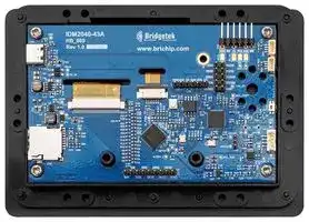
IDM2040-43A
TFT LCD, 4.3 ", 480 x 272 Pixels, Landscape, 5V
⚠️ Reference pricing provided. In case of supply shortages, we will connect you with our trusted procurement partners to ensure your project's continuity.
- Manufacturer: BRIDGETEK
- Product type: TFT LCD Displays
- SVHC: No SVHC (25-Jun-2025)
- VGA Size: -
- Resolution: 480 x 272 Pixels
- Module Size: 132.7mm x 93.5mm
- Touchscreen: Capacitive Touch
- Display Size: 4.3"
- Logic Voltage: 5V
- Product Range: -
- Display Pinout: 6 Way FPC
- Interface Type: I2C, RS-232, RS-485, SPI, UART
- Display Appearance: -
- Display Brightness: 450cd/m²
- Display Orientation: Landscape
- Operating Temperature Max: 70°C
- Operating Temperature Min: -20°C
| Delivery and price | |
|---|---|
| Units per pack | 10 |
| Price | 113.69 € |
| Current stock | 10+ |
| Lead time | 30 days |
Datasheet

**IDM2040-43A Datasheet Version 1.0**

YY = «* BridgetekBRIDGING

Document Reference No.: BRT_000420   Clearance No.: BRT#203

## **Bridgetek Pte Ltd IDM2040-43A**

## **Datasheet**

## **1 Introduction**

## **1.1 Features**

The IDM2040-43A is an intelligent display module featuring a 4.3 " 480 x272 resolution TFT LCD panel with capacitive touch panel. The module carries Bridgetek’s new embedded video engine controller BT883Q supported by a low-cost high-performance Raspberry PI RP2040 microcontroller. Apart from on board UART, I2C and SPI interfaces, users can also extend communication with two add-on accessories board to include RS232 and RS485 channels.

The input power source can either be from USB host/charger or UART-SIP connector.

With the use of a Raspberry Pi MCU RP2040, the IDM2040-43A module allows easy programming with various Circuit Python or Micro Python libraries.

- BT883Q new generation of EVE controller. Supports 4.3” 480x272 LCD with capacitive touch screen.

- On board audio power amplifier and audio connector for external speaker and audio line in.

- RP2040 MCU with 8 MB on-board flash memory programmable with Circuit Python (libraries provided).

- Type-C port for RP2040 USB DFU or debug. Micro-SD card socket.

- 2x Stemma QT (QWIIC) I2C peripheral sockets.

- SPI pin headers for Adafruit Wi-Fi module or other peripherals.

- 6-position header for mating with FTDI TTL cables

- RS232 transceiver adaptor (optional add on module).

- RS485 transceiver adaptor (optional add on module).

- Hardware reset button.

- RP2040 DFU button.

- Precision fitted bezel in black.

- CE/FCC/UKCA certified

Neither the whole nor any part of the information contained in, or the product described in this manual, may be adapted or reproduced in any material or electronic form without the prior written consent of the copyright holder. This product and its documentation are supplied on an as-is basis and no warranty as to their suitability for any particular purpose is either made or implied. Bridgetek Pte Ltd will not accept any claim for damages howsoever arising as a result of use or failure of this product. Your statutory rights are not affected. This product or any variant of it is not intended for use in any medical appliance, device or system in which the failure of the product might reasonably be expected to result in personal injury. This document provides preliminary information that may be subject to change without notice. No freedom to use patents or other intellectual property rights is implied by the publication of this document. Bridgetek Pte Ltd, 1 Tai Seng Avenue, #03-05, Singapore 4536464. Singapore Registered Company Number: 201542387H

Copyright © Bridgetek Pte Ltd

1

**IDM2040-43A Datasheet Version 1.0**

Document Reference No.: BRT_000420   Clearance No.: BRT#203

## **2 Ordering Information**

|**Part No.**|**Description**|
|---|---|
|IDM2040-43A|Intelligent DisplayModule 4.3-inch TFT LCD with CTP and bezel|
|IDM-RS232|UART to RS232 Interface Board|
|IDM-RS485|UART to RS485 Interface Board|


Copyright © Bridgetek Pte Ltd

2

**IDM2040-43A Datasheet Version 1.0**

Document Reference No.: BRT_000420   Clearance No.: BRT#203

## **Table of Contents**

**==> picture [393 x 583] intentionally omitted <==**

**----- Start of picture text -----**<br>
|||
|---|---|
|1|Introduction ........................................................ 1|
|1.1|Features ..................................................................... 1|
|2|Ordering Information .......................................... 2|
|3|Hardware Description ......................................... 5|
|3.1|IDM2040-43A Module ................................................ 5|
|3.2|Power supply ............................................................. 8|
|3.3|Microcontroller- Raspberry Pi RP2040 ........................ 8|
|3.4|Connectors & Buttons ................................................ 8|
|3.5|RS232/RS485 Daughter Boards ............................... 12|
|4|Specifications .................................................... 15|
|4.1|Electrical Specifications ........................................... 15|
|4.2|Display Specifications .............................................. 15|
|4.3|Optical Specifications ............................................... 15|
|5|Board Schematics ............................................. 17|
|6|Mechanical Dimensions ..................................... 20|
|6.1|IDM2040-43A PCBA Dimensions .............................. 20|
|6.2|IDM2040-43A Product Dimensions........................... 20|
|6.3|IDM-RS232 PCBA Dimensions ................................. 23|
|6.4|IDM-RS485 PCBA Dimensions .................................. 23|
|6.5|Assembling Bezel and Panel Mounting ..................... 24|
|7|Software Setup Information ............................. 26|
|7.1|C/C++ SDK Setup .................................................... 26|
|7.2|MicroPython SDK Setup ............................................ 26|
|7.3|Circuitpython SDK Setup .......................................... 27|
|7.4|Bridgetek CircuitPython SDK Setup .......................... 28|
|8|Disclaimer Notice: Use of Third-Party Software or|
|Websites ............................................................... 29|

**----- End of picture text -----**<br>


Copyright © Bridgetek Pte Ltd

3

**IDM2040-43A Datasheet Version 1.0**

|Document Reference No.: BRT_000420   Clearance No.: BRT#203<br>~~a~~|
|---|
|~~a~~|
|**9** **Contact Information .......................................... 30**|
|**Appendix A**<br>**References ....................................... 31**<br>~~_~~|
|**Document References ...................................................... 31**|
|**Acronyms and Abbreviations ........................................... 31**|
|**Appendix B**<br>**List of Tables & Figures.................... 32**<br>~~_~~|
|**List of Tables ................................................................... 32**|
|**List of Figures .................................................................. 32**|
|**Appendix C**<br>**Revision History ............................... 34**<br>~~-~~|


Copyright © Bridgetek Pte Ltd

4

**IDM2040-43A Datasheet Version 1.0**

Document Reference No.: BRT_000420   Clearance No.: BRT#203

## **3 Hardware Description**

## **3.1 IDM2040-43A Module**

The IDM2040-43A module consists of a 4.3 uw TFT LCD with 480x272 resolution and capacitive touch panel connected to HB_080 PCBA and encased in black plastic frame and bezel. The size of the module measures 132.7mm (L) x 93.5mm (H) x 26mm (W).

**Figure 1 - IDM2040-43A Module - Front View**

**Figure 2 - IDM2040-43A Module - Back View**

Copyright © Bridgetek Pte Ltd

5

**IDM2040-43A Datasheet Version 1.0**

Document Reference No.: BRT_000420   Clearance No.: BRT#203

**Figure 3 - IDM2040-43A PCBA - Front View**

**Figure 4 - IDM2040-43A PCBA Back View**

Copyright © Bridgetek Pte Ltd

6

**IDM2040-43A Datasheet Version 1.0**

Document Reference No.: BRT_000420   Clearance No.: BRT#203

## **Key Features:**

   - BT883Q EVE chip for graphics, touch and audio controller

- Raspberry Pi RP2040 microcontroller

- External Quad-SPI Flash with eXecute In Place (XIP)

- Type-C USB port for power and data (and for reprogramming Flash)

- One 40-pin 0.5mm pitch FPC connector for LCD interface

- One 6-pin 1mm pitch FPC connector for capacitive touch panel interface

- One 4-position 1.5mm JST male connector for 8-ohm 1W speaker

- Micro-SD card socket

- Two 4-position 1mm pitch JST male connectors (Stemma QT/ QWIIC) for I2C peripheral interface

- One 9-position 2.54mm Harwin male header for SPI peripheral interface

- One 6-position 2.54mm Harwin male header for mating with IDM-RS232 or IDMRS485 daughter boards.

- One 6-position 2.54mm Harwin male R/A header for mating with FTDI TTL cables (e.g., TTL-234X-5V)

- One 2x5 10-position 2.54mm Harwin male header for GPIO/PWM/ADC interface

- One 3-position 2mm Harwin male header for ARM Serial Wire Debug (SWD) port

- Bootsel button for entering USB device mode

- Hardware Reset Button

Copyright © Bridgetek Pte Ltd

7

**IDM2040-43A Datasheet Version 1.0**

Document Reference No.: BRT_000420   Clearance No.: BRT#203 ~~————e—e—ee— ss)...~~

## **3.2 Power supply**

There are 2 options for powering the IDM2040-43A module:

- 5V/0.5A USB Type-C connector - CN3.

- Or 5V/0.5A 1x6 position 2.54mm Harwin male header CN4/CN5.

Both power inputs are summed using Schottky diodes so the source with higher voltage will be use to power the system and back flow current will be blocked.  Power will then go to the DCDC Buck switching regulator to output the 3.3V supply for powering up the system.

## **3.3 Microcontroller- Raspberry Pi RP2040**

The Raspberry Pi RP2040 microcontroller unit used in the module has the following key features:

- Dual ARM Cortex-M0+ @ 133MHz

- 264kB on-chip SRAM in six independent banks

- Support 8MB of on-board Flash memory via dedicated QSPI bus

- Type-C USB port supporting USB2.0 Full-speed device function; reprogramming the Flash can be achieved by simply dragging and dropping a file onto the RP2040 which appears as a mass storage device.

- 26 multi-function 3.3V General Purpose I/O (GPIO) with 23 GPIOs being digital-only and 3 ADC-capable GPIOs.

- 3-pin ARM Serial Wire Debug (SWD) port; the standard Serial Wire Debug (SWD) port can reset the system and load and run code without any button presses as well as for debugging purpose.

For full details of the Raspberry Pi RP2040 MCU, please refer to the RP2040 Datasheet.

## **3.4 Connectors & Buttons**

**Figure 5 Connectors and buttons on IDM2040-43A**

Copyright © Bridgetek Pte Ltd

8

**IDM2040-43A Datasheet Version 1.0**

Document Reference No.: BRT_000420   Clearance No.: BRT#203

Connectors and buttons of IDM2040-43A are described in the following sections.

**Note:** All GP(IO)s stated below can also be configured as GPIO or PWM.

**CN1** is a 4-position connector header for audio output to 8 ohm/1W speaker and external audio line-in input.

**==> picture [346 x 58] intentionally omitted <==**

**----- Start of picture text -----**<br>
|||||
|---|---|---|---|
|Pin No.|Name|Type|Description|
|1|SP-|O|Audio output for speaker|
|2|SP+|O|Audio output for speaker|
|3|AGND|P|Analog Ground|
|4|AUD|I|Audio line-in input|

**----- End of picture text -----**<br>


**Table 1 CN1 Pinout**

**CN2 & CN7** are the Stemma QT/ QWIIC connectors for I2C interface with output power supply.

**==> picture [411 x 166] intentionally omitted <==**

**----- Start of picture text -----**<br>
||||||
|---|---|---|---|---|
|Pin No.|Name|Type|Description|Pin Configurable Function|
|1|GND|P|Ground|-|
|3.3V output power|
|2|VCC3V3|P|-|
|supply|
|CN2:|
|CN2:|GP20/ SPI0_RX/ UART1_TX/|
|I2C0_SDA|I2C Serial Bus,|I2C0_SDA|
|3|I/O|
|CN7:|Data Line|CN7:|
|I2C1_SDA|GP18/SPI0_SCK/|
|UART0_CTS/ I2C1_SDA|
|CN2:|
|CN2:|GP21/ SPI0_CSn/|
|I2C0_SCL|I2C Serial Bus,|UART1_RX/ I2C0_SCL|
|4|O|
|CN7:|Clock Line|CN7:|
|I2C1_SCL|GP19/SPI0_TX/|
|UART0_RTS/ I2C1_SCL|

**----- End of picture text -----**<br>


## **Table 2 CN2 & CN7 Pinout**

- **CN3** is a USB type C receptacle connector use for:

- i) powering up the module

- ii) communication between PC and RP2040 MCU,

- iii) device firmware updating and debugging.  The port communicates with PC via USB as a virtual com port.

**CN4** is use for communication with PC via MCU UART1 cum input power source.

**==> picture [383 x 95] intentionally omitted <==**

**----- Start of picture text -----**<br>
|||||
|---|---|---|---|
|Pin No.|Name|Type|Description|
|1|GND|P|Ground|
|2|NC|-|No connection|
|3|5V_IN|P|5V input power source|
|4|TTL_RXD|I|RP2040 UART1 communication receive port|
|5|TTL_TXD|O|RP2040 UART1 communication transmit port|
|6|NC|-|No connection|

**----- End of picture text -----**<br>


## **Table 3 CN4 Pinout**

**==> picture [342 x 58] intentionally omitted <==**

**----- Start of picture text -----**<br>
|||||
|---|---|---|---|
|CN5|is use for connection to RS232 and RS485 daughter boards.|
|Pin No.|Name|Type|Description|
|1|GND|P|Ground|
|2|VCC3V3|P|3.3V output power supply|
|3|5V_IN|P|5V input power source|

**----- End of picture text -----**<br>


Copyright © Bridgetek Pte Ltd

9

**IDM2040-43A Datasheet Version 1.0**

## «*“y BridgetekBRIDGINGTECHNOLOGY

Document Reference No.: BRT_000420   Clearance No.: BRT#203

|4|TTL_RXD|I|RP2040 UART1 communication receive port|
|---|---|---|---|
|5|TTL_TXD|O|RP2040 UART1 communication transmit port|
|6|DE|O|Driver output enable pin (RS485 interface)|


**Table 4 CN5 Pinout**

- **CN6** is a Micro SD card socket supporting single SPI communication mode and auto card detection.

**CN8** is a 3-position vertical pin header connector for

(SWD) port.

|**Pin No.**<br>**Name**<br>**Type**<br>**Description**<br>**Pin Configurable**<br>**Function**|**Pin No.**<br>**Name**<br>**Type**<br>**Description**<br>**Pin Configurable**<br>**Function**|**Pin No.**<br>**Name**<br>**Type**<br>**Description**<br>**Pin Configurable**<br>**Function**|**Pin No.**<br>**Name**<br>**Type**<br>**Description**<br>**Pin Configurable**<br>**Function**|**Pin No.**<br>**Name**<br>**Type**<br>**Description**<br>**Pin Configurable**<br>**Function**|
|---|---|---|---|---|
|1<br>SWCLK<br>I<br>Serial Wire Debug, Clock<br>SWCLK|||||
|2<br>GND<br>P<br>Ground<br>-|||||
|3|SWDIO|I/O|Serial Wire Debug, I/O|SWDIO|


**CN13** is a 9-position vertical pin header connector for SPI interface with output power supply. - The SPI bus signals are shared with Micro SD card except for the chip select signal.

|**Pin No.**<br>**Name**<br>**Type**<br>**Description**<br>**Pin Configurable**<br>**Function**|**Pin No.**<br>**Name**<br>**Type**<br>**Description**<br>**Pin Configurable**<br>**Function**|**Pin No.**<br>**Name**<br>**Type**<br>**Description**<br>**Pin Configurable**<br>**Function**|**Pin No.**<br>**Name**<br>**Type**<br>**Description**<br>**Pin Configurable**<br>**Function**|**Pin No.**<br>**Name**<br>**Type**<br>**Description**<br>**Pin Configurable**<br>**Function**|
|---|---|---|---|---|
|1<br>VCC3V3<br>P<br>3.3V output power supply<br>-|||||
|2<br>NC<br>-<br>No connection<br>-<br>~~eeGQ~~|||||
|3<br>GND<br>P<br>Ground<br>-<br>~~eeGQ~~|||||
|4<br>SPI1_SCK<br>O<br>SPI1 clock output<br>GP10/ SPI1_SCK/<br>UART1_CTS/<br>I2C1_SDA<br>~~eeGQ~~|||||
|5<br>SPI1_MISO<br>I<br>SPI master input, slave<br>output.<br>GP12/ SPI1_RX/<br>UART0_TX/ I2C0_SDA|||||
|6<br>SPI1_MOSI<br>O<br>SPI master output, slave<br>input.<br>GP11/ SPI1_TX/<br>UART1_RTS/<br>I2C1_SCL|||||
|7<br>SPI1_CS2#<br>O<br>SPI Chip Select output for<br>external SPI peripheral<br>device, active low. On board<br>-up to 3.3V.<br>GP22/ SPI0_SCK/<br>UART1_CTS/<br>I2C1_SDA|||||
|8<br>BUSY<br>I<br>Reserve for AdafruitAirLift<br>Breakout Wi-Fi module<br>GP14/ SPI1_SCK/<br>UART0_CTS/<br>I2C1_SDA|||||
|9|RESET#|O|Reserve for AdafruitAirLift<br>Breakout Wi-Fi module|GP15/ SPI1_TX/<br>UART0_RTS/<br>I2C1_SCL|


**Table 6 CN13 Pinout**

Copyright © Bridgetek Pte Ltd

10

**IDM2040-43A Datasheet Version 1.0**

Document Reference No.: BRT_000420   Clearance No.: BRT#203

~~e~~ **CN14** is a 2x5, 10-position vertical pin header use for GPIO/ADC/PWM interface with output power supply.

|**Pin No.**|**Name**|**Type**|**Description**|**Pin Configurable Function**|
|---|---|---|---|---|
|1|GPIO0|I/O|GPIO|GP0/ SPI0_RX/ UART0_TX/ I2C0_SDA|
|2|GND|P|Ground|-|
|3|GPIO1|I/O|GPIO|GP1/ SPI0_CSn/ UART0_RX/<br>I2C0_SCL|
|4|GPIO29_ADC3|I/O|GPIO|GP29/ SPI1_CSn/ UART0_RX/<br>I2C0_SCL/ ADC|
|5|GPIO16|I/O|GPIO|GP16/ SPI0_RX/ UART0_TX/<br>I2C0_SDA|
|6|GPIO26_ADC0|I/O|GPIO|GP26/ SPI1_SCK/ UART1_CTS/<br>I2C1_SDA/ ADC|
|7|GPIO17|I/O|GPIO|GP17/ SPI0_CSn/ UART0_RX/<br>I2C0_SCL|
|8|VCC3V3|P|3.3V output<br>power supply|-|
|9|GND|P|Ground|-|
|10|GPIO23|I/O|GPIO|GP23/ SPI0_TX/ UART1_RTS/<br>I2C1_SCL|


## **Table 7 CN14 Pinout**

- ~~e~~ **SW1** is the BOOTSEL button to put RP2040 MCU into programming mode to program firmware into the 8MB flash memory connected to QSPI bus.

   - **SW2** is hardware reset button to reset RP2040 MCU.

- e

Copyright © Bridgetek Pte Ltd

11

**IDM2040-43A Datasheet Version 1.0**

Document Reference No.: BRT_000420   Clearance No.: BRT#203

## **3.5 RS232/RS485 Daughter Boards**

## **3.5.1 RS232 Daughter Board**

RS232 daughter board is an interface board for IDM2040-43A that translates the UART1 signal from MCU to RS232 communication channel.  The diagram below shows the correct orientation of inserting the RS232 daughter board onto main PCBA.  Snap lock standoffs will be provided for further locking security.

**Figure 6 IDM-RS232 Daughter Board Mounting Orientation**

## **3.5.2 Connectors on RS232 Daughter Board**

**Figure 7 Connectors on IDM-RS232**

Copyright © Bridgetek Pte Ltd

12

**IDM2040-43A Datasheet Version 1.0**

## YY = «* BridgetekBRIDGING TECHNOLOGY

Document Reference No.: BRT_000420   Clearance No.: BRT#203

**CN10** is a 4-position terminal block use for RS232 communication cum input power source.

|**Pin No.**<br>**Name**<br>**Type**<br>**Description**|**Pin No.**<br>**Name**<br>**Type**<br>**Description**|**Pin No.**<br>**Name**<br>**Type**<br>**Description**|**Pin No.**<br>**Name**<br>**Type**<br>**Description**|
|---|---|---|---|
|1<br>5V<br>P<br>5V input power source||||
|2<br>RX_IN<br>I<br>RS232 communication receive port||||
|3<br>TX_OUT<br>O<br>RS232 communication transmit port||||
|4|GND|P|Ground|


**Table 8 - CN10 Pinout**

**CN9** is a 6-position housing use for connection with IDM2040-43A CN5 header connected

|~~toMCU’sUART1port~~|~~toMCU’sUART1port~~|~~portand~~|~~portand~~|~~inputpower~~|~~inputpower~~|~~powersource.~~|~~source.~~|
|---|---|---|---|---|---|---|---|
|**Pin No.**<br>**Name**<br>**Type**<br>**Description**<br>~~to MCU’s UART1 port and~~<br>~~input power source.~~||||||||
|1<br>GND<br>P<br>Ground||||||||
|2<br>VCC3V3<br>P<br>3.3V input power source||||||||
|3<br>5V_IN<br>P<br>5V output power supply||||||||
|4<br>RXD<br>O<br>To RP2040 UART1 communication receive port||||||||
|5<br>TXD<br>I<br>To RP2040 UART1 communication transmit port||||||||
|6|NC||-||No connection|||


**Table 9 - CN9 Pinout**

## **3.5.3 RS485 Daughter Board**

RS485 daughter board is an interface board for IDM2040-43A that translates the UART1 signal from MCU to RS485 communication channel.  The diagram below shows the correct orientation of inserting the RS485 daughter board onto the main PCBA.  Snap lock standoffs will be provided for further locking security.

**Figure 8 IDM-RS485 Daughter Board Mounting Orientation**

Copyright © Bridgetek Pte Ltd

13

**IDM2040-43A Datasheet Version 1.0**

Document Reference No.: BRT_000420   Clearance No.: BRT#203

## **3.5.4 Connectors on RS485 Daughter Board**

**Figure 9 - Connectors on IDM-RS485**

**CN11** is a 4-position terminal block use for RS485 communication cum input power source.

|**Pin No.**<br>**Name**<br>**Type**<br>**Description**|**Pin No.**<br>**Name**<br>**Type**<br>**Description**|**Pin No.**<br>**Name**<br>**Type**<br>**Description**|**Pin No.**<br>**Name**<br>**Type**<br>**Description**|
|---|---|---|---|
|1<br>5V<br>P<br>5V input power source||||
|2<br>B<br>I/O<br>Inverting driver/receiver||||
|3<br>A<br>I/O<br>Noninverting driver/receiver||||
|4|GND|P|Ground|


**Table 10 - CN11 Pinout**

**CN12** is a 6-position housing use for connection with IDM2040-43A CN5 header

|~~connectedtoMCU’sUART1port~~|~~connectedtoMCU’sUART1port~~|~~connectedtoMCU’sUART1port~~|~~portandinput~~|~~portandinput~~|~~inputpower~~|~~powersource.~~|~~source.~~|
|---|---|---|---|---|---|---|---|
|**Pin No.**<br>**Name**<br>**Type**<br>**Description**<br>~~connected to MCU’s UART1 port and input power source.~~||||||||
|1<br>GND<br>P<br>Ground||||||||
|2<br>VCC3V3<br>P<br>3.3V input power source||||||||
|3<br>5V_IN<br>P<br>5V output power supply||||||||
|4<br>RX<br>O<br>To RP2040 UART1 communication receive port||||||||
|5<br>TX<br>I<br>To RP2040 UART1 communication transmit port||||||||
|6|TX_EN|-||Driver output enable pin||||


**Table 11 - CN12 Pinout.**

**CN15** is a 2x1 header when shorted with shunt will provide 120-ohm termination resistance across port A and B. This is to meet RS485 termination requirements if the module is the first or last device in a multi-drop RS485 System.

Copyright © Bridgetek Pte Ltd

14

**IDM2040-43A Datasheet Version 1.0**

@“y* BridgetekBRIDGING=

Document Reference No.: BRT_000420   Clearance No.: BRT#203

## **4 Specifications**

## **4.1 Electrical Specifications**

|**Parameter**<br>**Description**<br>**Minimum**<br>**Typical**<br>**Maximum**<br>**Units**<br>**Notes**<br>~~eS~~|**Parameter**<br>**Description**<br>**Minimum**<br>**Typical**<br>**Maximum**<br>**Units**<br>**Notes**<br>~~eS~~|**Parameter**<br>**Description**<br>**Minimum**<br>**Typical**<br>**Maximum**<br>**Units**<br>**Notes**<br>~~eS~~|**Parameter**<br>**Description**<br>**Minimum**<br>**Typical**<br>**Maximum**<br>**Units**<br>**Notes**<br>~~eS~~|**Parameter**<br>**Description**<br>**Minimum**<br>**Typical**<br>**Maximum**<br>**Units**<br>**Notes**<br>~~eS~~|**Parameter**<br>**Description**<br>**Minimum**<br>**Typical**<br>**Maximum**<br>**Units**<br>**Notes**<br>~~eS~~|**Parameter**<br>**Description**<br>**Minimum**<br>**Typical**<br>**Maximum**<br>**Units**<br>**Notes**<br>~~eS~~|
|---|---|---|---|---|---|---|
|VBUS<br>supply voltage<br>4.5<br>5.0<br>5.5<br>V<br>CN3<br>~~eS~~<br>~~eS~~|||||||
|+5V<br>supply voltage<br>4.5<br>5.0<br>5.5<br>V<br>CN4<br>~~eS~~<br>~~eS~~|||||||
|+5V<br>supply voltage<br>4.5<br>5.0<br>5.5<br>V<br>CN5<br>~~eS~~|||||||
|Icc1_3.3V<br>VCC=3.3V<br>operating<br>current<br>-<br>225<br>-<br>mA<br>With LCD<br>and<br>Backlight<br>LED on|||||||
|Icc2_3.3V<br>VCC=3.3V<br>operating<br>current<br>-<br>260<br>-<br>mA<br>With 8 OHM<br>speaker<br>connected|||||||
|Voh<br>Output Voltage<br>High<br>2.4<br>-<br>-<br>V|||||||
|Vol<br>Output Voltage<br>Low<br>-<br>-<br>0.4<br>V|||||||
|Vih<br>Input High<br>Voltage<br>2.0<br>-<br>-<br>V|||||||
|Vil<br>Input Low<br>Voltage<br>-<br>-<br>0.8<br>V<br>~~aa~~<br>~~ee~~<br>~~eeee~~|||||||
|T<br>~~a~~|Operating<br>temperature<br>~~a~~|-20<br>~~ee~~|-<br>~~ee~~|+70<br>~~ee~~|~~ee~~|~~ee~~|


## **4.2 Display Specifications**

|**Item**<br>**Spec**<br>**Units**<br>**Notes**|**Item**<br>**Spec**<br>**Units**<br>**Notes**|**Item**<br>**Spec**<br>**Units**<br>**Notes**|**Item**<br>**Spec**<br>**Units**<br>**Notes**|
|---|---|---|---|
|LCD Type<br>TFT<br>-||||
|Display Colours<br>16.7M<br>-||||
|Display active area<br>95.04(H)*53.86(V)<br>mm<br>4.3-inch diagonal||||
|Number of Pixels<br>480*272<br>dots||||
|Backlight<br>5X2 white LEDs<br>-||||
|Touchscreen|5-fingercapacitive touch|-||


**Table 13 LCD and Touch Information**

## **4.3 Optical Specifications**

|**4.3 Optical Specifications**||
|---|---|
|**Item**<br>**Symbol**<br>**Condition**<br>**Min.**<br>**Typ.**<br>**Max.**<br>**Unit**<br>**Note**<br>Brightness<br>Bp<br>=0°<br>=0°<br>-<br>450<br>-<br>Cd/m2<br>1<br>Uniformity<br>Bp<br>75<br>-<br>-<br>%<br>1,2<br>3:00<br>-<br>65<br>-<br>~~pf5 *§~~||
|Viewing<br>Angle<br>Deg<br>3<br>6:00<br>-<br>55<br>-<br>9:00<br>-<br>65<br>-<br>~~—~~<br>~~—~~||
|12:00<br>-<br>65<br>-<br>Contrast<br>Ratio<br>Cr<br>=0°<br>350<br>500<br>-<br>4<br>Response<br>Tr<br>-<br>10<br>-<br>ms<br>~~|~~<br>~~|)~~<br>~~|~~<br>~~|ht~~<br>~~Hf _}* |}~~<br>~~}~~<br>~~|~~<br>~~| _~~||
|Copyright © Bridgetek Pte Ltd<br>15||


**IDM2040-43A Datasheet Version 1.0**

## @oY* BridgetekBRIDGING=

Document Reference No.: BRT_000420   Clearance No.: BRT#203

**==> picture [402 x 133] intentionally omitted <==**

**----- Start of picture text -----**<br>
Time  Tf  =0°  - 10  - ms  5<br>| ti“(tests ee ee ee ee<br>Color of CIE  x  0.28  -<br>Coordinate  W<br>y  0.33  -<br>| fF x  SJ 0.51  -<br>- R  || y  =0°  -0.05 | 0.34  +0.05 | -<br>x  =0° 0.31  -<br>PoE G  y  | |— 0.56  |FS - 1,6<br>— ° —— =  -=<br>x  0.15  -<br>—— B  y J 0.14  a -<br>NTSC  S  50  60  -  %<br>a Ratio<br>**----- End of picture text -----**<br>


**Table 14 Optical Specifications**

**Note 1:** The parameter is slightly changed by temperature, driving voltage and material

**Note 2:** The data are measured after LEDs are turned on for 15 minutes. LCM displays full white. The brightness is the average value of 9 measured spots. Measurement equipment BM ~~7~~ (@ 5mm)

Measuring condition:

- Measuring surroundings: Dark room.

- Measuring temperature: Ta=25 °C .

- Adjust operating voltage to get optimum contrast at the center of the display.

Measured value at the center point of LCD panel after more than 15 minutes while backlight turned on.

Copyright © Bridgetek Pte Ltd

16

## <+»+ Bridgetek= **IDM2040-43A Datasheet Version 1.0** * g ON BRIDGING TECHNOLOGY Document Reference No.: BRT_000420   Clearance No.: BRT#203 ~~ee ————e—e—ee— ss)...~~ **5 Board Schematics**

## **Figure 10 - IDM2040-43A Block Diagram**

**==> picture [153 x 9] intentionally omitted <==**

**----- Start of picture text -----**<br>
Figure 11 - RP2040 MCU Circuit<br>**----- End of picture text -----**<br>


**==> picture [133 x 9] intentionally omitted <==**

**----- Start of picture text -----**<br>
Copyright © Bridgetek Pte Ltd<br>**----- End of picture text -----**<br>


17

**IDM2040-43A Datasheet Version 1.0**

**==> picture [441 x 16] intentionally omitted <==**

**----- Start of picture text -----**<br>
°<br>Document Reference No.: BRT_000420   Clearance No.: BRT#203<br>OO<br>**----- End of picture text -----**<br>


**Figure 12 BT883Q and LCD Circuit**

**Figure 13 Power and Audio Circuit**

Copyright © Bridgetek Pte Ltd

18

**IDM2040-43A Datasheet Version 1.0**

Document Reference No.: BRT_000420   Clearance No.: BRT#203

**Figure 14 RS232 Daughter Board Schematic**

**Figure 15 - RS485 Daughter Board Schematic**

Copyright © Bridgetek Pte Ltd

19

**IDM2040-43A Datasheet Version 1.0**

Document Reference No.: BRT_000420   Clearance No.: BRT#203

## **6 Mechanical Dimensions**

## **6.1 IDM2040-43A PCBA Dimensions**

**Figure 16 IDM2040-43A PCBA Dimensions (Top View)**

## **6.2 IDM2040-43A Product Dimensions**

**Figure 17 - IDM2040-43A Product Dimensions (Front View)**

Copyright © Bridgetek Pte Ltd

20

**IDM2040-43A Datasheet Version 1.0**

Document Reference No.: BRT_000420   Clearance No.: BRT#203 ~~————e—e—ee— ss)...~~

**Figure 18 - IDM2040-43A Product Dimensions (Side View)**

**Figure 19 - IDM2040 Product Dimensions (Back View)**

Copyright © Bridgetek Pte Ltd

21

**IDM2040-43A Datasheet Version 1.0**

Document Reference No.: BRT_000420   Clearance No.: BRT#203

**Figure 20 - Mating height between IDM2040-43A and IDM-RS232**

Copyright © Bridgetek Pte Ltd

22

**IDM2040-43A Datasheet Version 1.0**

Document Reference No.: BRT_000420   Clearance No.: BRT#203

## **6.3 IDM-RS232 PCBA Dimensions**

**Figure 21 - IDM-RS232 PCBA dimensions**

## **6.4 IDM-RS485 PCBA Dimensions**

**Figure 22 - IDM-RS485 PCBA dimensions**

Copyright © Bridgetek Pte Ltd

23

**IDM2040-43A Datasheet Version 1.0**

Document Reference No.: BRT_000420   Clearance No.: BRT#203

## **6.5 Assembling Bezel and Panel Mounting**

**Figure 23 - IDM2040-43A Panel Mount (Front view)**

**Figure 24 - IDM2040-43A Panel Mount (Rear View)**

Copyright © Bridgetek Pte Ltd

24

**IDM2040-43A Datasheet Version 1.0**

Document Reference No.: BRT_000420   Clearance No.: BRT#203

**Figure 25 - IDM2040-43A Panel Mount Dimensions**

Copyright © Bridgetek Pte Ltd

25

**IDM2040-43A Datasheet Version 1.0**

Document Reference No.: BRT_000420   Clearance No.: BRT#203

## «RY,* BridgetekBRIDGINGa TECHNOLOGY

## **7 Software Setup Information**

- The RP2040 microcontroller can be programmed using C/C++, MicroPython or CircuitPython.

## **7.1 C/C++ SDK Setup**

- For C/C++ development, the following programs need to be installed.

Python 3.x ARM GCC compiler CMake Build Tools for Visual Studio 2019 (C++ build tools only) Visual Studio Code pico-sdk tools

- It is recommended to download one package of all the above tools from here to install them.

- Raspberry Pi PICO/RP2040 C/C++ SDK document can be downloaded here.

- Raspberry Pi PICO/RP2040 C/C++ examples can be downloaded here.

- Raspberry Pi PICO/RP2040 C/C++ API Document is here.

- Download and install latest EVE Screen Designer (ESD) from here.

- Open ESD tools and run any example provided in the application.

- User needs to change the build target to IDM2040-43A via the toolbar button. User needs to build code to generate UF2 file.

- Push and hold SW1 BOOTSEL button on board while powering up the module by connecting CN3 to the computer using USB type C cable. Release BOOTSEL once the drive RPI-RP2 appears, drag and drop the UF2 file into the RPI-RP2 drive.

## **7.2 MicroPython SDK Setup**

- Download the MicroPython UF2 file from MicroPython.

- Push and hold SW1 BOOTSEL button on the board, then connect your computer using a type C USB cable. Release BOOTSEL once the drive RPI-RP2 appears on your computer

- Drag and drop the UF2 file into the RPI-RP2 drive. The RP2040 will reboot and will now run MicroPython.

- Download and install Thonny for your computer.

- Connect the board to your computer and in Thonny go to Tools>Options and click on the interpreter tab. From the interpreter dropdown list select MicroPython (Raspberry Pi PICO). Choose port "USB Serial Device (COMX)” . Figure 20 shows the Micropython with Thonny in ready status.

Copyright © Bridgetek Pte Ltd

26

**IDM2040-43A Datasheet Version 1.0**

Document Reference No.: BRT_000420   Clearance No.: BRT#203

**Figure 26 MicroPython with Thonny in READY status**

- Raspberry Pi PICO/RP2040 MicroPython SDK document can be downloaded from ~~—__~~ here.

- Raspberry Pi PICO MicroPython examples can be downloaded from ~~——~~ here.

- Blink D2A example code is

_from machine import Pin import utime led = Pin(25,Pin.OUT) while True: led.value(1) utime.sleep(1) led.value(0) utime.sleep(1)_

## **7.3 Circuitpython SDK Setup**

- Download the CircuitPython UF2 file from ~~a~~ CircuitPython.

- Push and hold SW1 BOOTSEL button on the board, then connect your computer using a type C USB cable. Release BootSEL once the drive RPI-RP2 appears on the computer.

- Drag and drop the UF2 file into the RPI-RP2 drive. The RP2040 will reboot and the drive CIRCUITPY will appear.

- Download and install —_____ Thonny  or — Mu for your computer, recommend to install Mu editor for CircuitPython application.

- Connect the board to your computer and Run Mu, select RP2040, the MU with CircuitPython is ready to use.

Copyright © Bridgetek Pte Ltd

27

**IDM2040-43A Datasheet Version 1.0**

Document Reference No.: BRT_000420   Clearance No.: BRT#203

**Figure 27 Install Mu Editor**

- Blink D2A example code is

_**import** time_ _**import** board_ _**import** digitalio led = digitalio.DigitalInOut(board.GP25) led.direction = digitalio.Direction.OUTPUT_

_**while True:** led.value =_ _**True** time.sleep(1) led.value =_ _**False** time.sleep(1)_

## **7.4 Bridgetek CircuitPython SDK Setup**

- Below is the link which provides the sample code & libraries to run the EVE module in CircuitPython.

   - pico-bteve github link

   - Visit BRT’s website at https://brtchip.com/eve/ for more information regarding the EVE module & its toolchain.

Copyright © Bridgetek Pte Ltd

28

**IDM2040-43A Datasheet Version 1.0**

Document Reference No.: BRT_000420   Clearance No.: BRT#203

## **8 Disclaimer Notice: Use of Third-Party Software or Websites**

We may recommend use of software or web sites that are owned or operated by other companies. We offer or facilitate this recommendation by hyperlinks or other methods to aid your access to the third-party resource. While we endeavour to direct you to helpful, trustworthy resources, we cannot endorse, approve, or guarantee software, information, products, or services provided by or at a third-party resource or track changes in the resource. Thus, we are not responsible for the content or accuracy of any third-party resource or for any loss or damage of any sort resulting from the use of, or for any failure of, products or services provided at or from a third-party resource.

We recommend these resources on an “as is” basis. When you use a third-party resource, you will be subject to its terms and licenses and no longer be protected by our privacy policy or security practices, which may differ from the third policy or practices or other terms. You should familiarize yourself with any license or use terms of, and the privacy policy and security practices of, the thirdparty resource, which will govern your use of that resource.

Copyright © Bridgetek Pte Ltd

29

**IDM2040-43A Datasheet Version 1.0**

Document Reference No.: BRT_000420   Clearance No.: BRT#203

## **9 Contact Information**

Refer to https://brtchip.com/contact-us/ for contact information

## **Distributor and Sales Representatives**

Please visit the Sales Network page of the Bridgetek Web site for the contact details of our distributor(s) and sales representative(s) in your country.

System and equipment manufacturers and designers are responsible to ensure that their systems, and any Bridgetek Pte Ltd (BRTChip) devices incorporated in their systems, meet all applicable safety, regulatory and system-level performance requirements. All application-related information in this document (including application descriptions, suggested Bridgetek devices and other materials) is provided for reference only. While Bridgetek has taken care to assure it is accurate, this information is subject to customer confirmation, and Bridgetek disclaims all liability for system designs and for any applications assistance provided by Bridgetek. Use of Bridgetek devices in life support and/or safety applications is entirely at the user’s risk, and the user agrees to defend, indemnify and hold harmless Bridgetek from any and all damages, claims, suits or expense resulting from such use. This document is subject to change without notice. No freedom to use patents or other intellectual property rights is implied by the publication of this document. Neither the whole nor any part of the information contained in, or the product described in this document, may be adapted or reproduced in any material or electronic form without the prior written consent of the copyright holder. Bridgetek Pte Ltd, 1 Tai Seng Avenue, #03-05, Singapore 4536464. Singapore Registered Company Number: 201542387H.

Copyright © Bridgetek Pte Ltd

30

**IDM2040-43A Datasheet Version 1.0**

Document Reference No.: BRT_000420   Clearance No.: BRT#203

## **Appendix A References**

## **Document References**

BT883 Datasheet

RP2040 Datasheet

## **Acronyms and Abbreviations**

|**Terms**<br>**Description**|**Terms**<br>**Description**|
|---|---|
|SIP<br>Single Inline Package||
|DFU<br>Device Firmware Update||
|PCBA<br>Printed Circuit Board Assembled||
|EVE<br>Embedded Video Engine||
|I2C<br>Inter-Integrated Circuit||
|MCU<br>Micro Controller Unit||
|PWM<br>Pulse Width Modulation||
|SPI<br>Serial Peripheral Interface||
|SWD<br>Serial Wire Debug||
|TTL<br>Transistor-transistor Logic||
|USB<br>Universal Serial Bus||
|UART|Universal Asynchronous Receiver-Transmitter|


Copyright © Bridgetek Pte Ltd

31

**IDM2040-43A Datasheet Version 1.0**

Document Reference No.: BRT_000420   Clearance No.: BRT#203

## **Appendix B List of Tables & Figures**

## **List of Tables**

|Table 1|Table 1|CN1 Pinout ................................................................................................ 9|
|---|---|---|
|Table 2|Table 2|CN2 & CN7 Pinout....................................................................................... 9|
|Table 3|Table 3|CN4 Pinout ................................................................................................ 9|
|Table 4|Table 4|CN5 Pinout .............................................................................................. 10|
|Table 5|Table 5|CN8 Pinout .............................................................................................. 10|
|Table 6|Table 6|CN13 Pinout ............................................................................................ 10|
|Table 7|Table 7|CN14 Pinout ............................................................................................ 11|
|Table 8 - CN10 Pinout ............................................................................................. 13|Table 8 - CN10 Pinout ............................................................................................. 13|Table 8 - CN10 Pinout ............................................................................................. 13|
|Table 9 - CN9 Pinout ............................................................................................... 13|Table 9 - CN9 Pinout ............................................................................................... 13|Table 9 - CN9 Pinout ............................................................................................... 13|
|Table 10 - CN11 Pinout ........................................................................................... 14|Table 10 - CN11 Pinout ........................................................................................... 14|Table 10 - CN11 Pinout ........................................................................................... 14|
|Table 11 - CN12 Pinout. .......................................................................................... 14|Table 11 - CN12 Pinout. .......................................................................................... 14|Table 11 - CN12 Pinout. .......................................................................................... 14|
|Table 12|Table 12|Table 12<br>Operating Voltage and Current ................................................................. 15|
|Table 13|Table 13|Table 13<br>LCD and Touch Information ..................................................................... 15|
|Table 14|Table 14|Table 14<br>Optical Specifications .............................................................................. 16|


## **List of Figures**

|**List of Figures**|**List of Figures**|**List of Figures**|
|---|---|---|
|Figure 1 - IDM2040-43A Module - Front View ............................................................... 5|Figure 1 - IDM2040-43A Module - Front View ............................................................... 5|Figure 1 - IDM2040-43A Module - Front View ............................................................... 5|
|Figure 2 - IDM2040-43A Module - Back View ............................................................... 5|Figure 2 - IDM2040-43A Module - Back View ............................................................... 5|Figure 2 - IDM2040-43A Module - Back View ............................................................... 5|
|Figure 3 - IDM2040-43A PCBA - Front View ................................................................. 6|Figure 3 - IDM2040-43A PCBA - Front View ................................................................. 6|Figure 3 - IDM2040-43A PCBA - Front View ................................................................. 6|
|Figure 4 - IDM2040-43A PCBA|Figure 4 - IDM2040-43A PCBA|Figure 4 - IDM2040-43A PCBA<br>Back View ................................................................. 6|
|Figure 5|Figure 5|Connectors and buttons on IDM2040-43A .................................................... 8|
|Figure 6|Figure 6|IDM-RS232 Daughter Board Mounting Orientation ....................................... 12|
|Figure 7|Figure 7|Connectors on IDM-RS232 ....................................................................... 12|
|Figure 8|Figure 8|IDM-RS485 Daughter Board Mounting Orientation ....................................... 13|
|Figure 9 - Connectors on IDM-RS485 ........................................................................ 14|Figure 9 - Connectors on IDM-RS485 ........................................................................ 14|Figure 9 - Connectors on IDM-RS485 ........................................................................ 14|
|Figure 10 - IDM2040-43A Block Diagram ................................................................... 17|Figure 10 - IDM2040-43A Block Diagram ................................................................... 17|Figure 10 - IDM2040-43A Block Diagram ................................................................... 17|
|Figure 11 - RP2040 MCU Circuit ............................................................................... 17|Figure 11 - RP2040 MCU Circuit ............................................................................... 17|Figure 11 - RP2040 MCU Circuit ............................................................................... 17|
|Figure 12|Figure 12|Figure 12<br>BT883Q and LCD Circuit ......................................................................... 18|
|Figure 13|Figure 13|Figure 13<br>Power and Audio Circuit ......................................................................... 18|
|Figure 14|Figure 14|Figure 14<br>RS232 Daughter Board Schematic ........................................................... 19|
|Figure 15 - RS485 Daughter Board Schematic ............................................................ 19|Figure 15 - RS485 Daughter Board Schematic ............................................................ 19|Figure 15 - RS485 Daughter Board Schematic ............................................................ 19|
|Figure 16|Figure 16|Figure 16<br>IDM2040-43A PCBA Dimensions (Top View) .............................................. 20|
|Figure 17 - IDM2040-43A Product Dimensions (Front View) ......................................... 20|Figure 17 - IDM2040-43A Product Dimensions (Front View) ......................................... 20|Figure 17 - IDM2040-43A Product Dimensions (Front View) ......................................... 20|
|Figure 18 - IDM2040-43A Product Dimensions (Side View) .......................................... 21|Figure 18 - IDM2040-43A Product Dimensions (Side View) .......................................... 21|Figure 18 - IDM2040-43A Product Dimensions (Side View) .......................................... 21|
|Figure 19 - IDM2040 Product Dimensions (Back View) ................................................ 21|Figure 19 - IDM2040 Product Dimensions (Back View) ................................................ 21|Figure 19 - IDM2040 Product Dimensions (Back View) ................................................ 21|
|Figure 20 - Mating height between IDM2040-43A and IDM-RS232 ................................ 22|Figure 20 - Mating height between IDM2040-43A and IDM-RS232 ................................ 22|Figure 20 - Mating height between IDM2040-43A and IDM-RS232 ................................ 22|


Copyright © Bridgetek Pte Ltd 32

**IDM2040-43A Datasheet Version 1.0**

|Document Reference No.: BRT_000420   Clearance No.: BRT#203<br>~~a~~|
|---|
|~~a~~|
|Figure 21 - IDM-RS232 PCBA dimensions .................................................................. 23|
|Figure 22 - IDM-RS485 PCBA dimensions .................................................................. 23|
|Figure 23 - IDM2040-43A Panel Mount (Front view) .................................................... 24|
|Figure 24 - IDM2040-43A Panel Mount (Rear View) .................................................... 24|
|Figure 25 - IDM2040-43A Panel Mount Dimensions ..................................................... 25|
|Figure 26<br>MicroPython with Thonny in READY status ................................................ 27|
|Figure 27<br>Install Mu Editor .................................................................................... 28|


Copyright © Bridgetek Pte Ltd

33

**IDM2040-43A Datasheet Version 1.0**

Document Reference No.: BRT_000420   Clearance No.: BRT#203

## **Appendix C Revision History**

Document Title: IDM2040-43A Datasheet Document Reference No.: BRT_000420 Clearance No.: BRT#203 - Product Page: https://brtchip.com/product category/products/ Document Feedback: Send Feedback

|**Revision**|**Changes**|**Date**|
|---|---|---|
|Version 1.0|Initial Release|13-09-2023|


Copyright © Bridgetek Pte Ltd

34
Updated at April 23, 2026
About Novapart
Novapart is a B2B electronic component broker specialising in stock shortages and cost reduction. We source hard-to-find parts and identify compliant alternatives across a catalogue of 410,000+ components from 500+ manufacturers.
Learn more →Stock Shortage Specialist
When a component is unavailable, discontinued or has an unacceptable lead time, we tap into our network of vetted European and Asian distributors to source what you need — without compromising on quality or traceability.
Request a quote →Compliant Alternatives
We identify pin-to-pin, electrically equivalent substitutes that meet the same certifications (RoHS, AEC-Q100, REACH) as your original specification — validated against datasheets, not just part numbers. Often at a lower cost.
BOM Analysis service →