
Image not available
Illustrative purposes only

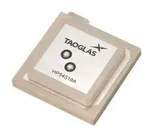
HP54510A
RF Antenna, 1.593 to 1.61GHz, GPS/GNSS/Glonass/Galileo/BeiDou/IRNSS/QZSS/SBAS/L-Band, 4.15dBi
⚠️ Reference pricing provided. In case of supply shortages, we will connect you with our trusted procurement partners to ensure your project's continuity.
- Manufacturer: TAOGLAS
- Product type:
- Gain: 4.15dBi
- SVHC: To Be Advised
- VSWR: -
- Input Power: -
- Antenna Type: GPS / GNSS / Glonass / Galileo / BeiDou / IRNSS / QZSS / SBAS / L-Band
- Frequency Max: 1.61GHz
- Frequency Min: 1.593GHz
- Product Range: -
- Input Impedance: 50ohm
- Antenna Mounting: PCB
- Antenna Polarisation: Right Hand Circular
| Delivery and price | |
|---|---|
| Units per pack | 250 |
| Price | 6.95 € |
| Current stock | 10+ |
| Lead time | 30 days |
Datasheet

**==> picture [37 x 19] intentionally omitted <==**

**----- Start of picture text -----**<br>
hn, D<br>**----- End of picture text -----**<br>


## 5 Qd Qd Cc Y) (© +) (O C)

|1.|Introduction|3|
|---|---|---|
|2.|Specifications|4|
|3.|Antenna Characteristics|6|
|4.|Radiation Patterns|9|
|5.|Antenna Integration Guide|15|
|6.|Mechanical Drawing|22|
|7.|Packaging|23|
||Changelog|24|


Taoglas makes no warranties based on the accuracy or completeness of the contents of this document and reserves the right to make changes to specifications and product descriptions at any time without notice. Taoglas reserves all rights to this document and the information contained herein.

Reproduction, use or disclosure to third parties without express permission is strictly prohibited.

www.taoglas.com

SPE-23-8-224-A

2

## 1. Introduction

The Taoglas HP54510A is a high performance, multi-band passive GNSS antenna that has been carefully designed to provide fantastic positional accuracy on the L1/L5 GNSS spectrum. It covers GPS/QZSS L1/L5, GLONASS G1, Galileo E1/E5a, BeiDou B1/B2a, as well as SBAS (WAAS/EGNOS/GAGAN/SDCM/SNAS) as well as the L Band at 1525MHz.

Correct implementation of the HP54510A allows the user to achieve higher location accuracy, as well as stability of position tracking in urban environments. The stacked patch construction has excellent performance across the full bandwidth of the antenna.

Its design has an even gain across the hemisphere, giving excellent axial ratio, which in turn makes it extremely resilient to multipath rejection and provides excellent phase centre stability to ensure a location is correctly established in a navigation system.

Typical applications that benefit from high precision capabilities include:

- Autonomous Driving

- Precision Agriculture

- Telematics & Container / Asset Tracking

- Timing Accuracy Synchronization

- Precision Positioning for Robotics

The HP54510A is the latest embedded addition to Taoglas’ product portfolio of high precision GNSS antennas. When used on the base and/or the rover as part of an RTK configuration, the HP54510A can achieve genuine cmlevel accuracy with proven results.

Full integration guidelines are contained in Section 7 of this datasheet including the Taoglas HC125.A hybrid coupler that will be required for use for dual pin feed patch integrations.

Contact your regional Taoglas Customer Services team for more information on any of the products listed above or for support regarding integration.

www.taoglas.com 3

SPE-23-8-224-A

## **2.** Specifications

|**GNSS Frequency Band**|**GNSS Frequency Band**|**GNSS Frequency Band**|**GNSS Frequency Band**|**GNSS Frequency Band**|**GNSS Frequency Band**|**GNSS Frequency Band**|
|---|---|---|---|---|---|---|
|**GPS**|**L1**|**L2**|**L5**||||
||▓|□|▓||||
|**GLONASS**|**G1**|**G2**|**G3**||||
||▓|□|□||||
|**Galileo**|**E1**|**E5a**|**E5b**|**E6**|||
||▓|▓|□|□|||
|**Beidou**|**B1**|**B2a**|**B2b**|**B3**|||
||▓|▓|□|□|||
|**L Band**|**L**||||||
||▓||||||
|**QZSS**<br>**(Regional)**|**L1**|**L2C**|**L5**|**L6**|||
||▓|□|▓|□|||
|**IRNSS**<br>**(Regional)**|**L5**||||||
||▓||||||
|**SBAS**|**L1/E1/B1**|**L5/B2a/E5a**|**G1**|**G2**|**G3**||
||▓|▓|▓|□|□||


◼ GNSS Frequency Bands Covered. □ GNSS Frequency Bands Not Covered.

*SBAS systems: WASS(L1/L5), EGNOSS(E1/E5a), SDCM(G1/G2/G3), SNAS(B1,B2a), GAGAN(L1/L5), QZSS(L1/L5), KAZZ(L1/L5).

www.taoglas.com

SPE-23-8-224-A

4

|||**GNSS Electrical**||||
|---|---|---|---|---|---|
||**GPS L5**|**L Band**|**BeiDou B1**|**GPS L1**|**GLONASS G1**|
|||||||
|**Frequency (MHz)**|**1166-1187**|**1525-1559**|**1559-1563**|**1563-1587**|**1593-1610**|
|||||||
|**Efficiency**(**%)**|82.7|71.5|83.5|83.5|61.1|
|**Average Gain (dB)**|-0.83|-1.46|-0.78|-0.78|-2.14|
|**Peak Gain (dBi)**|4.82|4.94|5.06|5.08|4.15|
|**Impedance**||||||
||||50 Ω|||
|||||||
|**Polarization**||||||
||||RHCP|||
|||||||
|**Radiation Pattern**||||||
||||Directional|||
|||||||
|**AR at Zenith**|7.72|0.57|0.80|0.87|1.91|


*Antenna properties were measured with the antenna mounted on 70*70mm Ground Plane with Hybrid Coupler

|**Mechanical**|**Mechanical**|
|---|---|
|**Dimensions**|45x45x10 mm|
|**Weight**|54g|
|**Material**|Ceramic|
|**Environmental**||
|**Temperature Range**|-40°C to 85°C|
|**Humidity**|Non-condensing 65°C 95% RH|
|**Moisture Sensitivity Level (MSL)**|3 (168 Hours)|


www.taoglas.com 5

SPE-23-8-224-A

## **3.** Antenna Characteristics

## **3.1** Measurement environment

www.taoglas.com 6

SPE-23-8-224-A

## **3.2** Return Loss

**==> picture [80 x 10] intentionally omitted <==**

**----- Start of picture text -----**<br>
Frequency (MHz)<br>**----- End of picture text -----**<br>


## **3.3** Efficiency

**==> picture [80 x 10] intentionally omitted <==**

**----- Start of picture text -----**<br>
Frequency (MHz)<br>**----- End of picture text -----**<br>


www.taoglas.com

SPE-23-8-224-A

7

**==> picture [119 x 12] intentionally omitted <==**

**----- Start of picture text -----**<br>
3.4 Average Gain<br>**----- End of picture text -----**<br>


**==> picture [80 x 11] intentionally omitted <==**

**----- Start of picture text -----**<br>
Frequency (MHz)<br>**----- End of picture text -----**<br>


## **3.5** Peak Gain

**==> picture [80 x 11] intentionally omitted <==**

**----- Start of picture text -----**<br>
Frequency (MHz)<br>**----- End of picture text -----**<br>


www.taoglas.com

SPE-23-8-224-A

8

## **4.** Radiation Patterns

## **4.1** Test Setup

**==> picture [43 x 60] intentionally omitted <==**

**----- Start of picture text -----**<br>
Z<br>Y<br>X<br>**----- End of picture text -----**<br>


70*70mm Ground Plane

www.taoglas.com

SPE-23-8-224-A

9

**==> picture [155 x 11] intentionally omitted <==**

**----- Start of picture text -----**<br>
4.2 Radiation Patterns<br>**----- End of picture text -----**<br>


## **1176.45MHz**

## XY Plane

## XZ Plane

## YZ Plane

www.taoglas.com

SPE-23-8-224-A

10

## **1525MHz**

## XY Plane XZ Plane

## YZ Plane

www.taoglas.com

SPE-23-8-224-A

11

## **1561MHz**

## XY Plane XZ Plane

## YZ Plane

www.taoglas.com

SPE-23-8-224-A

12

## **1575MHz**

## XY Plane

## XZ Plane

## YZ Plane

www.taoglas.com

SPE-23-8-224-A

13

**==> picture [50 x 9] intentionally omitted <==**

**----- Start of picture text -----**<br>
1602MHz<br>**----- End of picture text -----**<br>


## XY Plane XZ Plane YZ Plane

www.taoglas.com

SPE-23-8-224-A

14

## **5.** Antenna Integration Guide

www.taoglas.com 15

SPE-23-8-224-A

## **5.1** Schematic Symbol and Pin Definition

The antenna has 3 pins as indicated below. The L1 P1 and L1 P2 (Pin 1 and 2) represent the higher GNSS frequency bands at 1525 - 1610MHz, and the L5 (Pin3) represents the lower GNSS frequency bands at 1166- 1187MHz.

|**Pin**|**Description**|
|---|---|
|||
|1|L1 P1 (0˚)|
|2|L2 P2 (-90˚)|
|3|L5 (0˚)|


www.taoglas.com

SPE-23-8-224-A

16

## **5.2** Antenna Integration

The antenna should be placed at the center of the PCB, in our integration we have used a 70mm X 70mm PCB evaluation board. Maintaining a symmetric ground plane shape and symmetric environment around the antenna is critical to maintaining the excellent axial ratio and phase center performance shown in this datasheet. The opposite side of the PCB from the antenna may be used for device electronics and does not need to maintain symmetry.

Bottom Side with Solder Mask

Bottom Side without Solder Mask

www.taoglas.com

SPE-23-8-224-A

17

## **5.3** PCB Layout

The footprint and clearance on the PCB must comply with the antenna specification. The PCB layout shown in the diagram below demonstrates the antenna footprint. Note that the hybrid couplers may be placed closer to the antenna pins. It is important that the trace length of the antenna pin is equal to its hybrid coupler. This is required to maintain signal phase integrity.

Topside

Bottom Side

www.taoglas.com

SPE-23-8-224-A

18

**5.5** Evaluation Board

Topside

Bottom Side

www.taoglas.com

SPE-23-8-224-A

19

## **5.6** Evaluation Board Matching Circuit

The top patch element uses two quadrature feeds, which must be combined in a hybrid coupler to ensure the best axial ratio. Taoglas recommends our HC125A, a high-performance hybrid coupler designed for use with our multi-feed patches. One HC125A. This antenna requires a GNSS high operating frequency band (15251610MHz). The hybrid coupler should be placed close to the antenna pins and properly terminated with a 50ohm shunt resistor. The hybrid coupler output can be fed into paths for high-band GNSS filtering and amplification.

www.taoglas.com 20

SPE-23-8-224-A

## **5.6** Footprint

www.taoglas.com 21

SPE-23-8-224-A

**6.** Mechanical Drawing

**==> picture [199 x 320] intentionally omitted <==**

**----- Start of picture text -----**<br>
=<br>|<br>(eal oF<br>4510A<br>!<br>=<br>ee<br>rr | ee ee ee I<br>4 \VOQ4+01<br>: u l<br>**----- End of picture text -----**<br>


| [Name | Material ~—|_ Finish [QTY| Ti fe Pech 5a55mn) [Ceramic | oar | 1

www.taoglas.com

SPE-23-8-224-A

22

## **7.** Packaging

8pcs HP54510 per Tray 32pcs / Vacuum package

32pcs HP54510 per Small Box Dimensions - 236*154*96mm

128pcs HP54510 per Carton Dimensions - 370*370*300mm

## G

www.taoglas.com 23

SPE-23-8-224-A

Changelog for the datasheet **SPE-23-8-224– HP54510A Revision: A (Original First Release)** Date: 2023-07-14 Notes: Initial Release Author: Cesar Sousa

## **Previous Revisions**

**==> picture [495 x 480] intentionally omitted <==**

www.taoglas.com

SPE-23-8-224-A

24

www.taoglas.com

© Taoglas

www.taoglas.com 25

SPE-23-8-224-A
Updated at June 9, 2026
About Novapart
Novapart is a B2B electronic component broker specialising in stock shortages and cost reduction. We source hard-to-find parts and identify compliant alternatives across a catalogue of 410,000+ components from 500+ manufacturers.
Learn more →Stock Shortage Specialist
When a component is unavailable, discontinued or has an unacceptable lead time, we tap into our network of vetted European and Asian distributors to source what you need — without compromising on quality or traceability.
Request a quote →Compliant Alternatives
We identify pin-to-pin, electrically equivalent substitutes that meet the same certifications (RoHS, AEC-Q100, REACH) as your original specification — validated against datasheets, not just part numbers. Often at a lower cost.
BOM Analysis service →