
Image not available
Illustrative purposes only

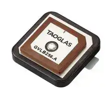
GVLB256.A
RF Antenna, 1.603GHz, Right Hand Circular, 2.61dBi, Pin Feed
⚠️ Reference pricing provided. In case of supply shortages, we will connect you with our trusted procurement partners to ensure your project's continuity.
- Manufacturer: TAOGLAS
- Product type:
- Gain: 2.61dBi
- SVHC: No SVHC (21-Jan-2025)
- VSWR: 3
- Input Power: -
- Antenna Type: GPS L1 / L5 / GNSS / Glonass G1 / Galileo E1 / E5a / BeiDou B1 / B2a / IRNSS / L-Band / Patch
- Frequency Max: 1.603GHz
- Frequency Min: -
- Product Range: -
- Input Impedance: 50ohm
- Antenna Mounting: Pin Feed
- Antenna Polarisation: Right Hand Circular
| Delivery and price | |
|---|---|
| Units per pack | 500 |
| Price | 2.54 € |
| Current stock | 50+ |
| Lead time | 30 days |
Datasheet

## Le A TAOGLAS. 49 Do QD ig7 Y) a0) 45 av) C) **Part No: GVLB256.A** **Description** GPS/GLONASS/BeiDou Single Feed Stacked Patch L1:1575MHz L5:1176.45MHz B1:1561MHz 25 x 25 x 6mm **Features:** Single Feed Stacked Patch Assembly Covering the following Bands & Constellations: – GPS L1 & L5 – BeiDou B1/B2a – Galileo E1 & E5a – GLONASS G1 Pin Mount Dims: 25mm x 25mm x 6mm RoHS & Reach Compliant SPE-25-8-086-A www.taoglas.com **==> picture [358 x 218] intentionally omitted <==** **----- Start of picture text -----**<br> 1. Introduction 3<br>2. Specification 4<br>3. Mechanical Drawing 6<br>4. Antenna Integration Guide 7<br>5. Packaging 13<br>6. Antenna Characteristics 14<br>7. Radiation Patterns 18<br>Changelog 23<br>**----- End of picture text -----**<br> Taoglas makes no warranties based on the accuracy or completeness of the contents of this document and reserves the right to make changes to specifications and product descriptions at any time without notice. Taoglas reserves all rights to this document and the information contained herein. Reproduction, use or disclosure to third parties without express permission is strictly prohibited. 2 www.taoglas.com SPE-25-8-086-A The Taoglas GVLB256.A, is a dual-band GNSS L1/L5, high-performance antenna for high precision GNSS accuracy and fast positioning. It utilizes a 25 x 25 x 6mm advanced wide-band dual-stacked ceramic patch antenna with optimized gain for GPS L1/L5, Galileo, GLONASS and BeiDou. At 6mm in height, the GVLB256.A has a smaller form factor allowing for installation where height is at a premium. Typical Applications Include: - Automotive Navigation Systems - Transportation - Drones & UAVs - Agriculture - Industrial IoT Devices - Timing & Synchronization The GVLB256.A has been tuned and tested on a 70 x 70 mm ground plane and exhibits excellent radiation patterns, it has been optimized to cover the bands required for the next generation of L1/L5 GNSS receivers that are currently on the market. Patch antennas can be specifically tuned to customer-specific device environments, subject to NRE and MOQ. Contact your regional Taoglas customer support team to request these services or additional support to integrate and test this antenna’s performance in your device. 3 www.taoglas.com SPE-25-8-086-A |**GNSS Frequency Bands**|**GNSS Frequency Bands**|**GNSS Frequency Bands**|**GNSS Frequency Bands**|**GNSS Frequency Bands**|**GNSS Frequency Bands**| |---|---|---|---|---|---| |**GPS**|**L1**<br>**1575.42 MHz**|**L2**<br>**1227.6 MHz**|**L5**<br>**1176.45 MHz**||| ||◼||◼||| |**GLONASS**|**G1**<br>**1602 MHz**|**G2**<br>**1248 MHz**|**G3**<br>**1207 MHz**||| ||◼||||| |**Galileo**|**E1**<br>**1575.24 MHz**|**E5a**<br>**1176.45 MHz**|**E5b**<br>**1201.5 MHz**|**E6**<br>**1278.75 MHz**|| ||◼|◼|||| |**BeiDou**|**B1C**<br>**1575.42 MHz**|**B1I**<br>**1561 MHz**|**B2a**<br>**1176.45 MHz**|**B2b**<br>**1207.14 MHz**|**B3**<br>**1268.52 MHz**| ||◼|◼|◼||| |**L-Band**|**L-Band**<br>**1542 MHz**||||| ||||||| |**QZSS (Regional)**|**L1**<br>**1575.42 MHz**|**L2C**<br>**1227.6 MHz**|**L5**<br>**1176.45 MHz**|**L6**<br>**1278.75e6**|| ||◼||◼||| |**IRNSS (Regional)**|**L5**<br>**1176.45 MHz**||||| ||◼||||| |**SBAS**|**L1/E1/B1**<br>**1575.42 MHz**|**L5/B2a/E5a**<br>**1176.45 MHz**|**G1**<br>**1602 MHz**|**G2**<br>**1248 MHz**|**G3**<br>**1207 MHz**| ||◼|◼|◼||| GNSS Bands and Constellations 4 www.taoglas.com SPE-25-8-086-A |||||| |---|---|---|---|---| ||**GNSS Electrical**|||| |||||| |||||| |**Frequency (MHz)**|**1176.45**|**1561**|**1575.42**|**1603**| |||||| |||||| |**VSWR (max.)**|3:1|||| |||||| |||||| |**Efficiency (%)**|56.01|50.89|53.37|60.44| |||||| |||||| |**Gain (dBi)**|1.18|1.71|2.09|2.61| |||||| |||||| |**Polarization**|RHCP|||| |||||| |||||| |**Impedance**|50 Ω|||| |||||| ||**Mechanical**| |---|---| ||| |**Dimensions**|25 x 25 x 6mm| ||| ||| |**Ground Plane**|70 x 70mm| ||| ||| |**Weight**|21g| ||| ||| |**Material**|Ceramic| ||| ||| |**Antenna Type**|Patch & Pin| ||| ||**Environmental**| |---|---| ||| |**Operation Temperature**|-40°C to 105°C| ||| ||| |**Storage Temperature**|-40°C to 105°C| ||| ||| |**Relative Humidity**|Non-condensing 65°C 95% RH| ||| 5 www.taoglas.com SPE-25-8-086-A 6 www.taoglas.com SPE-25-8-086-A The following is an example on how to integrate the GVLB256.A into a design. The GVLB256.A has one pin which is used for the RF Feed. Taoglas recommends using a minimum of 70x70mm ground plane to ensure optimal performance. Top view of an example 70x70mm PCB Reference Design. 7 www.taoglas.com SPE-25-8-086-A ## **4.1** Schematic Symbol and Pin Definitions a Top view of an example 70x70mm PCB Reference Design. The circuit symbol for a GVLB256.A is shown below. The antenna has 1 pin as indicated below. |Pin<br>~~a~~|Description| |---|---| |1<br>~~a~~|RF Feed| Above is a schematic symbol of the GVLB256.A and a table of the pin definitions. 8 www.taoglas.com SPE-25-8-086-A ## **4.2** Antenna Footprint 2 **==> picture [411 x 217] intentionally omitted <==** **----- Start of picture text -----**<br> BOTTOM<br>TOP<br>Pin Description<br>ee<br>1 RF Feed<br>**----- End of picture text -----**<br> 9 www.taoglas.com SPE-25-8-086-A ## **4.3** Copper Clearance = The footprint and clearance on the PCB must comply with the antenna’s specification. The PCB layout shown in the diagrams below demonstrates the GVLB256.A clearance area for Pin 1 (RF Feed Pad). The bottom copper keep out area only applies to the bottom layer and the top copper keep out area applies to all other layers. There should be a Ø3mm copper clearance around the antenna pins on the top side of the PCB with a Ø3.5mm copper clearance around the antenna pins on the bottom side. TOP SIDE BOTTOM SIDE 2D Images of Copper Clearances for the GVLB256.A 10 www.taoglas.com SPE-25-8-086-A ## Antenna Integration The GVLB256.A should be placed in the centre of the PCB to take advantage of the ground plane. The RF traces must maintain a 50 Ohm transmission line. Ground vias should be placed around the copper clearance area and the transmission line. Note that depending on the design application, tuning may be required for optimal performance. This may be achieved using a ‘pi’ matching network or custom tuning of the patch antenna. Bottom view of the PCB Reference Design, showing transmission lines and integration notes. 11 www.taoglas.com SPE-25-8-086-A ## Final Integration The bottom side image shown below highlights the antenna transmission line. Taoglas recommends using a minimum of 70x70mm ground plane to ensure optimal performance. Top Side (70x70mm example PCB Reference Design) Bottom Side 12 www.taoglas.com SPE-25-8-086-A 13 www.taoglas.com SPE-25-8-086-A ## Test Setup VNA Test Set-up 14 www.taoglas.com SPE-25-8-086-A ## Return Loss ## VSWR 15 www.taoglas.com SPE-25-8-086-A **==> picture [58 x 13] intentionally omitted <==** **----- Start of picture text -----**<br> Efficiency<br>**----- End of picture text -----**<br> ## Average Gain 16 www.taoglas.com SPE-25-8-086-A ## Peak Gain ## Axial Ratio 17 www.taoglas.com SPE-25-8-086-A ## Test Setup Chamber Test Set-up 18 www.taoglas.com SPE-25-8-086-A ## Patterns at 1176 MHz ## XZ Plane ## YZ Plane ## XY Plane 19 www.taoglas.com SPE-25-8-086-A ## Patterns at 1561 MHz ## XZ Plane ## YZ Plane **==> picture [44 x 9] intentionally omitted <==** **----- Start of picture text -----**<br> XY Plane<br>**----- End of picture text -----**<br> 20 www.taoglas.com SPE-25-8-086-A ## Patterns at 1575 MHz ## XZ Plane ## YZ Plane ## XY Plane 21 www.taoglas.com SPE-25-8-086-A ## Patterns at 1603 MHz ## XZ Plane ## YZ Plane **==> picture [44 x 9] intentionally omitted <==** **----- Start of picture text -----**<br> XY Plane<br>**----- End of picture text -----**<br> 22 www.taoglas.com SPE-25-8-086-A Changelog for the datasheet **SPE-25-8-086 – GVLB256.A** ## **Revision: A (Original First Release)** Date: 2025-03-18 Notes: Initial Release Author: Gary West **Previous Revisions** **==> picture [501 x 480] intentionally omitted <==** 23 www.taoglas.com SPE-25-8-086-A 24 www.taoglas.com SPE-25-8-086-A
Updated at June 9, 2026
About Novapart
Novapart is a B2B electronic component broker specialising in stock shortages and cost reduction. We source hard-to-find parts and identify compliant alternatives across a catalogue of 410,000+ components from 500+ manufacturers.
Learn more →Stock Shortage Specialist
When a component is unavailable, discontinued or has an unacceptable lead time, we tap into our network of vetted European and Asian distributors to source what you need — without compromising on quality or traceability.
Request a quote →Compliant Alternatives
We identify pin-to-pin, electrically equivalent substitutes that meet the same certifications (RoHS, AEC-Q100, REACH) as your original specification — validated against datasheets, not just part numbers. Often at a lower cost.
BOM Analysis service →