
Image not available
Illustrative purposes only

G30.B.108111
829MHZ, 2.4GHZ CDMA, DCS, EDGE, GPR
⚠️ Reference pricing provided. In case of supply shortages, we will connect you with our trusted procurement partners to ensure your project's continuity.
- Manufacturer: TAOGLAS / PARTNER STOCK
- Product type:
- SVHC: No SVHC (07-Nov-2024)
| Delivery and price | |
|---|---|
| Units per pack | 9 |
| Price | 27.41 € |
| Current stock | 10+ |
| Lead time | 30 days |
Datasheet

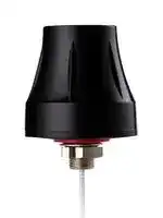
## **SPECIFICATION** Part No. : **G30.B.108111** - Product Name : Olympian Direct Mount Ultra Wide-Band 4G/3G/2G LTE / Cellular / CDMA / Wi-Fi Antenna For 2G/3G/4G Applications Feature - : LTE / GSM / CDMA / DCS / PCS / WCDMA / UMTS / HSDPA / GPRS / EDGE / IMT 698 to 960MHz, 2.4GHz and 1710 to 2700MHz Heavy duty screw mount UV and Features vandal resistant ABS housing and thread IP67 compliant Standard is 1M RG-316 SMA(M) Cables and Connectors Customizable RoHS Compliant SPE-12-8-149/N/AS Page 1 of 21 ## **1.Introduction** The G30 Olympian is a high performance screw mount wide-band cellular antenna for external use on vehicles and outdoor assets worldwide. Omni-directional high gain and high efficiency across all bands ensures constant reception and transmission. This is vital for today's high data bandwidth applications in video and mobile broadband. Durable UV resistant ABS housing is resistant to vandalism and direct attack. At only 48mm height it complies with the latest EU height restrictions directives for roof-mounted objects. This antenna is mounted on metal and plastic structures and is locked from the inside of the structure by a nut. Adhesive foam at the base provides a watertight seal to the mounting structure. High quality waterproof and corrosion resistant Teflon jacket RG316 is used for the cable. Two of these G30 separated at distance from each other are ideal for the latest LTE MIMO spatial diversity applications. Customized cable length and connectors are available. Taoglas recommend a minimum cable length of 70mm when used on a ground plane to achieve an efficiency of greater than 40% in the 900MHz band and greater than 60% in the 1800MHz band. For longer cable lengths and if 700MHz band is required, it is necessary to use the MA740 Pantheon for 4G/3G/2G or the MA741 4G/3G/2G MIMO Pantheon. SPE-12-8-149/N/AS Page 2 of 21 ## **2. Specification** |ELECTRICAL<br>~~es~~|ELECTRICAL<br>~~es~~|ELECTRICAL<br>~~es~~|ELECTRICAL<br>~~es~~|ELECTRICAL<br>~~es~~|ELECTRICAL<br>~~es~~|ELECTRICAL<br>~~es~~| |---|---|---|---|---|---|---| |Standard<br>~~es~~|4G/3G/2G<br>~~es~~|||||2.4GHz<br>~~es~~| |Operation<br>Frequency (MHz)|700~960|1710~2170|2305~2360|2500~2800|3400~3500|2400~2483| |Peak Gain|1.2 dBi|3.2dBi||2.5dBi||1.5dBi| |Average Gain|-4.5 dB|-2.5dB||-4.5dB||-4.5dB| |Efficiency|40%|55%||40%||38%| |VSWR|<3.0:1|||||| |Impedance|50Ω|||||| |Polarization|Linear|||||| |Radiation Properties|Omni-directional|||||| |Max Input Power|5 W|||||| * The G30 antenna performance was measured with 30X30 cm metal plate. |Dimensions(mm)<br>~~LT~~|Height=48mm and Diameter=50mm<br>~~LT~~| |---|---| |Cable|Length=1m RG316*| |Casing|UV Resistant ABS| |Base and Thread|Nickelplated steel| |Weatherproofgasket|CR4305 foam with 3M9448B double-side adhesive| |Connector|SMA(M)FullyCustomizable| |Nut|Nut M12 -| |Sealant|Rubber Stopper| |Weight|66g| |Recommended Torque|2.94N·m| |Max Torque|3.92N·m| *Minimum cable length 1M ## ~~LT~~ ENVIRONMENTAL |Protection<br>~~LT~~|IP67<br>~~LT~~| |---|---| |Corrosion|5% NACI for 96hrs- Nickelplated steel base and thread| |Temperature Range|-40ºC to +85ºC| |Thermal Shock|100 cycles -40ºC to +85ºC| |Humidity|Non-condensing 65 C 95% RH| |Shock (Drop Test)|1m drop on concrete 6 axes| |Cable Pull|8Kgf| SPE-12-8-149/N/AS Page 3 of 21 |LTE BANDS<br>~~CO~~|LTE BANDS<br>~~CO~~|LTE BANDS<br>~~CO~~|LTE BANDS<br>~~CO~~| |---|---|---|---| |Band Number<br>~~COa~~|LTE / LTE-Advanced / WCDMA / HSPA / HSPA+ / TD-SCDMA||| ||**Uplink**|**Downlink**|**Covered**| |**1**|UL: 1920 to 1980|DL: 2110 to 2170|✓| |**2**|UL: 1850 to 1910|DL: 1930 to 1990|✓| |**3**|UL: 1710 to 1785|DL: 1805 to 1880|✓| |**4**|UL: 1710 to 1755|DL: 2110 to 2155|✓| |**5**|UL: 824 to 849|DL: 869 to 894|✓| |**7**|UL: 2500 to 2570|DL:2620 to 2690|✓| |**8**|UL: 880 to 915|DL: 925 to 960|✓| |**9**|UL: 1749.9 to 1784.9|DL: 1844.9 to 1879.9|✓| |**11**|UL: 1427.9 to 1447.9|DL: 1475.9 to 1495.9|| |**12**|UL: 699 to 716|DL: 729 to 746|✓| |**13**|UL: 777 to 787|DL: 746 to 756|✓| |**14**|UL: 788 to 798|DL: 758 to 768|✓| |**17**|UL: 704 to 716|DL: 734 to 746 (LTE only)|✓| |**18**|UL: 815 to 830|DL: 860 to 875 (LET only)|✓| |**19**|UL: 830 to 845|DL: 875 to 890|✓| |**20**|UL: 832 to 862|DL: 791 to 821|✓| |**21**|UL: 1447.9 to 1462.9|DL: 1495.9 to 1510.9|| |**22**|UL: 3410 to 3490|DL: 3510 to 3590|| |**23**|UL:2000 to 2020|DL: 2180 to 2200 (LTE only)|✓| |**24**|UL:1625.5 to 1660.5|DL: 1525 to 1559 (LTE only)|| |**25**|UL: 1850 to 1915|DL: 1930 to 1995|✓| |**26**|UL: 814 to 849|DL: 859 to 894|✓| |**27**|UL: 807 to 824|DL: 852 to 869 (LTE only)|✓| |**28**|UL: 703 to 748|DL: 758 to 803 (LTE only)|✓| |**29**|UL: -|DL: 717 to 728 (LTE only)|✓| |**30**|UL: 2305 to 2315|DL: 2350 to 2360 (LTE only)|✓| |**31**|UL: 452.5 to 457.5|DL: 462.5 to 467.5 (LTE only)|| |**32**|UL: -|DL: 1452 - 1496|| |**35**|1850 to 1910||✓| |**38**|2570 to 2620||✓| |**39**|1880 to 1920||✓| |**40**|2300 to 2400||✓| |**41**|2496 to 2690||✓| |**42**|3400 to 3600||| |**43**|3600 to 3800||| *Covered bands represent an efficiency greater than 20% SPE-12-8-149/N/AS Page 4 of 21 ## **1. Test Setup** **==> picture [107 x 274] intentionally omitted <==** **----- Start of picture text -----**<br> Z<br>Y X<br>Z<br>Y X<br>**----- End of picture text -----**<br> **Figure 1.** Impedance Test Setup of G30 Antenna in Free Space, 30cmx30cm metal plate (left hand) and peak gain, average gain, efficiency and radiation pattern measurements (right hand) SPE-12-8-149/N/AS Page 5 of 21 ## **3.Antenna Parameters** ## **1.1. Return Loss** **Figure 2.** Return loss of G30 Antenna in Free Space **Figure 3.** Return Loss of G30 Antenna on 30x30cm metal SPE-12-8-149/N/AS Page 6 of 21 ## **1.2. VSWR** **Figure 4.** VSWR of G30 Antenna in Free Space **Figure 5.** VSWR of G30 Antenna on 30x30cm metal . SPE-12-8-149/N/AS Page 7 of 21 ## **1.3. Efficiency** **Figure 6.** Efficiency of G30 Antenna in Free Space **Figure 7.** Efficiency of G30 Antenna on 30x30cm metal SPE-12-8-149/N/AS Page 8 of 21 **Figure 8.** Efficiency of G30 Antenna at 2.4 GHz in Free Space. **Figure 9.** Efficiency of G30 Antenna at 2.4 GHz on metal plate 30x30 cm. SPE-12-8-149/N/AS Page 9 of 21 ## **1.4. 4.4. Peak Gain** **Figure 10.** Peak Gain of G30 Antenna in Free Space **Figure 11.** Peak Gain of G30 Antenna on 30x30cm metal SPE-12-8-149/N/AS Page 10 of 21 **Figure 12.** Peak Gain of G30 Antenna at 2.4 GHz in Free Space. **Figure 13.** Peak Gain of G30 Antenna at 2.4 GHz on metal plate. SPE-12-8-149/N/AS Page 11 of 21 ## **1.5. Average Gain** **Figure 14.** Average Gain of G30 Antenna in Free Space **Figure 15.** Average Gain of G30 Antenna on 30*30cm metal. SPE-12-8-149/N/AS Page 12 of 21 **Figure 16.** Average Gain of G30 Antenna at 2.4 GHz in free space. **Figure 17.** Average Gain of G30 Antenna at 2.4GHz on 30*30cm metal plate. SPE-12-8-149/N/AS Page 13 of 21 ## **1.6. Radiation Pattern** **Figure 18.** Radiation Pattern at 751MHz of G30 Antenna in Free Space **Figure 20.** Radiation Pattern at 915MHz of G30 Antenna in Free Space **Figure 22.** Radiation Pattern at 1805MHz of G30 Antenna in Free Space **Figure 19.** Radiation Pattern at 849MHz of G30 Antenna in Free Space **Figure21.** Radiation Pattern at 1710MHz of G30 Antenna in Free Space **Figure 23.** Radiation Pattern at 1910MHz of G30 Antenna in Free Space SPE-12-8-149/N/AS Page 14 of 21 **Figure 24.** Radiation Pattern at 1990MHz of G30 Antenna in Free Space **Figure 26.** Radiation Pattern at 2600MHz of G30 Antenna in Free Space **Figure 28.** Radiation Pattern at 849MHz of G30 Antenna on 30*30cm metal **Figure 25.** Radiation Pattern at 2100MHz of G30 Antenna in Free Space **Figure 27.** Radiation Pattern at 751MHz of G30 Antenna on 30*30cm metal **Figure 29.** Radiation Pattern at 915MHz of G30 Antenna on 30*30cm metal. SPE-12-8-149/N/AS Page 15 of 21 **Figure 30.** Radiation Pattern at 1710MHz of G30 Antenna on 30*30cm metal. **Figure 32.** Radiation Pattern at 1910MHz of G30 Antenna on 30*30cm metal **Figure 34.** Radiation Pattern at 2110MHz of G30 Antenna on 30*30cm metal. **Figure 31.** Radiation Pattern at 1805MHz of G30 Antenna on 30*30cm metal. **Figure 33.** Radiation Pattern at 1990MHz of G30 Antenna on 30*30cm metal. **Figure 35.** Radiation Pattern at 2595MHz of G30 Antenna on 30*30cm metal. SPE-12-8-149/N/AS Page 16 of 21 **Figure 36.** Radiation Pattern at 2400MHz of G30 Antenna on 30*30cm metal plate. SPE-12-8-149/N/AS Page 17 of 21 ## **2. Mechanical Drawing (Unit: mm)** **Figure 37.** Mechanical Drawing of the G30 Antenna SPE-12-8-149/N/AS Page 18 of 21 ## **3. Installation** SPE-12-8-149/N/AS Page 19 of 21 ## **4. Packaging** SPE-12-8-149/N/AS Page 20 of 21 Taoglas makes no warranties based on the accuracy or completeness of the contents of this document and reserves the right to make changes to specifications and product descriptions at any time without notice. Taoglas reserves all rights to this document and the information contained herein. Reproduction, use or disclosure to third parties without express permission is strictly prohibited. Copyright © Taoglas Ltd. SPE-12-8-149/N/AS Page 21 of 21
Updated at June 9, 2026
About Novapart
Novapart is a B2B electronic component broker specialising in stock shortages and cost reduction. We source hard-to-find parts and identify compliant alternatives across a catalogue of 410,000+ components from 500+ manufacturers.
Learn more →Stock Shortage Specialist
When a component is unavailable, discontinued or has an unacceptable lead time, we tap into our network of vetted European and Asian distributors to source what you need — without compromising on quality or traceability.
Request a quote →Compliant Alternatives
We identify pin-to-pin, electrically equivalent substitutes that meet the same certifications (RoHS, AEC-Q100, REACH) as your original specification — validated against datasheets, not just part numbers. Often at a lower cost.
BOM Analysis service →