
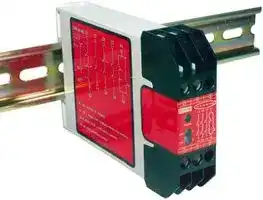


ES-FA-6G
RELAY, SAFETY, 3PST-NO, 250V, 6A
- Manufacturer: BANNER ENGINEERING
- Product type: Safety Relays
- IP Rating: IP20, IP40, IP54
- Coil Voltage: 24V
- Product Range: ES-FA Series
- Relay Mounting: DIN Rail
- Contact Current: 6A
- Relay Terminals: Screw
- Contact Configuration: 3PST-NO
- Contact Voltage AC Nom: 250V
- Contact Voltage DC Nom: 250V
| Delivery and price | |
|---|---|
| Units per pack | 5 |
| Price | 153.15 € |
| Current stock | 10+ |
| Lead time | 30 days |
**==> picture [7 x 7] intentionally omitted <==**

**----- Start of picture text -----**<br>
®<br>**----- End of picture text -----**<br>


## **ES-FA-6G 1-Channel Emergency Stop Safety Module**

24V ac/dc operation

## ~~**E-Stop Safety Module Features**~~

- Monitors one single-channel normally closed Emergency Stop switch circuit for a contact failure or wiring fault

- Three output switching channels for connection to control-reliable power interrupt circuits

- Auto reset or manual reset

- One auxiliary non-safety N/C output contact for status monitoring by process controller

- Design complies with standards UL991, EN418, and EN954-1 (Safety Category 2)

- For use in functional stop category 0 applications per NFPA 79 and EN418

- 6 amp safety output contacts

**==> picture [13 x 26] intentionally omitted <==**

**----- Start of picture text -----**<br>
!<br>**----- End of picture text -----**<br>


**WARNING . . . This Emergency Stop Safety Module is not a point-of-operation guarding device, as defined by OSHA regulations.** It is necessary to install point-of-operation guarding devices, such as safety light curtains and/or hard guards, to protect personnel from hazardous machinery. **Failure to install point-ofoperation guards on hazardous machinery can result in a dangerous condition which could lead to serious injury or death.**

Jan 2013

p/n 55581 Rev. BP/N 55581B9A

Printed in USA

**– Model ES-FA-6G E-Stop Safety Module**

## !

## **... Important read this page before proceeding!**

Banner Engineering Corp. has made every effort to provide complete application, installation, operation, and maintenance instructions. In addition, any questions regarding the use or installation of this Banner Emergency Stop Safety Module should be directed to the factory applications department at the telephone numbers or address shown on back cover.

The user shall ensure that all machine operators, maintenance personnel, electricians, and supervisors are thoroughly familiar with and understand all instructions regarding the installation, maintenance, and use of this Emergency Stop Safety Module, and with the machinery it controls.

The user and any personnel involved with the installation and use of this model Emergency Stop Safety Module must be thoroughly familiar with all applicable ANSI/NFPA standards. The standards, listed below, directly address the use of emergency stop systems. Banner Engineering Corp. makes no claim regarding a specific recommendation of any organization, the accuracy or effectiveness of any information provided, or the appropriateness of the provided information for a specific application.

The user has the responsibility to ensure that all local, state, and national laws, rules, codes, and regulations relating to the use of this Emergency Stop Safety Module in any particular application are satisfied. Extreme care is urged that all legal requirements have been met and that all installation and maintenance instructions contained in this manual are followed.

## **U. S. Standards Applicable to Use of Emergency Stop Safety Modules**

|ANSI B11|Standards for Machine Tools  “Safety Requirements for the Construction, Care and Use”|
|---|---|
||Available from:<br>Safety Director|
||AMT – The Association for Manufacturing Technology|
||7901 Westpark Drive|
||McLean, VA 22101-4269|
||Tel.: 703-827-5266|
|NFPA79|“Electrical Standard for Industrial Machinery (1997)”|
||Available from:<br>National Fire Protection Association|
||1 Batterymarch Park, P.O. Box 9101|
||Quincy, MA 02269-9101|
||Tel.: 800-344-3555|
|ANSI/RIA R15.06|“Safety Requirements for Industrial Robots and Robot Systems”|
||Available from:<br>Robotic Industries Association|
||900 Victors Way, P.O. Box 3724|
||Ann Arbor, MI 48106|
||Tel.: 734-994-6088|
|**European Standards Applicable to Use of Emergency Stop Safety Modules**||
|EN292-1|“Safety of Machinery – Basic Concepts, General Principals for Design|
||Part 1: Basic Terminology, Methodology”|
|EN292-2|“Safety of Machinery – Basic Concepts, General Principals for Design|
||Part 2: Technical Principals and Specifications”|
|EN60204-1|“Electrical Equipment of Machines: Part 1: General Requirements”|
||Also, request a type “C” standard for your specific machinery.|
|EN418|“Safety of Machinery – Emergency Stop Equipment Functional Aspects, Principles for Design”|
||Available from:<br>Global Engineering Documents|
||15 Inverness Way East|
||Englewood, CO 80112-5704|
||Tel.: 800-854-7179|


page 2

## **– Model ES-FA-6G E-Stop Safety Module**

## ~~**E-Stop Safety Module Description**~~

The purpose of an Emergency Stop Safety Module (E-Stop Safety Module) is to increase the control reliability of an emergency stop circuit. The ANSI B11.19 standard states:

“Control reliability of electrical, electronic, or pneumatic systems frequently consists of multiple, independent parallel or series circuitry or components so arranged that any single failure ... **either sends a stop command to the machine tool or prevents a successive cycle from being initiated.”**

In a functional Category 0 emergency stop circuit, opening of the E-stop switch contact(s) immediately removes power from the machine control elements, which react to arrest machine hazards. As indicated in Figures 3, 4, and 5, the model ES-FA-6G E-Stop Safety Module is designed for use with a 1-channel E-stop switch.  A 1-channel E-stop switch has one contact.

The customer-supplied E-stop switch must be a “positive-opening device.”  This means that its contact will open when the actuator is pushed with a certain minimum force, even if that contact was welded in the closed state.

As shown in Figure 2, the E-stop switch becomes an input to the E-Stop Safety Module. A short circuit between the two wires which connect the E-stop switch to the E-Stop Safety Module results in a unsafe condition. To reduce the possibility of a short circuit, the wires connecting the E-stop switch to the E-Stop Safety Module must be physically separated from each other and run in separate wireways or conduit.

The output of the E-Stop Safety Module consists of three redundant output switching channels, each of which is the series connection of two forced-guided relay contacts (K1 and K2 in Figure 2).

**==> picture [222 x 256] intentionally omitted <==**

**----- Start of picture text -----**<br>
13 23 33<br>A1 Y1 Y2<br>ES-FA-6G<br>13 23 33 41<br>Input Power<br>Power On<br>CH 1<br>CH 2<br>K1 Energized 14 24 34 42<br>41 42 A2<br>K2 Energized 14 24 34<br>**----- End of picture text -----**<br>


As recommended by the control reliability section of ANSI B11.19, relays K1 and K2 in the output circuit of the E-Stop Safety Module have mechanically linked contacts which allow the Safety Module circuitry to monitor the contacts of K1 and K2 for failure. If the Safety Module detects failure of any contact of the output relays, the Safety Module output is disabled and cannot be reset.

The E-Stop Safety Module also provides a necessary reset function. ANSI B11 and NFPA 79 standards require that a reset routine be performed after returning the E-stop switch to its closed-contact position. This prevents the controlled machinery from restarting by simply closing the E-stop switch. Model ES-FA-6G may be configured for automatic reset by connecting terminals Y1 and Y2 together (see Figure 2). **The automatic reset mode is useful for some automated processes.  However, when automatic reset is used, an alternate means must be established to require a reset routine after the E-stop switch is returned to its closed contact position (see WARNING on page 7).**

The three switching output circuits of the E-Stop Safety Module are rated for up to 250V ac at up to 6 amps. A normally closed non-safety auxiliary contact (between terminals #41 and 42) provides a monitoring signal for a process controller. This auxiliary contact is closed when the output circuits are open, and it is open when the output circuits are closed.

**Figure 1.  ES-FA-6G status indicators**

page 3

## **– Model ES-FA-6G E-Stop Safety Module**

This E-stop Safety Module complies with the following design standards:

- UL991 Tests for Safety Related Control Employing Solid-state Devices

EN418 Emergency Stop Equipment - Functional Aspects, Principals for Design

EN954-1 Safety of Machines: Safety-related Parts of Controllers Part 1: General Design Directives (Safety Category 2)

The Safety Module has indicators for input power and output relay contact status (K1 and K2); see Figure 1. There are no adjustments and no user-serviceable parts. See page 9 for information regarding repair service.

## ~~**E-Stop Switch Requirements**~~

As shown in Figure 3 or 4, the E-stop switch must provide one contact which is closed when the switch is in the “armed” position. Once activated, the E-stop switch must open this contact. The switch may be returned to the closed-contact position only by a deliberate action (such as twisting, pulling, or unlocking). Additionally, NFPA79 section 13.2, Emergency Stop Devices, specifies the following switch (“stop control”) requirements: • Emergency Stop push buttons shall be located at each operator control station and at other operating stations where emergency shutdown shall be required.

   - Stop and Emergency Stop push buttons shall be continuously operable from all control and operating stations where located.

   - Actuators of Emergency Stop devices shall be colored RED. The background immediately around the device actuator shall be colored YELLOW. The actuator of a push-button-operated device shall be of the palm or mushroomhead type.

   - The Emergency Stop actuator shall be a self-latching type.

- NOTE: Some applications may have additional requirements. The user must refer to all relevant regulations.

## ~~**Mechanical Installation**~~

The E-stop Safety Module must be installed inside an enclosure. It is not designed for exposed wiring. It is the user’s responsibility to house the Safety Module in an enclosure with NEMA 3 (IEC IP54) rating, or better.

Dimensions of the Safety Module are shown in the diagram on page 11. The Safety Module mounts directly to standard 35 mm DIN rail.

**CAUTION. . . Shock Hazard Always disconnect power from the E-stop Safety Module and all power from the machine being controlled before making any wire connections.**

Electrical installation and wiring must be made by qualified personnel and must comply with the NEC (National Electrical Code), EN602041 and -2, and all applicable local standards and codes.

page 4

## **– Model ES-FA-6G E-Stop Safety Module**

**==> picture [522 x 536] intentionally omitted <==**

**----- Start of picture text -----**<br>
+V dc common<br>24V ac/dc<br>Emergency<br>Stop Switch<br>WARNING . . .<br>If arc suppressors are<br>! used, they MUST be A1 A2<br>installed as shown<br>across the actuator coil of the<br>ES-FA-6G<br>Master Stop Control Elements<br>(MSC1 to MSC4).  NEVER install MSC1 MSC3<br>suppressors directly across the Y1<br>output contacts of the E-stop Safety MSC Monitor<br>Module . It is possible for Contacts<br>suppressors to fail as a short circuit. Y2<br>If installed directly across the output MSC2 Reset<br>contacts of the Safety Module,  a Switch<br>short-circuited suppressor will (jumper for auto reset -<br> see Warning on page 7)<br>create an unsafe condition which<br>could result in serious injury or Machine<br>death.<br>Master Stop<br>Control Elements<br>L1 6A max. L2<br>K1A K2A<br>WARNING . . . 13 14 MSC1<br>! NEVER wire anintermediate device (for<br>6A max.<br>logic controller), other than a Safetyexample, a programmable 23 K1B K2B 24 MSC2<br>Relay, between E-stop Safety Module<br>outputs and the Master Stop Control MachineControl<br>Element it switches.  sacrifices the control reliability of theTo do so Circuits K1C6A max.K2C<br>control-to-machine interface, and 33 34 MSC3<br>creates an unsafe condition which<br>could result in serious injury or death.<br>Whenever a Safety Relay is added as *Arc suppressors<br>an intermediate switching device, a K1D   (see WARNING)<br>normally closed forced-guided monitor<br>contact of that relay must be added to<br>K2D<br>the series feedback loop between 41 42<br>Safety Module terminals Y1 and Y2.<br>Non-safety<br>Auxiliary<br>(Reference ANSI B11.1 – 1988, Monitor Contact6A Max.<br>Appendix B4)<br>*<br>*<br>*<br>**----- End of picture text -----**<br>


**Figure 2.  Hookup of ES-FA-6G E-Stop Safety Module**

page 5

## **– Model ES-FA-6G E-Stop Safety Module**

## ~~**Electrical Installation**~~

It is not possible to give exact wiring instructions for a device such as an E-stop Safety Module which interfaces to a multitude of machine control configurations. The following guidelines are general in nature.

The ES-FA-6G has no delay function. Its output relay contacts open within 35 milliseconds after the E-stop switch contact opens. This classifies this E-stop Safety Module as a functional “Category 0” E-stop control as defined by NFPA 79 (National Fire Protection Association Standard for Industrial Machinery) and EN418 (European Standard: “Safety of Machinery, Emergency Stop Equipment, Functional Aspects – Principles of Design”).

## ~~**Connection of E-Stop Switch**~~

Connect the poles of the E-stop switches as shown in Figure 2. The switches in Figure 2 are shown in the “armed” position with both contacts closed. Multiple E-stop switches connected to one E-stop Safety Module must be series connected (see Figure 3 and the warning, on page 7).

## ~~**Connection to the Machine to be Controlled**~~

The hookup diagram (Figure 2) shows a generic connection of the E-stop Safety Module’s three redundant output circuits to Master Stop Control Elements MSC1 through MSC3. A Master Stop Control Element is defined as an electrically powered device, external to the E-stop Safety Module, which stops the machinery being controlled by immediately removing electrical power to the machine and (when necessary) by applying braking to dangerous motion (reference ANSI B11.19, section 5.2: “Stop Control”). This stopping action is accomplished by removing power to the actuator coil of either Master Stop Control Element.

**==> picture [166 x 122] intentionally omitted <==**

**----- Start of picture text -----**<br>
+24V ac/dc A1<br>**----- End of picture text -----**<br>


**Figure 3.  Series connection of multiple E-stop switches**

To satisfy the requirements of Safety Category 2 of prEN 954-1, the Master Stop Control Elements must offer a normally closed, forced-guided monitor contact. One normally closed monitor contact from each Master Stop Control Element is wired in series to the Y1-Y2 feedback/reset input (see Figure 2). In operation, if one of the switching contacts of either master stop control element fails in the shorted condition, the associated monitor contact will remain open. Therefore, it will not be possible to reset the E-stop Safety Module.

page 6

## **– Model ES-FA-6G E-Stop Safety Module**

## **WARNING . . .** ! **Multiple E-Stop Switches**

•  Whenever two or more E-stop switches are connected to the same E-stop Safety Module, the contacts of both switches must be connected together in series. This series combination is then wired to the respective Safety Module input. **Never connect the contacts of multiple E-stop switches in parallel to the E- stop Safety Module inputs; this defeats the switch contact monitoring ability of the Safety Module, and creates an unsafe condition which could result in serious injury or death.**

• **Also, when two or more E-stop switches are used, each switch must be individually actuated (engaged), then re-armed and the E-stop Safety Module reset** (if using manual reset mode).  This allows the monitoring circuits to check each switch and its wiring to detect faults. **Failure to test each switch individually in this manner could result in undetected faults and create an unsafe condition which could result in serious injury or death.**

## **WARNING . . . Reset Routine Required**

!

ANSI B11 and NFPA 79 standards require that a reset routine be performed after returning the E- stop switch to its closed-contact position (when arming the E-stop switch). When automatic reset is used, an alternate means must be established to require a reset routine, after the E-stop switch is armed. **Allowing the machine to restart as soon as the E-stop switch is armed creates an unsafe condition which could result in serious injury or death.**

## ~~**Connection of Reset Switch**~~

The Reset Circuit switch can be any mechanical switch such as a normally open momentary switch, or a two-position key switch. The Reset switch must be capable of reliably switching 12 to 18V dc at 40 to 100 milliamps. As shown in Figure 2, the Reset switch connects between terminals Y1 and Y2 of the Safety Module.

**The Reset switch must be located outside of – and not be accessible from – the area of dangerous motion, and must be positioned so that any area of dangerous motion may be observed by the switch operator during the Reset procedure.**

## ~~**Automatic Reset Mode**~~

Model ES-FA-6G may be configured for automatic reset by replacing the Reset switch with a jumper wire in the Y1-Y2 feedback/reset input circuit (see Figure 2). The E-stop Safety Module will reset (and the outputs energize) as soon as the E-stop switch returns to its closed-contact position.

The automatic reset mode is useful for some automated processes. **However, if automatic reset is used, it is necessary to provide an alternate means of preventing resumption of hazardous machine motion, until an alternate reset procedure is performed.** The alternate procedure must include a Reset switch, located outside the area of dangerous motion, which is positioned so that any area of dangerous motion may be observed by the switch operator during the reset procedure.

## ~~**Connection to Auxiliary Monitor Contact**~~

The action of the Auxiliary Monitor Contact, 41-42, inversely “follows” the action of output contacts 13-14, 23-24 and 33-34 when power is applied to the E-stop Safety Module. The contact 41-42 is open when the three normally open output contacts are closed, and vice versa. **The 41-42 Auxiliary Monitor Contact is to be used only for control functions that are NOT safety-related** . A typical use is to communicate the status of the Safety Module output to a programmable logic controller (PLC). The switching capacity of the 41-42 Auxiliary Monitor Contact is 250V ac/dc maximum at 6 A maximum (see product specifications on page 10).

NOTE: The MSC Monitor Contacts must remain in a series connection betweet Y1 and Y2. **DO NOT** install a jumper wire directly between Y1 and Y2.

page 7

## **– Model ES-FA-6G E-Stop Safety Module**

## ~~**Initial Checkout Procedure**~~

## Checkout procedure:

- 1) Remove power from the machine control elements.

- 2) Activate the E-stop switch (open its contact).

- 3) Apply power to one side of the E-stop switch. No indicator should be ON at this time. If any of the three indicators is ON, disconnect the power to the E-stop switch, then check all wiring and the E-stop switch. Return to step 2 after the cause of the problem has been corrected.

- 4) Arm the E-stop switch (close its contact). The Power LED must come ON.

- 5) NOTE: If configured for automatic reset, K1 and K2 indicators should come ON, and the safety output contacts should close.

If configured for manual reset, close the Reset switch. The K1 and K2 indicators should come ON. Open the Reset switch. The K1 and K2 indicators should both stay ON. If none or only one of the two K1 and K2 indicators comes ON, check the wiring. If the wiring is OK, the unit has an internal fault.

## **CAUTION . . . Disconnect Power Prior to Checkout**

**==> picture [41 x 41] intentionally omitted <==**

Before performing the initial checkout procedure, make certain all power is disconnected from the machine to be controlled. Dangerous voltages may be present along the E-stop Safety Module wiring barriers whenever power to the machine control elements is ON. **Exercise extreme caution whenever machine control power is or may be present. Always disconnect power to the machine control elements before opening the enclosure housing of the E-stop Safety Module.**

- 6) Activate the E-stop switch (open its contact). The K1 and K2 indicators should turn OFF simultaneously. If either indicator is not OFF, disconnect the input power and check all wiring. Return to step 2 after the cause of the problem has been corrected.

- 7) Close the enclosure. Apply power to the Machine Control Elements and perform the Periodic Checkout Procedure (see below).

   - **NOTE: If more than one E-stop switch is series-connected to one E-stop Safety Module, the above checkout procedure must be run individually for EACH switch.**

## ~~**Periodic Checkout Procedure**~~

The functioning of the E-stop system must be verified on a regular periodic basis to ensure proper operation (see also the machine manufacturer’s recommendations).

## Procedure:

- 1)  With the machine running, engage the E-stop switch (open its contact). Verify that the machine stops.

- 2)  Return the E-stop switch to its closed-contact position. Verify that the machine does not start.

- 3) Close and then open the Reset switch (if using manual reset mode). Verify that the machine restarts.

   - **NOTE: If two or more E-stop switches are series-connected to one E-stop Safety Module, this test must be individually run for EACH switch.**

page 8

## **– Model ES-FA-6G E-Stop Safety Module**

## ~~**Repairs**~~

**NOTE: Do not attempt any repairs to the ES-FA-6G Emergency Stop Safety Module. It contains no field-replaceable components. Return the Safety Module to the factory for warranty repair or replacement:**

If it ever becomes necessary to return an E-stop Safety Module to the factory, please do the following:

- 1) Contact the Banner Factory Application Engineering Group at the address or at the numbers listed at the bottom of the back page. They will attempt to troubleshoot the system from your description of the problem. If they conclude that a component is defective, they will issue an RMA (Return Merchandise Authorization) number for your paperwork, and give you the proper shipping address.

- 2) Pack the E-stop Safety Module carefully. Damage which occurs in return shipping is not covered by warranty.

page 9

## **– Model ES-FA-6G E-Stop Safety Module**

## ~~**E-Stop Safety Module Product Specifications**~~

**==> picture [522 x 418] intentionally omitted <==**

**----- Start of picture text -----**<br>
Supply Voltage and Current 24V ac/dc, +/- 10%; 50/60Hz<br>Power consumption: approx. 2W/0.75VA<br>Supply Protection Circuitry Protected against transient voltages and reverse polarity<br>Output Configuration Outputs (K1 & K2): three redundant (total of six) safety relay (forced-guided) contacts – AgSnO2<br>one auxiliary non-safety monitor output (open when both K1 and K2 are energized;<br>closed when either K1 or K2 are de-energized)<br>Contact ratings:<br>Maximum voltage: 250V ac or 250V dc<br>Maximum current: 6 A ac or dc<br>Minimum current: 30 mA @ 10V dc<br>Maximum power: 1500VA, 150W<br>Mechanical life: 10,000,000 operations<br>Electrical life: 100,000 at full resistive load<br>NOTE: Transient suppression is recommended when switching inductive loads.  Install suppressors<br>across load. Never install suppressors across output contacts (see Warning, page 5).<br>Output Response Time 35 milliseconds typical<br>Input Requirements E-stop switch must have a normally closed contact capable of switching 40 to 100mA @ 13 to 27V ac/dc.<br>Reset switch must have one normally open contact capable of switching 20 to 30mA @ 13 to 27V ac/dc.<br>Status Indicators 3 green LED indicators:<br>Power ON<br>K1 energized<br>K2 energized<br>Housing Polycarbonate. Rated NEMA 1; IEC IP40, Terminals IP20<br>Mounting Mounts to standard 35 mm DIN rail track. Safety Module must be installed inside an enclosure rated NEMA 3<br>(IEC IP54), or better.<br>Vibration Resistance 10 to 55Hz @ 0.35mm displacement per IEC 68-2-6<br>Operating Conditions Temperature:  0° to +50°C (+32° to 122°F)<br>Maximum Relative Humidity: 90% @ +50°C (non-condensing)<br>Dimensions See Figure 4.<br>**----- End of picture text -----**<br>


page 10

**– Model ES-FA-6G E-Stop Safety Module**

**==> picture [522 x 572] intentionally omitted <==**

**----- Start of picture text -----**<br>
13 23 33<br>A1 Y1 Y2<br>ES-FA-6G<br>13 23 33 41<br>Power<br>CH 1<br>CH 2<br>14 24 34 42<br>41 42 A2<br>14 24 34<br>WARRANTY VOID<br>IF OPENED<br>118.2 mm<br>(4.65")<br>22.5 mm<br>80 mm (.88")<br>(3.15")<br>82 mm<br>(3.23")<br>DIN Mounting 35.0 mm<br>Tab (Supplied) (1.38")<br>DIN Mounting Slot<br>**----- End of picture text -----**<br>


**Figure 4.  E-Stop Safety Module enclosure dimensions**

page 11

## **E-Sto Safet Module – Model ES-FA-6G p y**

Banner Engineering Corp Limited Warranty

Banner Engineering Corp. warrants its products to be free from defects in material and workmanship for one year following the date of shipment. Banner Engineering Corp. will repair or replace, free of charge, any product of its manufacture which, at the time it is returned to the factory, is found to have been defective during the warranty period. This warranty does not cover damage or liability for misuse, abuse, or the improper application or installation of the Banner product.

THIS LIMITED WARRANTY IS EXCLUSIVE AND IN LIEU OF ALL OTHER WARRANTIES WHETHER EXPRESS OR IMPLIED (INCLUDING, WITHOUT LIMITATION, ANY WARRANTY OF MERCHANTABILITY OR FITNESS FOR A PARTICULAR PURPOSE), AND WHETHER ARISING UNDER COURSE OF PERFORMANCE, COURSE OF DEALING OR TRADE USAGE.

This Warranty is exclusive and limited to repair or, at the discretion of Banner Engineering Corp., replacement. IN NO EVENT SHALL BANNER ENGINEERING CORP. BE LIABLE TO BUYER OR ANY OTHER PERSON OR ENTITY FOR ANY EXTRA COSTS, EXPENSES, LOSSES, LOSS OF PROFITS, OR ANY INCIDENTAL, CONSEQUENTIAL OR SPECIAL DAMAGES RESULTING FROM ANY PRODUCT DEFECT OR FROM THE USE OR INABILITY TO USE THE PRODUCT, WHETHER ARISING IN CONTRACT OR WARRANTY, STATUTE, TORT, STRICT LIABILITY, NEGLIGENCE, OR OTHERWISE.

Banner Engineering Corp. reserves the right to change, modify or improve the design of the product without assuming any obligations or liabilities relating to any product previously manufactured by Banner Engineering Corp.

**==> picture [166 x 79] intentionally omitted <==**

**----- Start of picture text -----**<br>
®<br>**----- End of picture text -----**<br>


**WARRANTY:** Banner Engineering Corporation warrants its products to be free from defects for one year. Banner Engineering Corporation will repair or replace, free of charge, any product of its manufacture found to be defective at the time it is returned to the factory during the warranty period.  This warranty does not cover damage or liability for the improper application of Banner products.  This warranty is in lieu of any other warranty either expressed or implied.

Banner Engineering Corp., 9714 Tenth Ave. No., Minneapolis, MN 55441 • Phone: 612.544.3164 • Fax: 612.544.3213 • Email: sensors@baneng.com
Updated at February 9, 2023
Founded in 1966, Banner Engineering is a globally recognized leader in the design and manufacture of industrial automation products. The company is renowned for developing innovative, high-quality solutions that improve operational efficiency, safeguard personnel, and optimize manufacturing processes across a diverse range of industries. Our extensive selection of Banner Engineering components prominently features their industry-leading sensing technologies. We offer a comprehensive array of precision light sensors engineered for accurate detection and measurement in demanding environments. Complementing this core sensing portfolio is a robust offering of automation signaling devices, including visual signal indicator units and essential accessories, which provide clear and immediate communication of machine status. Beyond primary sensing and indication solutions, our range encompasses critical components for broader process control and machine safety. This includes advanced process controllers, reliable pressure sensors and transducers, and dependable safety relays. Supported by a variety of purpose-built sensor accessories and fiber optic lead assemblies, Banner Engineering delivers the durable, high-performance technologies required to build and maintain sophisticated automated systems.
About Novapart
Novapart is a B2B electronic component broker specialising in stock shortages and cost reduction. We source hard-to-find parts and identify compliant alternatives across a catalogue of 410,000+ components from 500+ manufacturers.
Learn more →Stock Shortage Specialist
When a component is unavailable, discontinued or has an unacceptable lead time, we tap into our network of vetted European and Asian distributors to source what you need — without compromising on quality or traceability.
Request a quote →Compliant Alternatives
We identify pin-to-pin, electrically equivalent substitutes that meet the same certifications (RoHS, AEC-Q100, REACH) as your original specification — validated against datasheets, not just part numbers. Often at a lower cost.
BOM Analysis service →