
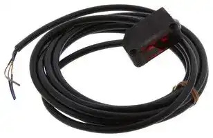


E3Z-R81
PHOTOELECTRIC SENSOR, 660NM RED LED
- Manufacturer: OMRON INDUSTRIAL AUTOMATION
- Product type:
- Sensor Type:Photoelectric Sensors; Sensing Method:Retroreflective; Output Type:PNP Open Collector; Product Range:E3Z Series; Connection Method:Cable; Supply Voltag 08C3812
- SVHC: To Be Advised
- IP Rating: IP67
- Output Type: PNP Open Collector
- Sensor Type: Photoelectric Sensors
- Light Source: 660nm Red LED
- Product Range: -
- Qualification: -
- Sensing Method: Retroreflective
- Connection Method: Cable
- Sensing Range Max: 4m
- Sensor Output Type: PNP
- Supply Voltage Max: 24VDC
- Supply Voltage Min: 12VDC
- Sensing Distance Max: 4m
- Supply Voltage DC Max: 24V
- Supply Voltage DC Min: 12V
- Operating Temperature Max: 55°C
- Operating Temperature Min: -25°C
| Delivery and price | |
|---|---|
| Units per pack | 25 |
| Price | 111.27 € |
| Current stock | 10+ |
| Lead time | 30 days |
**Compact Photoelectric Sensor with Built-in Amplifier E3Z** CSM_E3Z_DS_E_16_1 ## **The Standard for Photoelectric Sensors with a Secure Track Record of One Million Sold Yearly.** - Long sensing distance of 30 m for Through-beam Models, 4 m for Retro-reflective Models, and 1 m for Diffuse-reflective Models. - Mechanical axis and optical axis offset of less than ± 2.5 ° simplifies optical axis adjustment. - High stability with unique algorithm that prevents interference of external light. For the most recent information on models that have been certified for safety standards, refer to your OMRON website. Be sure to read _Safety Precautions_ on page 13. ~~a~~ ## **Features** **Industry's Top-level Sensing Distance with** Through-beam **Built-in Amplifier** A separately sold filter is available to prevent mutual interference for 30 m Through-beam Models with red lights sources and a sensing | ~~ae~~ distance of 10 m. Reflective Models include functionality to prevent Retro-reflective with MSR function Distance-settable mutual interference (up to 2 sensors). 4 m 20 cm Long-distance, Through-beam Sensors with a detection distance of ~~sf~~ | 30 m (response time: 2 ms) are also available. Diffuse-reflective 1 m | ~~[co]~~ ## **Low-temperature Operation for Applications in Cold-storage Warehouses** A wider ambient operating range from − 40 to 55 ° C (main models with connectors). We also provide Sensor I/O Connectors with PUR Cables for high resistance to cold environments. ## **Improved Matching of Optical Axis and Mechanical Axis for Through-beam Models and Retro-reflective Models** 30 m mechanical 2.5 ° max. axis om: Optical axis om The receiver will always be in the range of light diffusion. The offset between the optical axis and the mechanical axis is kept within ± 2.5 ° , so the optical axis can be accurately set simply by mounting the Sensor according to the mechanical axis. ## **Sensor Protection against Incorrect Wiring** Through-beam Model receivers and Reflective Models (except the E3Z-LS) **==> picture [200 x 63] intentionally omitted <==** **----- Start of picture text -----**<br> Brown 12 to 24 VDC<br>Operation Stability 1<br>indicator (orange) indicator(green) 100 mAmax. (relay)Load<br>Photo-electric 4 Black<br>Sensor ZD<br>main Blue<br>circuit 3<br>0 V<br>**----- End of picture text -----**<br> The Sensor includes output reverse polarity protection. (A diode to protect against reverse polarity is added to the output line.) Protection for NPN output models ## **Complete Compliance with the EU's RoHS Directive** Lead, mercury, cadmium hexachrome, polybrominated biphenyl (PBB), and polybrominated diphenyl ether (PBDE) have all been eliminated. Also, burnable polyethylene packaging has been used. **==> picture [13 x 8] intentionally omitted <==** **----- Start of picture text -----**<br> Pb<br>**----- End of picture text -----**<br> **1** **E3Z** ## **Ordering Information** **Sensors [Refer to** _**Dimensions on page**_ **14.]** ||||||||||||||| |---|---|---|---|---|---|---|---|---|---|---|---|---|---| |**Sensors[Refer to****_Dimensions on page_ 14.]**||||||||||||Red light<br>Infrared light|| |**Sensing method**||**Appearance**|||**Connection method**|**Sensing distance**||||||**Model**|| |||||||||||||**NPN output**|**PNP output**| |Through-beam<br>(Emitter + Receiver)<br>*3|||||Pre-wired (2 m)|||||15<br>10 m|m|**E3Z-T61 2M*4 *5**<br>Emitter<br>E3Z-T61-L 2M<br>Receiver E3Z-T61-D 2M|**E3Z-T81 2M*4 *5**<br>Emitter<br>E3Z-T81-L 2M<br>Receiver E3Z-T81-D 2M| ||||||||||||||| ||||||Standard M8 connector|||||||**E3Z-T66**<br>Emitter<br>E3Z-T66-L<br>Receiver E3Z-T66-D|**E3Z-T86**<br>Emitter<br>E3Z-T86-L<br>Receiver E3Z-T86-D| ||||||||||||||| ||||||Pre-wired (2 m)|||||||**E3Z-T61A 2M*4**<br>Emitter<br>E3Z-T61-A-L 2M<br>Receiver E3Z-T61-A-D 2M|**E3Z-T81A 2M*4**<br>Emitter<br>E3Z-T81-A-L 2M<br>Receiver E3Z-T81-A-D 2M| ||||||||||||||| ||||||Standard M8 connector|||||||**E3Z-T66A**<br>Emitter<br>E3Z-T66-A-L<br>Receiver E3Z-T66-A-D|**E3Z-T86A**<br>Emitter<br>E3Z-T86-A-L<br>Receiver E3Z-T86-A-D| ||||||||||||||| ||||||Pre-wired (2 m)|||||30m||**E3Z-T62 2M*4**<br>Emitter<br>E3Z-T62-L 2M<br>Receiver E3Z-T62-D 2M|**E3Z-T82 2M**<br>Emitter<br>E3Z-T82-L 2M<br>Receiver E3Z-T82-D 2M| ||||||||||||||| ||||||Standard M8 connector|||||||**E3Z-T67**<br>Emitter<br>E3Z-T67-L<br>Receiver E3Z-T67-D|**E3Z-T87**<br>Emitter<br>E3Z-T87-L<br>Receiver E3Z-T87-D| ||||||||||||||| |Retro-reflective with<br>MSR function||||*1|Pre-wired (2 m)|||||<br>mm)<br>*2||**E3Z-R61 2M*4 *5**|**E3Z-R81 2M*4 *5**| ||||||<br>Standard M8 connector|||4 m<br>(100||||<br>**E3Z-R66**|<br>**E3Z-R86**| |Diffuse-reflective|||||Pre-wired (2 m)|||<br>0 mm<br>iew)||||**E3Z-D61 2M*4**|**E3Z-D81 2M*4 *5**| |||||||5 to 10<br>(wide v|||||||| ||||||Standard M8 connector|||||||**E3Z-D66**|**E3Z-D86**| ||||||||||||||| ||||||Pre-wired (2 m)|||1 m||||**E3Z-D62 2M*4 *5**|**E3Z-D82 2M*4 *5**| ||||||||||||||| ||||||Standard M8 connector|||||||**E3Z-D67**|**E3Z-D87**| ||||||||||||||| ||||||Pre-wired (2 m)|90± <br>(nar||30 mm||||**E3Z-L61 2M*4 *5**|**E3Z-L81 2M*4 *5**| ||||||||||||||| ||||||Standard M8 connector|||row beam||)||**E3Z-L66**|**E3Z-L86**| |Distance-settable<br>Refer to**E3Z-LS**.|||||Pre-wired (2 m)|||||||**E3Z-LS61 2M*4**|**E3Z-LS81 2M*4**| |||||||20 to 40 m<br>20 to 200 m<br>40 min. Inci<br>200 min. In||m (BGS min se<br>m (BGS max||tting)<br>setting)|||| ||||||Standard M8 Connector|||dent threshold (F<br>cident threshold (F||GS min setting)<br>GS max settin|<br>g)|**E3Z-LS66**|**E3Z-LS86**| ||||||Pre-wired (2 m)|2 to 20<br>2 to 80||mm (BGS<br>mm (BGS||min settin<br>max setti|g)<br>ng)|**E3Z-LS63 2M**|**E3Z-LS83 2M*5**| ||||||Standard M8 connector|||||||**E3Z-LS68**<br>|**E3Z-LS88**| |Slit-type Through-<br>beam<br>Refer to**E3Z-G**.||||1 axis|Pre-wired (2 m)|||||||**E3Z-G61 2M*4 *5**|**E3Z-G81 2M*4 *5**| |||||2 axes||||||||**E3Z-G62 2M*4**|**E3Z-G82 2M*4**| |||||||25 mm|||||||| |||||1 axis|Pre-wired M8 connector|||||||**E3Z-G61-M3J**|**E3Z-G81-M3J**| ||||||||||||||| |||||2 axes||||||||**E3Z-G62-M3J**|**E3Z-G82-M3J**| |Limited-reflective for<br>transparent glasses|||||Pre-wired (2 m)|||mm||||**E3Z-L63 2M**|**E3Z-L83 2M**| |||||||30±20|||||||| ||||||Standard M8 connector|||||||**E3Z-L68**|**E3Z-J88**| ||||||||||||||| |Retro-reflective with-<br>out MSR function for<br>clear, plastic bottles||||*1|Pre-wired (2 m)|||||*2<br>||**E3Z-B61 2M**|**E3Z-B81 2M*4**| ||||||Standard M8 connector||500|mm (80||mm)||**E3Z-B66**|**E3Z-B86**| ||||||||||||||| ||||||Pre-wired (2 m)|||||*2||**E3Z-B62 2M*4**|**E3Z-B82 2M*4**| ||||||||||||||| ||||||Standard M8 connector||||2 m|(500 m|)|**E3Z-B67**|**E3Z-B87**| ||||||||||||||| - *1. The Reflector is sold separately. Select the Reflector model most suited to the application. - *2. The sensing distance specified is possible when the E39-R1S is used. Values in parentheses indicate the minimum required distance between the Sensor and Reflector. - *3. Through-beam Sensors are normally sold in sets that include both the Emitter and Receiver. - *4. M12 Standard Pre-wired Connector Models are also availavble. - When ordering, add "-M1J 0.3M" to the end of the model number (e.g., E3Z-T61-M1J 0.3M). The cable is 0.3 m long. *5. M12 Pre-wired Smartclick Connector Models are also availavble. When ordering, add "-M1TJ 0.3M" to the end of the model number (e.g., E3Z-T61-M1TJ 0.3M). The cable is 0.3 m long. **2** **E3Z** ## **Oil-resistive Sensors [Refer to** _**Dimensions on page**_ **14.]** |||||||||||| |---|---|---|---|---|---|---|---|---|---|---| |**Oil-resistive Sensors[Refer to****_Dimensions on page_ 14.]**|||||||||Red light<br>Infrared light|| |**Sensing method**|**Appearance**||**Connection method**|**Sensing distance**|||||**Model**|| ||||||||||**NPN output**|**PNP output**| |Through-beam<br>(Emitter + Receiver)*3|||Pre-wired (2 m)<br>Pre-wired M8 connector||||15|m|**E3Z-T61K 2M*4**<br>Emitter<br>E3Z-T61K-L 2M<br>Receiver E3Z-T61K-D 2M|**E3Z-T81K 2M*4**<br>Emitter<br>E3Z-T81K-L 2M<br>Receiver E3Z-T81K-D 2M| ||||||||||**E3Z-T61K-M3J 0.3M**<br>Emitter<br>E3Z-T61K-L-M3J 2M<br>Receiver E3Z-T61K-D-M3J 2M|**E3Z-T81K-M3J 0.3M**<br>Emitter<br>E3Z-T81K-L-M3J 2M<br>Receiver E3Z-T81K-D-M3J 2M| |||||||||||| |Retro-reflective with<br>MSR function||*|1<br>Pre-wired (2 m)<br>Pre-wired M8 connector||||*2|)|**E3Z-R61K 2M*4**|**E3Z-R81K 2M**| |||||||3 m|(150 mm||**E3Z-R61K-M3J 0.3M**|**E3Z-R81K-M3J 0.3M**| |Diffuse-reflective|||Pre-wired (2 m)<br>Pre-wired M8 connector<br>Pre-wired (2 m)<br>Pre-wired M8 connector|||||)|**E3Z-D61K 2M*4**|**E3Z-D81K 2M**| |||||5 to 10||0 mm (wi|de view|||| ||||||||||**E3Z-D61K-M3J 0.3M**|**E3Z-D81K-M3J 0.3M**| |||||||||||| ||||||||||**E3Z-D62K 2M*4**|**E3Z-D82K 2M**| ||||||1 m|||||| ||||||||||**E3Z-D62K-M3J 0.3M**|**E3Z-D82K-M3J 0.3M**| |||||||||||| *1. The Reflector is sold separately. Select the Reflector model most suited to the application. *2. The sensing distance specified is possible when the E39-R1S is used. Values in parentheses indicate the minimum required distance between the Sensor and Reflector. - *3. Through-beam Sensors are normally sold in sets that include both the Emitter and Receiver. - *4. M12 Standard Pre-wired Connector Models are also availavble. When ordering, add "-M1J 0.3M" to the end of the model number (e.g., E3Z-T61-M1J 0.3M). The cable is 0.3 m long. ## **Accessories (Order Separately)** **Slit (A Slit is not provided with Through-beam Sensors) Order a Slit separately if required. [Refer to** _**Dimensions**_ **on page 16.]** |**Slit width**|**Sensing distance**|**Sensing distance**|**Minimum detectable object**<br>**(Reference value)**|**Model**|**Contents**| |---|---|---|---|---|---| ||**E3Z-T**@@|**E3Z-T**@@**A**|||| |0.5-mm dia.|50 mm|35 mm|0.2-mm dia.|**E39-S65A**|One set<br>(contains Slits for<br>both the Emitter and<br>Receiver)| |1-mm dia.|200 mm|150 mm|0.4-mm dia.|**E39-S65B**|| |2-mm dia.|800 mm|550 mm|0.7-mm dia.|**E39-S65C**|| |0.5×10 mm|1 m|700 mm|0.2-mm dia.|**E39-S65D**|| |1×10 mm|2.2 m|1.5 m|0.5-mm dia.|**E39-S65E**|| |2×10 mm|5 m|3.5 m|0.8-mm dia.|**E39-S65F**|| **Reflectors (Reflector required for Retroreflective Sensors) A Reflector is not provided with the Sensor. Be sure to order a Reflector separately. [Refer to** _**Dimensions**_ **on** _**E39-L**_ **/** _**E39-S**_ **/** _**E39-R**_ **]** |**Name**|**Sensing distance***|**Sensing distance***|**Sensing distance***|**Sensing distance***|**Sensing distance***|**Model**|**Quantity**|**Remarks**| |---|---|---|---|---|---|---|---|---| ||**E3Z-R**||**E3Z-R**@**K**|**E3Z-B**@**1/-B**@**6**|**E3Z-B**@**2/-B**@**7**|||| ||**Rated value**<br>**(sensing**<br>**distance of 15 m)**<br>**R**<br>**d**|**eference value**<br>**(sensing**<br>**istance of 10 m)**|**Rated value**|**Rated value**|**Rated value**|||| |Reflector|3 m (100 mm)|---|2 m (100 mm)|---|---|**E39-R1**|1|•Retro-reflective<br>models are not<br>provided with<br>Reflectors.<br>•The MSR function<br>is enabled.| ||4 m (100 mm)|---|3 m (150 mm)|500 mm (80 mm)|2 m (500 mm)|**E39-R1S**|1|| ||---|5 m (100 mm)|---|---|---|**E39-R2**|1|| ||---|2.5 m (100 mm)|---|---|---|**E39-R9**|1|| ||---|3.5 m(100 mm)|---|---|---|**E39-R10**|1|| |Fog Preventive<br>Coating|---|3 m (100 mm)|---|500 mm (80 mm)|2 m (500 mm)|**E39-R1K**|1|| |Small Reflector|---|1.5 m(50 mm)|---|---|---|**E39-R3**|1|| |Tape Reflector|---|700 mm(150 mm)|---|---|---|**E39-RS1**|1|| ||---|1.1 m(150 mm)|---|---|---|**E39-RS2**|1|| ||---|1.4 m(150 mm)|---|---|---|**E39-RS3**|1|| Note: 1. If you use the Reflector at any distance other than the rated distance, make sure that the stability indicator lights properly when you install the Sensor. 2. Refer to _Reflectors_ on _E39-L/E39-S/E39-R_ for details. * Values in parentheses indicates the minimum required distance between the Sensor and Reflector. **Mutual Interference Protection Filter A Filter is not provided with the Sensor (for the through-beam E3Z-T** @@ **A). Order a Filter separately if required.** |**Sensing distance**|**Appearance/Dimensions**|**Appearance/Dimensions**|**Appearance/Dimensions**|**Model**|**Quantity**|**Remarks**| |---|---|---|---|---|---|---| |3 m||10<br>7.|0.2<br>1<br>4.9<br>.8<br>4|**E39-E11**|Two sets each for the<br>Emitter and Receiver<br>(total of four pieces)|Can be used with the E3Z-T@@A Through-<br>beam models. The arrow indicates the direc-<br>tion of polarized light. Mutual interference<br>can be prevented by altering the direction of<br>polarized light from or to adjacent Emitters<br>and Receivers.| |||11.2<br>31.4||||| Note: The polarization directions of the Filters are offset by 90º to prevent interference. When you install the Emitter and Receiver, install them at the same angle to maintain this offset. **3** **E3Z** **Mounting Brackets A Mounting Bracket is not enclosed with the Sensor. Order a Mounting Bracket separately if required. [Refer to** _**Dimensions**_ **on** _**E39-L**_ **/** _**E39-S**_ **/** _**E39-R**_ **]** |**Appearance**|**Model(material)**<br>~~eC~~|**Quantity**<br>~~eC~~|**Remarks**<br>~~eC~~<br>~~|~~|**Appearance**<br>~~eC~~<br>~~|~~|**Model(material)**<br>~~eC~~|**Quantity**<br>~~eC~~|**Remarks**| |---|---|---|---|---|---|---|---| |oo~~&~~|**E39-L153**<br>**(SUS304)***1<br>~~&~~|1<br>~~&~~|Mounting Brackets<br>~~|~~<br>~~&~~|~~|~~<br>~~&|~~|**E39-L98**<br>**(SUS304)***2<br>~~|~~|1<br>~~|~~|Metal Protective Cover<br>Bracket<br>~~|~~| ||**E39-L104**<br>**(SUS304)***1<br>~~oe~~|1<br>~~oe~~|||**E39-L150**<br>**(SUS304)**|1|(Sensor adjuster)<br>Easily mounted to the<br>aluminum frame rails of<br>conveyors and easily<br>adjusted.<br>For left to right adjust-<br>ment| |~~t~~|**E39-L43**<br>**(SUS304)***2<br>~~t~~<br>~~oe~~|1<br>~~t~~<br>~~oe~~|Horizontal Mounting<br>Brackets<br>~~t~~|~~t~~|**E39-L151**<br>**(SUS304)**|1|| ||**E39-L142**<br>**(SUS304)***2<br>~~oe~~|1<br>~~oe~~|Horizontal Protective<br>Cover Bracket||||| ||**E39-L44**<br>**(SUS304)**|1|Rear Mounting Bracket||**E39-L144**<br>**(SUS304)***2|1|Compact Protective<br>Cover Bracket (For E3Z<br>only)| - Note: 1. When using Through-beam models, order one bracket for the Receiver and one for the Emitter. 2. Refer to _Mounting Brackets_ on _E39-L/E39-S/E39-R_ for details. - *1. Cannot be used for Standard Connector models with mounting surface on the bottom. In that case, use Pre-wired Connector models. - *2. Cannot be used for Standard Connector models. ## **Sensor I/O Connectors (Sockets on One Cable End)** **(Models for Connectors and Pre-wired Connectors: A Connector is not provided with the Sensor. Be sure to order a Connector separately.)** **[Refer to** _**Dimensions**_ **for** _**XS3**_ **.]** |**Size**|**Cable**<br>~~aa~~|**Appearance**<br>~~aa~~|**Cable type**<br>~~a~~|**Cable type**<br>~~a~~|**Model**| |---|---|---|---|---|---| |M8*1|Standard<br>~~aa~~|Straight*3<br>~~aa~~<br>~~———~~|2 m<br>~~a~~<br>~~—~~|4-wire|**XS3F-M421-402-A**| ||||5 m<br>~~a~~<br>~~—~~||**XS3F-M421-405-A**| |||L-shaped*3*4<br>~~aa~~<br>~~———~~<br>~~=~~|2 m<br>~~a~~<br>~~—~~||**XS3F-M422-402-A**| ||||5 m<br>~~a~~<br>~~—~~<br>~~=~~||**XS3F-M422-405-A**| |M8|PUR<br>(Polyure-<br>thane) cable*2<br>~~aa~~|Straight*3<br>~~a a~~<br>~~———~~<br>Aa~~=~~|2 m<br>~~a~~<br>~~—~~<br>~~=~~|4-wire|**XS3F-M421-402-L**| ||||5 m<br>~~—~~<br>~~=~~||**XS3F-M421-405-L**| |||L-shaped*3*4<br>~~———~~<br>~~=~~|2 m<br>~~—~~<br>~~=~~||**XS3F-M422-402-L**| ||||5 m<br>~~=~~||**XS3F-M422-405-L**| - Note: When using Through-beam models, order one connector for the Receiver and one for the Emitter. - *1. Refer to _Introduction to Sensor I/O Connectors_ for details. - *2. The Sensor can be used in low-temperature environments ( − 25 ° C to − 40 ° C). Do not use the Sensor in locations that are subject to oil. - *3. The connector will not rotate after connecting. - *4. The cable is fixed at an angle of 180° from the sensor emitter/receiver surface. **4** **E3Z** ## **Ratings and Specifications** ||||**Sensing method**|**Through-beam**|**Through-beam**|**Through-beam**|**Retro-reflective with**<br>**MSR function**|**Retro-reflective with**<br>**MSR function**|**Diffuse-reflective**<br>**(Narrow-**<br>**beam Models)**|**Diffuse-reflective**<br>**(Narrow-**<br>**beam Models)**|**Diffuse-reflective**<br>**(Narrow-**<br>**beam Models)**|**Diffuse-reflective**<br>**(Narrow-**<br>**beam Models)**| |---|---|---|---|---|---|---|---|---|---|---|---|---| |**Model**<br>**Item**||**NPN**<br>**out-**<br>**put**|**Pre-wired**|**E3Z-T61**|**E3Z-T62**|**E3Z-T61A**|**E3Z-R61**||**E3Z-D61**|**E3Z-D62**||**E3Z-L61**| ||||**Connector (M8)**|**E3Z-T66**|**E3Z-T67**|**E3Z-T66A**|**E3Z-R66**||**E3Z-D66**|**E3Z-D67**||**E3Z-L66**| |||**PNP**<br>**out-**<br>**put**|**Pre-wired**|**E3Z-T81**|**E3Z-T82**|**E3Z-T81A**|**E3Z-R81**||**E3Z-D81**|**E3Z-D82**||**E3Z-L81**| ||||**Connector (M8)**|**E3Z-T86**|**E3Z-T87**|**E3Z-T86A**|**E3Z-R86**||**E3Z-D86**|**E3Z-D87**||**E3Z-L86**| |**Sensing distance**||||15 m|30 m|10 m|4 m (100 mm)*1<br>(when using E39-R1S)<br>3 m (100 mm)*1<br>(when using E39-R1)||100 mm<br>(white paper:<br>100×100 mm)|1 m<br>(white paper:<br>300×300 mm)||90 + 30 mm<br>(white paper,<br>100 x 100 mm)| |**Spot diameter (reference value)**||||---||||||||(2.5 dia. and<br>sensing dis-<br>tance of<br>90 mm)| |**Standard sensing object**||||Opaque: 12-mm dia. min.|||Opaque: 75-mm dia. min.||---|||| |**Minimum detectable object**<br>**(reference value)**||||---||||||||0.1 mm (cop-<br>per wire)| |**Differential travel**||||---|||||20% max. of setting distance|||Refer to_Engi-_<br>_neering data_<br>on page 8.| |**Directional angle**||||Both emitter and receiver: 3 to 15°|||2 to 10°||---|||| |**Light source (wavelength)**||||Infrared LED (870 nm)||Red LED<br>(660 nm)|Red LED (660 nm)||Infrared LED (860 nm)|||Red LED<br>(650 nm)| |**Current consumption**||||35 mA max. (Emitter: 15 mA max., Receiv-<br>er: 20 mA max.)|||30 mA max.|||||| |**Protection circuits**||||Reversed power supply polarity protection,<br>Output short-circuit protection, and Re-<br>versed output polarity protection|||Reversed power supply polarity protection, Output short-circuit protection,<br>Mutual interference prevention, and Reversed output polarity protection|||||| |**Response time**||||Operate or<br>reset:<br>1 ms max.|Operate or<br>reset:<br>2 ms max.|Operate or reset: 1 ms max.||||||| |**Degree of protection**||||IEC, IP67||||||||| |**Connection method**||||Pre-wired cable (standard length: 2 m and 0.5 m), Connector (M8)||||||||| |**Weight**<br>**(packedstate)**||**Pre-wired cable (2 m)**||Approx. 120 g|||Approx. 65 g|||||| |||**Connector**||Approx. 30 g|||Approx. 20 g|||||| |**Material**||**Case**||PBT (polybutylene terephthalate)||||||||| |||**Lens**||Modified polyarylate|||Methacrylic resin||Modified polyarylate|||| |||||||||||||| |||**Sensing method**||**Retro-reflective for clear, plastic bottles (without MSR function)**||||||||| |**Model**<br>**Item**|||**NPN output**|**E3Z-B61**||**E3Z-B66**||**E3Z-B62**|||**E3Z-B67**|| ||||**PNP output**|**E3Z-B81**||**E3Z-B86**||**E3Z-B82**|||**E3Z-B87**|| |**Sensing distance**||||500 mm (80 mm)*1 (using E39-R1S)||||2 m (500 mm)*1*2 (using E39-R1S)||||| |**Standard sensing object**||||500-ml (65-mm dia.) transparent round plastic bottles||||||||| |**Light source (wavelength)**||||Red LED (660 nm)||||||||| |**Current consumption**||||30 mA max.||||||||| |**Protection circuits**||||Reversed power supply polarity protection, Output short-circuit protection, Mutual interference prevention,<br>and Reversed output polarity protection||||||||| |**Response time**||||Operate or reset: 1 ms max.||||||||| |**Degree of protection**||||IEC, IP67||||||||| |**Connection method**||||Pre-wired cable (standard<br>length: 2 m and 0.5 m)||Connector (M8, 4 pins)||Pre-wired cable (standard<br>length: 2 m and 0.5 m)|||Connector (M8, 4 pins)|| |**Weight**<br>**(packed**<br>**state)**|**Pre-wired cable (2 m)**|||Approx. 65 g||||||||| ||**Standard Connector**|||Approx. 20 g||||||||| |**Material**|**Case**|||PBT (polybutylene terephthalate)||||||||| ||**Lens**|||Modified polyarylate||||||||| *1. Values in parentheses indicate the minimum required distances between the Sensors and Reflectors. *2. Plastic bottles must pass with the minimum clearance of 500 mm. **5** **E3Z** ||**Sensing method**|**Transparent glass Limited-reflective (for transparent object detection )**|**Transparent glass Limited-reflective (for transparent object detection )**| |---|---|---|---| |**Model**|**NPN output**|**E3Z-L63**|**E3Z-L68**| |**Item**|**PNP output**|**E3Z-L83**|**E3Z-L88**| |**Sensing distance**||30±20 mm (transparent glasses 100 × 100 mm)|| |**Spot diameter (reference value)**||2-mm dia. min. (at sensing distance of 30 mm)|| |**Minimum detectable object**<br>**(reference value)**||0.1 mm dia. (copper wire)|| |**Light source (wavelength)**||Red LED (660 nm)|| |**Current consumption**||30 mA max.|| |**Protection circuits**||Power supply reverse polarity protection, Output short-circuit protection, Mutual interference prevention,<br>Reverse output polarity protection|| |**Response time**||Operate or reset: 1 ms max.|| |**Degree of protection**||IEC, IP67|| |**Connection method**||Pre-wired (standard length: 2 m)|M8 connector| |**Weight**<br>**(packed state)**|**Pre-wired cable (2 m)**|Approx. 65 g|| ||**Standard Connector**|Approx. 20 g|| |**Material**|**Case**|PBT (polybutylene terephthalate)|| ||**Lens**|Modified polyarylate|| **6** **E3Z** ## **Oil-resistant** ||||**Sensing method**|**Through-beam**|**Retro-reflective**|**Diffuse-reflective**|**Diffuse-reflective**| |---|---|---|---|---|---|---|---| |**Model**<br>**Item**||**NPN**<br>**out-**<br>**put**|**Pre-wired Models**|**E3Z-T61K**|**E3Z-R61K**|**E3Z-D61K**|**E3Z-D62K**| ||||**M8 Pre-wired connector**|**E3Z-T61K-M3J**|**E3Z-R61K-M3J**|**E3Z-D61K-M3J**|**E3Z-D62K-M3J**| |||**PNP**<br>**out-**<br>**put**|**Pre-wired Models**|**E3Z-T81K**|**E3Z-R81K**|**E3Z-D81K**|**E3Z-D82K**| ||||**M8 Pre-wired connector**|**E3Z-T81K-M3J**|**E3Z-R81K-M3J**|**E3Z-D81K-M3J**|**E3Z-D82K-M3J**| |**Sensing distance**||||15 m|3 m (150 mm)*<br>(when using E39-R1S)<br>2 m (100 mm)*<br>(when using E39-R1)|100 mm<br>(white paper: 100×<br>100 mm)|1 m<br>(white paper: 300×<br>300 mm)| |**Standard sensing object**||||Opaque: 12-mm dia. min.|Opaque: 75-mm dia. min.|---|| |**Differential travel**||||---||20% max. of setting distance|| |**Directional angle**||||Both emitter and receiver:<br>3 to 15°|2 to 10°|---|| |**Light source (wavelength)**||||Infrared LED (870 nm)|Red LED (660 nm)|Infrared LED (860 nm)|| |**Current consumption**||||35 mA max. (Emitter:<br>15 mA max., Receiver:<br>20 mA max.)|30 mA max.||| |**Protection circuits**||||Reversed power supply<br>polarity protection, Output<br>short-circuit protection,<br>and Reversed output po-<br>larity protection|Reversed power supply polarity protection, Output short-circuit protection, Mutual in-<br>terference prevention, and Reversed output polarity protection||| |**Response time**||||Operate or reset: 1 ms max.|||| |**Degree of protection**||||IP67 (IEC), Oil resistant models: IP67 (IEC) (in-house standards: oilproof), excluding cables and connectors|||| |**Connection method**||||Pre-wired cable (standard length: 2 m), M8 Pre-wired Connector|||| |**Weight**<br>**(packed**<br>**state)**|**Pre-wired cable (2 m)**|||Approx. 120 g|Approx. 65 g||| ||**Connector (M8, 4 pins)**|||Approx. 50 g|Approx. 30 g||| |**Material**|**Case**|||PBT (polybutylene terephthalate)|||| ||**Lens**|||Modified polyarylate|Methacrylic resin|Modified polyarylate|| * Values in parentheses indicate the minimum required distance between the Sensor and Reflector. ## **Common** |**Common**|| |---|---| |**Power supply voltage**|12 to 24 VDC±10%, ripple (p-p): 10% max.| |**Control output**|Load power supply voltage: 26.4 VDC max., Load current: 100 mA max.<br>Residual voltage: Load current of less than 10 mA: 1 V max.<br>Load current of 10 to 100 mA: 2 V max.<br>Open collector output (NPN/PNP depending on model)<br>Light-ON/Dark-ON selectable| |**Sensitivity adjustment**|One-turn adjuster| |**Ambient illumination (Receiver side)**|Incandescent lamp: 3,000 lx max.<br>Sunlight: 10,000 lx max.| |**Ambient temperature range**|Operating:−25 to 55°C, Some connector models:−40°C to 55°C*(with no icing or condensation)<br>Storage:−40 to 70°C (with no icing or condensation)| |**Ambient humidity range**|Operating: 35% to 85%, Storage: 35% to 95% (with no condensation)| |**Insulation resistance**|20 MΩmin. at 500 VDC| |**Dielectric strength**|1,000 VAC, 50/60 Hz for 1 min| |**Vibration resistance**|Destruction: 10 to 55 Hz, 1.5 mm double amplitude for 2 hours each in X, Y, and Z directions| |**Shock resistance**|Destruction: 500 m/s23 times each in X, Y, and Z directions| |**Indicator**|Operation indicator (orange)<br>Stability indicator (green)<br>Through-beam Emitter has power indicator (orange) only.| |**Accessories**|Instruction manual (Neither Reflectors nor Mounting Brackets are provided with any of the above models.)| * The ambient temperature range during operation for connector models depends on the model. For the E3Z-T66/T86/R66/R86, the range is − 40 ° C to 55 ° C. For the E3Z-D66/D86/D67/D87, the range is − 30 ° C to 55 ° C. For other connector models, the range is − 25 ° C to − 55 ° C. The sensing distance for Retro-reflective Models (E3Z-R66/R86) between − 40 ° C to − 25 ° C, however, will be as follows (not the values in the table): With E39-R1S: 3 m (100 mm), With E39-R1: 2 m (100 mm). Also, use the XS3F-M42 @ -4 @@ -L Sensor I/O Connector (PUR cable) for applications between − 25 ° C to − 40 ° C. (Refer to page 4.) **7** **E3Z** **Engineering Data (Reference Value)** ## **Parallel Operating Range** **==> picture [512 x 543] intentionally omitted <==** **----- Start of picture text -----**<br> Through-beam Models Through-beam Models Through-beam Models<br>E3Z-T @ 1(T @ 6) E3Z-T @ A E3Z-T @ 2(T @ 7)<br>1000 1000 2.0<br>800 800 Y<br>1.5<br>600 600 X<br>1.0<br>400 400<br>200 200 0.5<br>0 10 20 30 40 0 10 20 30 40 0 10 20 30 40<br>− 200 Distance X (m) − 200 Distance X (m) − 0.5 Distance X (m)<br>− 400 − 400<br>− 1.0<br>− 600 − 600<br>− 800 Y − 800 − 1.5<br>X<br>− 1000 − 1000 − 2.0<br>Through-beam Models Through-beam Models Retro-reflective Models<br>E3Z-T @ 1(T @ 6) and Slit E3Z-T @ A and Slit E3Z-R @ 1(R @ 6) and Reflector<br>(A Slit is mounted to the Emitter and (A Slit is mounted to the Emitter and<br>Receiver.) Receiver.)<br>250 200 200<br>200 Y 150 Y 150 E39-R1K E39-R10 Y<br>E39-R3 X<br>150 X 100 X 100<br>100<br>50 50<br>50<br>Distance X (m)<br>0 1 2 3 4 5 0 1 2 3 4 5 0 2 4 6 8<br>− 50 Distance X (m) − 50 Distance X (m) − 50<br>− 100 E39-S65B E39-S65B<br>− 100 − 100<br>− 150 E39-S65C E39-S65C<br>E39-S65D − 150 E39-S65D − 150 E39-R9<br>− 200 E39-S65E E39-S65E E39-R2<br>− 250 E39-S65F − 200 E39-S65F − 200 E39-R1 E39-R1S<br>E3Z-B @ 1/B @ 6 + E39-R1S Reflector E3Z-B @ 2/B @ 7 + E39-R1S<br>(Order Separately) Reflector (Order Separately)<br>50 Reflector: E39-R1S 100 Reflector: E39-R1S<br>40 80<br>30 60<br>Y Y<br>20 40<br>10 X 20 X<br>0 0.5 1 1.5 2 2.5 3 0 0.5 1 1.5 2 2.5 3 3.5 4 4.5<br>− 10 Distance X (m) − 20 Distance X (m)<br>− 20 − 40<br>− 30 − 60<br>− 40 − 80 2-m type<br>− 50 500-mm type − 100<br>Distance Y (mm) Distance Y (mm) Distance Y (mm)<br>Distance Y (mm) Distance Y (mm) Distance Y (mm)<br>Distance Y (mm) Distance Y (mm)<br>**----- End of picture text -----**<br> **8** **E3Z** ## **Operating Range** ## **Diffuse-reflective Models** ## **E3Z-D** @ **1(D** @ **6)** ## **Diffuse-reflective Models** ## **E3Z-D** @ **2(D** @ **7)** **Narrow-beam Reflective Models E3Z-L** @ **1(L** @ **6)** **==> picture [511 x 543] intentionally omitted <==** **----- Start of picture text -----**<br> 30 Sensing object: 100 × 100 mm 80 Sensing object: 300 × 300 mm white paper 10 Sensing object: 100 × 100 mm white paper<br>white paper Y<br> 20 60 Y 8 Y<br>X 6<br>40<br>X X<br>10 4<br>20<br>2<br>0 50 100 150 200 250 0 0.2 0.4 0.6 0.8 1.0 1.2 1.4 1.6 0 50 100 150 250<br>− 10 Distance X (m) − 20 Distance X (m) − 2 200 DistanceX (m)<br>− 4<br>− 40<br>− 20 − 6<br>− 60<br>− 8<br>− 30 − 80 − 10<br>Excess Gain vs. Set Distance<br>Through-beam Models Retro-reflective Models Diffuse-reflective Models<br>E3Z-T @ 1(T @ 6)/-T @ A/-T @ 2(T @ 7) E3Z-R @ 1(R @ 6) and Reflector E3Z-D @ 1(D @ 6)<br>100 100 10070 Sensing object: 100 × 100 mm white paper<br>50<br>E39-R9 30<br>E39-R1K<br>10 E3Z-TE3Z-T @ 2 (T @ A @ 7) 10 E39-R10 107<br>5<br>E39-R1S<br>3<br>E39-R2<br>1 1 E39-R3 Operating level 0.71<br>E3Z-T @ 1 (T @ 6) 0.5<br>0.3<br>E39-R1<br>0.1 0.1 0.1<br>0 10 20 30 40 50 60 70 80 0 2 4 6 8 10 0 50 100 150 200 250 300 350<br>Distance (m) Distance (m) Distance (m)<br>Diffuse-reflective Models Narrow-beam Reflective Models Limited reflective Models<br>E3Z-D @ 2(D @ 7) E3Z-L @ 1(L @ 6) E3Z-L @ 3(L @ 8)<br>100 100 100<br>70 Sensing object: 300 × 300 mm white paper 70 70<br>50 50 50<br>30 30 30<br>SUS<br>10 10 10<br>7 7 7<br>5 5 5<br>3 3 3<br>White paper<br>Operating 1 Operating 1 Operating 1<br>level 0.7 level 0.7 level 0.7<br>0.5 0.5 0.5 Glass<br>0.3 0.3 0.3<br>0.1 0.1 0.1<br>0 0.5 1 1.5 2 2.5 3 0 50 100 150 200 250 300 350 0 20 40 60 80 100 120<br>Distance (m) Distance (m) Distance (m)<br>Distance Y (mm) Distance Y (mm) Distance Y (mm)<br>Excess gain ratio Excess gain ratio Excess gain ratio<br>Excess gain ratio Excess gain ratio Excess gain ratio<br>**----- End of picture text -----**<br> **9** **E3Z** **Excess Gain vs. Set Distance** **E3Z-B** @ **1/B** @ **6 + E39-R1S Reflector (Order Separately)** **E3Z-B** @ **2/B** @ **7 + E39-R1S Reflector (Order Separately)** **==> picture [322 x 153] intentionally omitted <==** **----- Start of picture text -----**<br> 100 100<br>2-m type<br>500-mm type<br>10 10<br>1 1<br>0.1 0.1<br>0.5 1 1.5 2 2.5 3 0.5 1 1.5 2 2.5 3 3.5 4 4.5 5<br>Distance (m) Distance (m)<br>Excess gain ratio Excess gain ratio<br>**----- End of picture text -----**<br> ## **Sensing Object Size vs. Sensing Distance** ## **Diffuse-reflective Models** ## **Diffuse-reflective Models** ## **Narrow-beam Reflective Models** **==> picture [499 x 392] intentionally omitted <==** **----- Start of picture text -----**<br> E3Z-D @ 1(D @ 6) E3Z-D @ 2(D @ 7) E3Z-L @ 1(L @ 6)<br>350 4.5 300<br>d White paper 4 d d<br>300 d d 250 d<br>SUS 3.5 SUS (glossy surface) White paper<br>250 (glossy surface) 3 200<br>200 2.5<br>150<br>150 2<br>1.5 100<br>100<br>White paper<br>1<br>50<br>50 Black paper 0.5 Black paper<br>0 50 100 150 200 250 300 350 0 50 100 150 200 250 300 350 0 1 2 3 5 7.5 10 20 30 100<br>Side length (one side) of Side length (one side) of Side length (one side) of<br>sensing object: d (mm) sensing object: d (mm) sensing object: d (mm)<br>Spot Diameter vs. Sensing Distance Differential Travel vs. Sensing Distance<br>Narrow-beam Reflective Models Narrow-beam Reflective Models<br>E3Z-L @ 1(L @ 6) E3Z-L @ 1(L @ 6)<br>4.0 30<br>3.5<br>25<br>3.0<br>20<br>2.5<br>2.0 15<br>1.5<br>10<br>1.0<br>5<br>0.5<br>0 20 40 60 80 100 120 140 160 0 50 75 100 125 150<br>Distance (mm) Distance (mm)<br>Distance (mm) Distance (m) Distance (m)<br>Spot diameter (mm) Differential travel (mm)<br>**----- End of picture text -----**<br> **10** **E3Z** ## **I/O Circuit Diagrams** ## **NPN Output** |**Model***|**Operation**<br>**mode**|**Timing charts**|**Timing charts**|**Timing charts**|**Timing charts**|**Timing charts**|**Operation**<br>**selector**|**Operation**<br>**selector**|**Output circuit**|**Output circuit**|**Output circuit**|**Output circuit**|**Output circuit**|**Output circuit**|**Output circuit**| |---|---|---|---|---|---|---|---|---|---|---|---|---|---|---|---| |E3Z-T61(K)<br>E3Z-T66<br>E3Z-T62<br>E3Z-T67<br>E3Z-T61A<br>E3Z-T66A<br>E3Z-R61(K)<br>E3Z-R66<br>E3Z-D61(K)<br>E3Z-D66<br>E3Z-D62(K)<br>E3Z-D67<br>E3Z-L61<br>E3Z-L66<br>E3Z-B61<br>E3Z-B66<br>E3Z-B62<br>E3Z-B67<br>E3Z-L63<br>E3Z-L68|Light-ON|Incident ligh<br>No incident ligh<br>ON<br>OFF<br>ON<br>OFF<br>Operate<br>Rese<br>Operation<br>indicator<br>(orange)<br>(Between brown (<br>Output<br>transistor<br>Load<br>(e.g., relay)||t<br>||ack (4) leads)|L side<br>(LIGHT ON)||Connector Pin Arrangement<br>Pin 2 is not used.<br>4<br>1<br>2<br>4<br>3<br>3<br>1<br>12 to 24 VDC<br>Br o w n<br>Bla c k<br>(Control<br>output)<br>Blue<br>100 mA<br>max.<br>Ope r ation<br>indicator<br>Stability<br>indicator<br>(Green)<br>(O r ange )<br>0 V<br>ZD<br>Load<br>(Rel a y )<br>Photo -<br>elect r ic<br>Sensor<br>main<br>circuit<br>Through-beam Receivers, Retro-reflective Models,<br>Diffuse-reflective Models, Limited reflective Models.||||||| ||||||||||||||||| |||||<br><br>|||||||||||| ||||||||||||||||| ||||||||||||||||| ||||||||||||||||| ||||||||||||||||| |||||t<br>1) and|bl||||||||||| ||Dark-ON|Incident ligh<br>No incident ligh<br>ON<br>OFF<br>ON<br>OFF<br>Operate<br>Rese<br>Operation<br>indicator<br>(orange)<br>(Between brown (<br>Output<br>transistor<br>Load<br>(e.g., relay)||t<br>||ack (4) leads)|D side<br>(DARK ON)||||||||| ||||||||||||||||| |||||<br>|||||||||||| ||||||||||||||||| ||||||||||||||||| ||||||||||||||||| ||||||||||||||||| |||||t|||||||||||| |||||1) and|bl||||||||||| ||P<br>in<br>(<br>Through-beam Emitter|||||3<br>1<br> <br>Brown<br>Blue<br>Photo-<br>electric<br>Sensor<br>main<br>circuit|||||1<br>2<br>4<br>3<br>Connector Pin Arrangement<br>Pins 2 and 4 are not used.<br>12 to<br>24 VDC||||| ||||P<br>in<br>(|ower<br>dicat<br>orang|<br>or<br>e)|<br> <br> <br>Photo-<br>electric<br>Sensor<br>main<br>circuit|||||||||| ||||||||||||||||| |**PNP Output**|||||||||||||||| |**Model***|**Operation**<br>**mode**|**Timing charts**|||||**Operation**<br>**selector**||||**Output circuit**||||| |E3Z-T81(K)<br>E3Z-T86<br>E3Z-T82<br>E3Z-T87<br>E3Z-T81A<br>E3Z-T86A<br>E3Z-R81(K)<br>E3Z-R86<br>E3Z-D81(K)<br>E3Z-D86<br>E3Z-D82(K)<br>E3Z-D87<br>E3Z-L81<br>E3Z-L86<br>E3Z-B81<br>E3Z-B86<br>E3Z-B82<br>E3Z-B87<br>E3Z-L83<br>E3Z-L88|Light-ON|Incident light<br>No incident light<br>ON<br>OFF<br>ON<br>OFF<br>Operate<br>Reset<br>Operation<br>indicator<br>(orange)<br>(Between blue (<br>Output<br>transistor<br>Load<br>(e.g., relay)||<br>||ack (4) leads)|L side<br>(LIGHT ON)||4<br>1<br>2<br>4<br>3<br>1<br>3<br>0 V<br>ZD<br>Connector Pin Arrangement<br>Pin 2 is not used.<br>12 to 24 VDC<br>Brown<br>Black<br>(Control<br>output)<br>Blue<br>100 mA<br>max.<br>Operation<br>indicator<br>Stability<br>indicator<br>(Green)<br>(Orange)<br>Load<br>(Relay)<br>Photo-<br>electric<br>Sensor<br>main<br>circuit<br>Through-beam Receivers, Retro-reflective Models,<br>Diffuse-reflective Models, Limited reflective Models.||||||| ||||||||||||||||| |||||<br><br>|||||||||||| |||||||||||Operation<br>indicator<br>(Orange)|Stability<br>indicator<br>(Green)<br>Photo-<br>electric<br>Sensor<br>main<br>circuit||||| |||||||||||||||ZD|<br>| |||||3) and bl|||||||||||| ||Dark-ON|Incident light<br>No incident light<br>ON<br>OFF<br>ON<br>OFF<br>Operate<br>Reset<br>Operation<br>indicator<br>(orange)<br>(Between blue (<br>Output<br>transistor<br>Load<br>(e.g., relay)||<br>||ack (4) leads)|D side<br>(DARK ON)||||||||| ||||||||||||Connector P<br>Pin 2||||| |||||<br>|||||||||||| ||||||||||||||||| ||||||||||||||||| ||||||||||||||||| ||||||||||||||||| ||||||||||||||||| |||||3) and bl|||||||||||| ||P<br>in<br>(<br>Through-beam Emitter|||||3<br>1<br> <br>Brown<br>Blue<br>Photo-<br>electric<br>Sensor<br>Main<br>Circuit|||||Connector<br>Pins 2 a<br>12 to 24 VDC||1<br>2<br>4<br>3<br>Pin Arrangement<br>nd 4 are not used.||| ||||P<br>in<br>(|ower<br>dicator<br>orange)||3<br>1<br> <br>Photo-<br>electric<br>Sensor<br>Main<br>Circuit|||||||||| |||||||||Blue|||||||| ||||||||||||||||| * Models numbers for Through-beam Sensors (E3Z-T @@ ) are for sets that include both the Emitter and Receiver. The model number of the Emitter is expressed by adding "-L" to the set model number (example: E3Z-T61-L 2M), the model number of the Receiver, by adding "-D" (example: E3Z-T61-D 2M.) Refer to _Ordering Information_ to confirm model numbers for Emitter and Receivers. **11** **E3Z** ## **Plugs (Sensor I/O Connectors)** **M8 connector Pin arrangement** **==> picture [343 x 70] intentionally omitted <==** **----- Start of picture text -----**<br> Wire color Classifi- Wire Connector<br>4 2 1 Brown cation color pin No. Application<br>3 1 234 White Blue Black BrownWhite 12 Power supply (+V) −<br>DC<br>Blue 3 Power supply (0 V)<br>XS3F-M421-402-A Black 4 Output<br>O (=a XS3F-M421-405-A =5 —————<br>XS3F-M422-402-A Note: Pin 2 is not used.<br>XS3F-M422-405-A<br>**----- End of picture text -----**<br> ## **Nomenclature** **Through-beam Models E3Z-T** @@ **(Receiver) E3Z-T** @@ **A (Receiver)** **Retro-reflective Models E3Z-R** @@ **E3Z-B** @@ **==> picture [59 x 47] intentionally omitted <==** **----- Start of picture text -----**<br> Stability indicator<br>(green)<br>Operation selector<br>**----- End of picture text -----**<br> **==> picture [61 x 26] intentionally omitted <==** **----- Start of picture text -----**<br> Operation indicator<br>(orange)<br>Sensitivity adjuster<br>**----- End of picture text -----**<br> **Diffuse-reflective Models E3Z-D** @@ **Narrow-beam Reflective Models E3Z-L** @@ **Limited reflective Models E3Z-L** @@ **12** **E3Z** ## **Safety Precautions** ## **Refer to** _**Warranty and Limitations of Liability**_ **.** ## **WARNING** **This product is not designed or rated for ensuring safety of persons either directly or indirectly. Do not use it for such purposes.** ## **Precautions for Correct Use** Do not use the product in atmospheres or environments that exceed product ratings. ## ● **Wiring** ## **M8 Metal Connector** - Be sure to connect or disconnect the metal connector after turning OFF the Sensor. - Hold the connector cover to connect or disconnect the metal connector. - Secure the connector cover by hand. Do not use any pliers, otherwise the connector may be damaged. - The proper tightening torque range is between 0.3 and 0.4 N·m. Be sure to tighten the connector securely, otherwise the specified degree of protection may not be maintained or the connector may be disconnected due to vibration. ## ● **Mounting** ## **Sensor Mounting** Use M3 screws to mount the sensor and tighten each screw to a maximum torque of 0.53 N·m. ## ● **Oil-resistant Models** ## **Oil Resistance** - Although the E3Z- @@@ K Sensors have oil-resistant specifications, performance may be affected by certain types of oil. Refer to the following table. - E3Z- @@@ K Sensors are tested for resistance to the oils given in the following table. Refer to the information in the table when deciding which type of oil to use. |**Test oil clas-**<br>**sification**|**Product name**|**Kinematic**<br>**viscosity**<br>**(mm2/s)**<br>**at 40**°**C**|**pH**| |---|---|---|---| |Lubricant|VelocityNo.3|2.02|---| |Water insolu-<br>ble machining<br>oil|Yushiron Oil No.2 ac|Less than 10|| |Water soluble<br>machining oil|Yushiroken EC50T-3|---|7 to 9.5| ||Yushiron Lubic HWC68||7 to 9.9| ||Gryton 1700D||7 to 9.2| ||Yushironken S50N||7 to 9.8| - Note: 1. The E3Z maintained a minimum insulation resistance of 100 M Ω after it was dipped in all the above oils for 240 hours. 2. When using the Sensors in environments subject to oils other than those listed above, use the figures for kinematic viscosity and pH from the table as general guidelines. Additives and other substances contained in oils may affect the E3Z. Be sure to consider this before use. **==> picture [155 x 82] intentionally omitted <==** **----- Start of picture text -----**<br> E3Z- @@@ E39-L104 Mounting Bracket<br>(sold separately)<br>**----- End of picture text -----**<br> **13** **E3Z** (Unit: mm) Tolerance class IT16 applies to dimensions in this data sheet unless otherwise specified. ## **Dimensions** **==> picture [504 x 660] intentionally omitted <==** **----- Start of picture text -----**<br> Sensors<br>*<br>Through-beam 12<br>a Pre-wired Models as<br>E3Z-T61(K) Emitter<br>E3Z-T81(K)E3Z-T61A 10.8 Power indicator (orange)<br>E3Z-T81A 2.1 7.2 2.8 3 20<br>E3Z-T62 Lens<br>ain ==<br>E3Z-T82 12.7 Terminal Specifi-<br>31 11 25.4 No. cations<br>1 +V<br>e e 2 ---<br>Two, M3 3 0V M8 Pre-wired Connector<br>4 --- (E3Z-T @@ K-M3J)<br>4 dia. vinyl-insulated round cable with 2 conductors 4 dia. vinyl-insulated round cable with<br>(Conductor cross section: 0.2 mm [2] (AWG24), Pins 2 and 4 are not used. 2 or 3 conductors,<br>Insulator diameter: 1.1 mm), Standard length: 2 m Standard length: 0.3 m<br>2 4<br>—— 11.2 4.5<br>Operation Indicator (orange) 7.5<br>1 3<br>. M8<br>Receiver * The Emitter cable has two conductors and the<br>Operation selector Receiver cable has three conductors.<br>Stability indicator (green)<br>10.8 Sensitivity adjuster<br>2.1 7.2 20<br>2.8 3<br>Lens<br>12.7 Terminal Specifi-<br>31 11 25.4 No. cations<br>1 +V<br>e e 2 ---<br>Two, M3 3 0V<br>4 dia. vinyl-insulated round cable with 3 conductors 4 Output<br>(Conductor cross section: 0.2 mm [2] (AWG24), Pin 2 is not used.<br>Insulator diameter:1.1 mm), Standard length: 2 m<br>Through-beam* 12<br>TO<br>Connector Models<br>E3Z-T66 Emitter<br>E3Z-T86 10.8 Power indicator (orange)<br>E3Z-T66A 2.1 7.2 20<br>E3Z-T86A Lens 2.8 3<br>E3Z-T67 li ee<br>E3Z-T87 12.7 Terminal No. Specifi-cations<br>31 11 25.4<br>1 +V<br>2 ---<br>t a 7 |<br>3 0V<br>10.4 Two, M3<br>M8 connector 4 ---<br>Pins 2 and 4 are not used.<br>9.75<br>11.2 4.5<br>Operation Indicator (orange) 7.5 Operation<br>selector<br>Receiver<br>Stability indicator (green) Sensitivity<br>10.8 adjuster<br>2.1 7.2 20<br>2.8 3<br>Lens<br>ain _—<br>12.7 Terminal No. Specifi-cations<br>31 11 25.4<br>1 +V<br>2 ---<br>He i=<br>Two, M3 3 0V<br>10.4<br>M8 connector 4 Output<br>Pin 2 is not used.<br>9.75<br>**----- End of picture text -----**<br> - Models numbers for Through-beam Sensors (E3Z-T @@ ) are for sets that include both the Emitter and Receiver. The model number of the Emitter is expressed by adding "-L" to the set model number (example: E3Z-T61-L 2M), the model number of the Receiver, by adding "-D" (example: E3Z-T61-D 2M.) Refer to _Ordering Information_ to confirm model numbers for Emitter and Receivers. **14** **E3Z** **==> picture [479 x 561] intentionally omitted <==** **----- Start of picture text -----**<br> Retro-reflective Models<br>Pre-wired Models<br>E3Z-R61(K) E3Z-B61<br>E3Z-R81(K) E3Z-B81 11.2 4.5<br>E3Z-D61(K) E3Z-B62 Operation Indicator (orange) 7.5<br>‘ |<br>E3Z-D81(K) E3Z-B82<br>E3Z-D62(K) E3Z-L63<br>E3Z-D82(K) E3Z-L83 Stability indicator (green) Operation selector<br>Sensitivity adjuster<br>E3Z-L61<br>10.8<br>E3Z-L81 2.1 Receiver 2.8 3 20<br>ty Lens 7 dia. — M8 Pre-wired Connector (E3Z-T @@ K-M3J)<br>4 dia. vinyl-insulated round cable<br>16.7 with 3 conductors,<br>31 8 25.4 Standard length: 0.3 m<br>2 4<br>Emitter Two, M3 1 3<br>Lens 7 dia. serail M8 8 a<br>‘if fe 1 —&<br>4 dia. vinyl-insulated round cable with 3<br>conductors (Conductor cross section:<br>0.2 mm [2] (AWG24), Insulator diameter:1.1 mm),<br>Standard length: 2 m<br>Terminal Specifica-<br>No. tions<br>1 +V<br>2 ---<br>3 0V<br>4 Output<br>Retro-reflective Models<br>Connector Models<br>11.2 4.5<br>E3Z-R66 E3Z-B66 Operation Indicator (orange) 7.5<br>E3Z-R86 E3Z-B86<br>“ il<br>E3Z-D66 E3Z-B67<br>E3Z-D86 E3Z-B87 Operation selector<br>Stability indicator (green)<br>E3Z-D67 E3Z-L68 Sensitivity adjuster<br>E3Z-D87 E3Z-L88<br>10.8<br>E3Z-L66 2.1 Receiver 2.8 3 20<br>E3Z-L86 Lens 7 dia.<br>i t e 16.7<br>31 8 25.4<br>Emitter<br>ei Lens 7 dia. 1<br>10.4 Two, M3<br>M8 connector<br>9.75<br>Terminal Specifica-<br>No. tions<br>1 +V<br>2 ---<br>3 0V<br>4 Output<br>**----- End of picture text -----**<br> Note: The lens for the E3Z-D @ 1/D @ 6/L @@ /B @@ is red. The lens for the E3Z-D @ 2/D @ 7 is black. **15** ~~a~~ **E3Z** ## **Accessories (Order Separately)** **==> picture [504 x 334] intentionally omitted <==** **----- Start of picture text -----**<br> Slits Slits<br>E39-S65A E39-S65D<br>10.4<br>E39-S65BE39-S65C 10.4 20.2 E39-S65EE39-S65F A 20.2<br>C4 A a a i a l<br>12.7 12.7<br>32.2 32.2 10<br>_ i ive _ E: vk<br>0.2-mm-thick 0.2-mm-thick<br>zz dA. | LT led<br>Model Size A Material Model Size A Material<br>E39-S65A 0.5 dia. SUS301 E39-S65D 0.5 SUS301<br>E39-S65B 1.0 dia. stainless E39-S65E 1.0 stainless<br>E39-S65C 2.0 dia. steel E39-S65F 2.0 steel<br>Slits Slits 1<br>E39-L44 (Mounting dimensions) E39-L104 (Mounting dimensions)<br>7.0<br>14°<br>19.5 R20 6.7<br>14.1 i 26.2 6 4.5<br>8.7 3 23.2 17.812.4 29<br>18 36 39<br>20°<br>1.8 21.5<br>8.8<br>10°<br>26.6<br>16.2 3 31.2<br>ac 27 e pe Lilet<br>**----- End of picture text -----**<br> ## **Mounting Brackets** Refer to _E39-R_ for details. **Sensor I/O Connectors** Refer to _XS3_ @ for details. **16** ~~a~~ ## **Read and Understand This Catalog** Please read and understand this catalog before purchasing the products. Please consult your OMRON representative if you have any questions or comments. ## **Warranty and Limitations of Liability** - **WARRANTY** OMRON's exclusive warranty is that the products are free from defects in materials and workmanship for a period of one year (or other period if specified) from date of sale by OMRON. **==> picture [481 x 31] intentionally omitted <==** **----- Start of picture text -----**<br> OMRON MAKES NO WARRANTY OR REPRESENTATION, EXPRESS OR IMPLIED, REGARDING NON-INFRINGEMENT, MERCHANTABILITY, OR<br>FITNESS FOR PARTICULAR PURPOSE OF THE PRODUCTS. ANY BUYER OR USER ACKNOWLEDGES THAT THE BUYER OR USER ALONE HAS<br>DETERMINED THAT THE PRODUCTS WILL SUITABLY MEET THE REQUIREMENTS OF THEIR INTENDED USE. OMRON DISCLAIMS ALL OTHER<br>WARRANTIES, EXPRESS OR IMPLIED.<br>**----- End of picture text -----**<br> **==> picture [479 x 33] intentionally omitted <==** **----- Start of picture text -----**<br> LIMITATIONS OF LIABILITY<br>OMRON SHALL NOT BE RESPONSIBLE FOR SPECIAL, INDIRECT, OR CONSEQUENTIAL DAMAGES, LOSS OF PROFITS OR COMMERCIAL LOSS<br>IN ANY WAY CONNECTED WITH THE PRODUCTS, WHETHER SUCH CLAIM IS BASED ON CONTRACT, WARRANTY, NEGLIGENCE, OR STRICT<br>LIABILITY.<br>**----- End of picture text -----**<br> In no event shall the responsibility of OMRON for any act exceed the individual price of the product on which liability is asserted. IN NO EVENT SHALL OMRON BE RESPONSIBLE FOR WARRANTY, REPAIR, OR OTHER CLAIMS REGARDING THE PRODUCTS UNLESS OMRON'S ANALYSIS CONFIRMS THAT THE PRODUCTS WERE PROPERLY HANDLED, STORED, INSTALLED, AND MAINTAINED AND NOT SUBJECT TO CONTAMINATION, ABUSE, MISUSE, OR INAPPROPRIATE MODIFICATION OR REPAIR. ## **Application Considerations** **==> picture [508 x 457] intentionally omitted <==** **----- Start of picture text -----**<br> SUITABILITY FOR USE<br>OMRON shall not be responsible for conformity with any standards, codes, or regulations that apply to the combination of products in the customer's<br>application or use of the products.<br>At the customer's request, OMRON will provide applicable third party certification documents identifying ratings and limitations of use that apply to the<br>products. This information by itself is not sufficient for a complete determination of the suitability of the products in combination with the end product,<br>machine, system, or other application or use.<br>The following are some examples of applications for which particular attention must be given. This is not intended to be an exhaustive list of all possible<br>uses of the products, nor is it intended to imply that the uses listed may be suitable for the products:<br> Outdoor use, uses involving potential chemical contamination or electrical interference, or conditions or uses not described in this catalog.<br> Nuclear energy control systems, combustion systems, railroad systems, aviation systems, medical equipment, amusement machines, vehicles,<br>safety equipment, and installations subject to separate industry or government regulations.<br> Systems, machines, and equipment that could present a risk to life or property.<br>Please know and observe all prohibitions of use applicable to the products.<br>NEVER USE THE PRODUCTS FOR AN APPLICATION INVOLVING SERIOUS RISK TO LIFE OR PROPERTY WITHOUT ENSURING THAT THE<br>SYSTEM AS A WHOLE HAS BEEN DESIGNED TO ADDRESS THE RISKS, AND THAT THE OMRON PRODUCTS ARE PROPERLY RATED AND<br>INSTALLED FOR THE INTENDED USE WITHIN THE OVERALL EQUIPMENT OR SYSTEM.<br>PROGRAMMABLE PRODUCTS<br>OMRON shall not be responsible for the user's programming of a programmable product, or any consequence thereof.<br>Disclaimers<br>CHANGE IN SPECIFICATIONS<br>Product specifications and accessories may be changed at any time based on improvements and other reasons.<br>It is our practice to change model numbers when published ratings or features are changed, or when significant construction changes are made.<br>However, some specifications of the products may be changed without any notice. When in doubt, special model numbers may be assigned to fix or<br>establish key specifications for your application on your request. Please consult with your OMRON representative at any time to confirm actual<br>specifications of purchased products.<br>DIMENSIONS AND WEIGHTS<br>Dimensions and weights are nominal and are not to be used for manufacturing purposes, even when tolerances are shown.<br>PERFORMANCE DATA<br>Performance data given in this catalog is provided as a guide for the user in determining suitability and does not constitute a warranty. It may represent the<br>result of OMRON’s test conditions, and the users must correlate it to actual application requirements. Actual performance is subject to the OMRON<br>Warranty and Limitations of Liability.<br>ERRORS AND OMISSIONS<br>The information in this document has been carefully checked and is believed to be accurate; however, no responsibility is assumed for clerical,<br>typographical, or proofreading errors, or omissions.<br>2013.1<br>In the interest of product improvement, specifications are subject to change without notice.<br>**----- End of picture text -----**<br> ## **OMRON Corporation Industrial Automation Company** **http://www.ia.omron.com/** (c)Copyright OMRON Corporation 2013 All Right Reserved.
Updated at April 15, 2026
With a legacy spanning over 80 years, Omron Industrial Automation is a globally recognized leader in the manufacture of advanced industrial control and automation components. Renowned for their reliability and engineering excellence, Omron delivers comprehensive solutions that enhance efficiency, machine safety, and precision across a wide range of manufacturing environments. Our extensive portfolio of Omron products is heavily focused on their industry-leading sensing and switching technologies. We offer a vast selection of sensors, excelling specifically in high-performance proximity sensors, light sensors, and temperature sensors. Complementing this range are robust switching solutions, featuring a deep inventory of power relays, solid-state relays, safety relays, and essential relay accessories designed for demanding operational requirements. Beyond sensing and switching, Omron is highly regarded for its precision automation and process control equipment. Our selection features highly accurate temperature controllers, versatile process controllers, and sophisticated panel displays and instrumentation. To support these fundamental systems, we also supply dependable Omron power supplies, notably AC/DC converters, alongside vital connectivity components like DIN rail terminal blocks to ensure secure, efficient, and complete industrial setups.
About Novapart
Novapart is a B2B electronic component broker specialising in stock shortages and cost reduction. We source hard-to-find parts and identify compliant alternatives across a catalogue of 410,000+ components from 500+ manufacturers.
Learn more →Stock Shortage Specialist
When a component is unavailable, discontinued or has an unacceptable lead time, we tap into our network of vetted European and Asian distributors to source what you need — without compromising on quality or traceability.
Request a quote →Compliant Alternatives
We identify pin-to-pin, electrically equivalent substitutes that meet the same certifications (RoHS, AEC-Q100, REACH) as your original specification — validated against datasheets, not just part numbers. Often at a lower cost.
BOM Analysis service →