


E2A-M18KN16-M1-C1
Inductive Proximity Sensor, Cylindrical, E2A Series, M18, 16 mm, NPN-NO, 10 V to 32 V, Connector
- Manufacturer: OMRON INDUSTRIAL AUTOMATION
- Product type: Inductive Proximity Sensors
- Sensor Output: NPN
- Sensing Range Max: 16mm
- Thread Size - Metric: M18
- Supply Voltage DC Max: 32V
- Supply Voltage DC Min: 10V
| Delivery and price | |
|---|---|
| Units per pack | 10 |
| Price | 38.39 € |
| Current stock | 10+ |
| Lead time | 30 days |
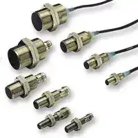
## **Cylindrical Proximity Sensor E2A**

## _High quality for extra long life in daily use_

- wide portfolio range through modular concept

- designed and tested for extra long life

- IP67 and IP69k for highest protection in wet environments

- continuously high quality level through specialized manufacturing process

- DC 3-wire and DC 2-wire models

- Normally open (NO), normally closed (NC) and antivalent (NO+NC) models

- up to 30mm sensing distance

- Stainless steel and brass housings

- Pre-wired versions with different cable materials and diameters, M8 and M12 connector types, pre-wired types with cable end connectors

## Ordering Information

DC 3-wire models (NO + NC: DC 4-wire)[*2]

**Thread Size distanceSensing Connec-tion materialBody (overall length Output confiOperation mode NO Operation mode NC guration length)** PNP E2A-S08KS02-WP-B1 2M E2A-S08KS02-WP-B2 2M 27 (40) NPN E2A-S08KS02-WP-C1 2M E2A-S08KS02-WP-C2 2M ~~pit~~ Pre-wired ~~ttf |}~~ PNP E2A-S08LS02-WP-B1 2M E2A-S08LS02-WP-B2 2M 49 (62) NPN E2A-S08LS02-WP-C1 2M E2A-S08LS02-WP-C2 2M ~~_ ee~~ PNP E2A-S08KS02-M1-B1 E2A-S08KS02-M1-B2 27 (43) M12 NPN E2A-S08KS02-M1-C1 E2A-S08KS02-M1-C2 connector PNP E2A-S08LS02-M1-B1 E2A-S08LS02-M1-B2 49 (65) Shiel2.0 mm ~~_ ———————[———————]~~ NPN E2A-S08LS02-M1-C1 E2A-S08LS02-M1-C2 ded PNP E2A-S08KS02-M5-B1 E2A-S08KS02-M5-B2 M8 27 (39) NPN E2A-S08KS02-M5-C1 E2A-S08KS02-M5-C2 connector (3-pin) PNP E2A-S08LS02-M5-B1 E2A-S08LS02-M5-B2 49 (61) NPN E2A-S08LS02-M5-C1 E2A-S08LS02-M5-C2 ~~_ ——————E[———————]~~ PNP E2A-S08KS02-M3-B1 E2A-S08KS02-M3-B2 M8 27 (39) NPN E2A-S08KS02-M3-C1 E2A-S08KS02-M3-C2 connector (4-pin) PNP E2A-S08LS02-M3-B1 E2A-S08LS02-M3-B2 Stain49 (61) NPN E2A-S08LS02-M3-C1 E2A-S08LS02-M3-C2 M8 ~~_~~ less ~~———————[——————]~~ steel*1 ~~———————————~~ 27 (40) PNP E2A-S08KN04-WP-B1 2M E2A-S08KN04-WP-B2 2M NPN E2A-S08KN04-WP-C1 2M E2A-S08KN04-WP-C2 2M Pre-wired PNP E2A-S08LN04-WP-B1 2M E2A-S08LN04-WP-B2 2M ~~————————~~ 49 (62) NPN E2A-S08LN04-WP-C1 2M E2A-S08LN04-WP-C2 2M ~~— eH~~ PNP E2A-S08KN04-M1-B1 E2A-S08KN04-M1-B2 27 (43) M12 NPN E2A-S08KN04-M1-C1 E2A-S08KN04-M1-C2 connector PNP E2A-S08LN04-M1-B1 E2A-S08LN04-M1-B2 Non49 (65) NPN E2A-S08LN04-M1-C1 E2A-S08LN04-M1-C2 shiel4.0 mm ~~_ ———————~~ ded PNP E2A-S08KN04-M5-B1 E2A-S08KN04-M5-B2 M8 27 (39) NPN E2A-S08KN04-M5-C1 E2A-S08KN04-M5-C2 connector (3-pin) PNP E2A-S08LN04-M5-B1 E2A-S08LN04-M5-B2 49 (61) NPN E2A-S08LN04-M5-C1 E2A-S08LN04-M5-C2 ~~_ ———————[———————] ee~~ PNP E2A-S08KN04-M3-B1 E2A-S08KN04-M3-B2 M8 27 (39) NPN E2A-S08KN04-M3-C1 E2A-S08KN04-M3-C2 connector PNP E2A-S08LN04-M3-B1 E2A-S08LN04-M3-B2 (4 pin) 49 (61) NPN E2A-S08LN04-M3-C1 E2A-S08LN04-M3-C2 ~~_ ————————a~~

*1.

**E2A**

1

|**Size**|**Size**|**Sensing**<br>**distance**|**Connec-**<br>**tion**|**Body**<br>**material**|**Thread**<br>**length**<br>**(overall**<br>**length)**|**Output**<br>**confi-**<br>**guration**|**Operation mode NO**|**Operation mode NC**|**Operation mode NO + NC**|
|---|---|---|---|---|---|---|---|---|---|
|M12|Shiel-<br>ded|4.0 mm|Pre-wired|Brass*3|34 (50)|PNP|E2A-M12KS04-WP-B1 2M|E2A-M12KS04-WP-B2 2M|E2A-M12KS04-WP-B3 2M|
|||||||NPN|E2A-M12KS04-WP-C1 2M|E2A-M12KS04-WP-C2 2M|E2A-M12KS04-WP-C3 2M|
||||||56 (72)|PNP|E2A-M12LS04-WP-B1 2M|E2A-M12LS04-WP-B2 2M|E2A-M12LS04-WP-B3 2M|
|||||||NPN|E2A-M12LS04-WP-C1 2M|E2A-M12LS04-WP-C2 2M|E2A-M12LS04-WP-C3 2M|
||||M12<br>connector|Brass*3|34 (48)|PNP|E2A-M12KS04-M1-B1|E2A-M12KS04-M1-B2|E2A-M12KS04-M1-B3|
|||||||NPN|E2A-M12KS04-M1-C1|E2A-M12KS04-M1-C2|E2A-M12KS04-M1-C3|
||||||56 (70)|PNP|E2A-M12LS04-M1-B1|E2A-M12LS04-M1-B2|E2A-M12LS04-M1-B3|
|||||||NPN|E2A-M12LS04-M1-C1|E2A-M12LS04-M1-C2|E2A-M12LS04-M1-C3|
||||M8<br>connector<br>(3-pin)|Brass*3|34 (48)|PNP|E2A-M12KS04-M5-B1|E2A-M12KS04-M5-B2|n.a.|
|||||||NPN|E2A-M12KS04-M5-C1|E2A-M12KS04-M5-C2|n.a.|
||||||56 (70)|PNP|E2A-M12LS04-M5-B1|E2A-M12LS04-M5-B2|n.a.|
|||||||NPN|E2A-M12LS04-M5-C1|E2A-M12LS04-M5-C2|n.a.|
||||M8<br>connector<br>(4-pin)|Brass*3|34 (48)|PNP|E2A-M12KS04-M3-B1|E2A-M12KS04-M3-B2|n.a.|
|||||||NPN|E2A-M12KS04-M3-C1|E2A-M12KS04-M3-C2|n.a.|
||||||56 (70)|PNP|E2A-M12LS04-M3-B1|E2A-M12LS04-M3-B2|n.a.|
|||||||NPN|E2A-M12LS04-M3-C1|E2A-M12LS04-M3-C2|n.a.|
||Non-<br>shiel-<br>ded|8.0 mm|Pre-wired|Brass*3|34 (50)|PNP|E2A-M12KN08-WP-B1 2M|E2A-M12KN08-WP-B2 2M|E2A-M12KN08-WP-B3 2M|
|||||||NPN|E2A-M12KN08-WP-C1 2M|E2A-M12KN08-WP-C2 2M|E2A-M12KN08-WP-C3 2M|
||||||56 (72)|PNP|E2A-M12LN08-WP-B1 2M|E2A-M12LN08-WP-B2 2M|E2A-M12LN08-WP-B3 2M|
|||||||NPN|E2A-M12LN08-WP-C1 2M|E2A-M12LN08-WP-C2 2M|E2A-M12LN08-WP-C3 2M|
||||M12<br>connector|Brass*3|34 (48)|PNP|E2A-M12KN08-M1-B1|E2A-M12KN08-M1-B2|E2A-M12KN08-M1-B3|
|||||||NPN|E2A-M12KN08-M1-C1|E2A-M12KN08-M1-C2|E2A-M12KS08-M1-C3|
||||||56 (70)|PNP|E2A-M12LN08-M1-B1|E2A-M12LN08-M1-B2|E2A-M12LS08-M1-B3|
|||||||NPN|E2A-M12LN08-M1-C1|E2A-M12LN08-M1-C2|E2A-M12LS08-M1-C3|
||||M8<br>connector<br>(3-pin)|Brass*3|34 (48)|PNP|E2A-M12KN08-M5-B1|E2A-M12KN08-M5-B2|n.a.|
|||||||NPN|E2A-M12KN08-M5-C1|E2A-M12KN08-M5-C2|n.a.|
||||||56 (70)|PNP|E2A-M12LN08-M5-B1|E2A-M12LN08-M5-B2|n.a.|
|||||||NPN|E2A-M12LN08-M5-C1|E2A-M12LN08-M5-C2|n.a.|
||||M8<br>connector<br>(4-pin)|Brass*3|34 (48)|PNP|E2A-M12KN08-M3-B1|E2A-M12KN08-M3-B2|n.a.|
|||||||NPN|E2A-M12KN08-M3-C1|E2A-M12KN08-M3-C2|n.a.|
||||||56 (70)|PNP|E2A-M12LN08-M3-B1|E2A-M12LN08-M3-B2|n.a.|
|||||||NPN|E2A-M12LN08-M3-C1|E2A-M12LN08-M3-C2|n.a.|
|M18|Shiel-<br>ded|8.0 mm|Pre-wired|Brass*3|39 (59)|PNP|E2A-M18KS08-WP-B1 2M|E2A-M18KS08-WP-B2 2M|E2A-M18KS08-WP-B3 2M|
|||||||NPN|E2A-M18KS08-WP-C1 2M|E2A-M18KS08-WP-C2 2M|E2A-M18KS08-WP-C3 2M|
||||||61 (81)|PNP|E2A-M18LS08-WP-B1 2M|E2A-M18LS08-WP-B2 2M|E2A-M18LS08-WP-B3 2M|
|||||||NPN|E2A-M18LS08-WP-C1 2M|E2A-M18LS08-WP-C2 2M|E2A-M18LS08-WP-C3 2M|
||||M12<br>connector|Brass*3|39 (53)|PNP|E2A-M18KS08-M1-B1|E2A-M18KS08-M1-B2|E2A-M18KS08-M1-B3|
|||||||NPN|E2A-M18KS08-M1-C1|E2A-M18KS08-M1-C2|E2A-M18KS08-M1-C3|
||||||61 (75)|PNP|E2A-M18LS08-M1-B1|E2A-M18LS08-M1-B2|E2A-M18LS08-M1-B3|
|||||||NPN|E2A-M18LS08-M1-C1|E2A-M18LS08-M1-C2|E2A-M18LS08-M1-C3|
||||M8<br>connector<br>(3-pin)|Brass*3|39 (53)|PNP|E2A-M18KS08-M5-B1|E2A-M18KS08-M5-B2|n.a.|
|||||||NPN|E2A-M18KS08-M5-C1|E2A-M18KS08-M5-C2|n.a.|
||||||61 (75)|PNP|E2A-M18LS08-M5-B1|E2A-M18LS08-M5-B2|n.a.|
|||||||NPN|E2A-M18LS08-M5-C1|E2A-M18LS08-M5-C2|n.a.|
||||M8<br>connector<br>(4-pin)|Brass*3|39 (53)|PNP|E2A-M18KS08-M3-B1|E2A-M18KS08-M3-B2|n.a.|
|||||||NPN|E2A-M18KS08-M3-C1|E2A-M18KS08-M3-C2|n.a.|
||||||61 (75)|PNP|E2A-M18LS08-M3-B1|E2A-M18LS08-M3-B2|n.a.|
|||||||NPN|E2A-M18LS08-M3-C1|E2A-M18LS08-M3-C2|n.a.|
||Non-<br>shiel-<br>ded|16.0 mm|Pre-wired|Brass*3|39 (59)|PNP|E2A-M18KN16-WP-B1 2M|E2A-M18KN16-WP-B2 2M|E2A-M18KN16-WP-B3 2M|
|||||||NPN|E2A-M18KN16-WP-C1 2M|E2A-M18KN16-WP-C2 2M|E2A-M18KN16-WP-C3 2M|
||||||61 (81)|PNP|E2A-M18LN16-WP-B1 2M|E2A-M18LN16-WP-B2 2M|E2A-M18LN16-WP-B3 2M|
|||||||NPN|E2A-M18LN16-WP-C1 2M|E2A-M18LN16-WP-C2 2M|E2A-M18LN16-WP-C3 2M|
||||M12<br>connector|Brass*3|39 (53)|PNP|E2A-M18KN16-M1-B1|E2A-M18KN16-M1-B2|E2A-M18KN16-M1-B3|
|||||||NPN|E2A-M18KN16-M1-C1|E2A-M18KN16-M1-C2|E2A-M18KS16-M1-C3|
||||||61 (75)|PNP|E2A-M18LN16-M1-B1|E2A-M18LN16-M1-B2|E2A-M18LS16-M1-B3|
|||||||NPN|E2A-M18LN16-M1-C1|E2A-M18LN16-M1-C2|E2A-M18LS16-M1-C3|
||||M8<br>connector<br>(3-pin)|Brass*3|39 (53)|PNP|E2A-M18KN16-M5-B1|E2A-M18KN16-M5-B2|n.a.|
|||||||NPN|E2A-M18KN16-M5-C1|E2A-M18KN16-M5-C2|n.a.|
||||||61 (75)|PNP|E2A-M18LN16-M5-B1|E2A-M18LN16-M5-B2|n.a.|
|||||||NPN|E2A-M18LN16-M5-C1|E2A-M18LN16-M5-C2|n.a.|
||||M8<br>connector<br>(4-pin)|Brass*3|39 (53)|PNP|E2A-M18KN16-M3-B1|E2A-M18KN16-M3-B2|n.a.|
|||||||NPN|E2A-M18KN16-M3-C1|E2A-M18KN16-M3-C2|n.a.|
||||||61 (75)|PNP|E2A-M18LN16-M3-B1|E2A-M18LN16-M3-B2|n.a.|
|||||||NPN|E2A-M18LN16-M3-C1|E2A-M18LN16-M3-C2|n.a.|


Inductive Sensors

2

|**Size**|**Size**|**Sensing**<br>**distance**|**Connec-**<br>**tion**|**Body**<br>**material**|**Thread**<br>**length**<br>**(overall**<br>**length)**|**Output**<br>**confi-**<br>**guration**|**Operation mode NO**|**Operation mode NC**|**Operation mode NO + NC**|
|---|---|---|---|---|---|---|---|---|---|
|M30|Shiel-<br>ded|15.0 mm|Pre-wired|Brass*3|44 (64)|PNP|E2A-M30KS15-WP-B1 2M|E2A-M30KS15-WP-B2 2M|E2A-M30KS15-WP-B3 2M|
|||||||NPN|E2A-M30KS15-WP-C1 2M|E2A-M30KS15-WP-C2 2M|E2A-M30KS15-WP-C3 2M|
||||||66 (86)|PNP|E2A-M30LS15-WP-B1 2M|E2A-M30LS15-WP-B2 2M|E2A-M30LS15-WP-B3 2M|
|||||||NPN|E2A-M30LS15-WP-C1 2M|E2A-M30LS15-WP-C2 2M|E2A-M30LS15-WP-C3 2M|
||||M12<br>connector|Brass*3|44 (58)|PNP|E2A-M30KS15-M1-B1|E2A-M30KS15-M1-B2|E2A-M30KS15-M1-B3|
|||||||NPN|E2A-M30KS15-M1-C1|E2A-M30KS15-M1-C2|E2A-M30KS15-M1-C3|
||||||66 (80)|PNP|E2A-M30LS15-M1-B1|E2A-M30LS15-M1-B2|E2A-M30LS15-M1-B3|
|||||||NPN|E2A-M30LS15-M1-C1|E2A-M30LS15-M1-C2|E2A-M30LS15-M1-C3|
||||M8<br>connector<br>(3-pin)|Brass*3|44 (58)|PNP|E2A-M30KS15-M5-B1|E2A-M30KS15-M5-B2|n.a.|
|||||||NPN|E2A-M30KS15-M5-C1|E2A-M30KS15-M5-C2|n.a.|
||||||66 (80)|PNP|E2A-M30LS15-M5-B1|E2A-M30LS15-M5-B2|n.a.|
|||||||NPN|E2A-M30LS15-M5-C1|E2A-M30LS15-M5-C2|n.a.|
||||M8<br>connector<br>(4-pin)|Brass*3|44 (58)|PNP|E2A-M30KS15-M3-B1|E2A-M30KS15-M3-B2|n.a.|
|||||||NPN|E2A-M30KS15-M3-C1|E2A-M30KS15-M3-C2|n.a.|
||||||66 (80)|PNP|E2A-M30LS15-M3-B1|E2A-M30LS15-M3-B2|n.a.|
|||||||NPN|E2A-M30LS15-M3-C1|E2A-M30LS15-M3-C2|n.a.|
||Non-<br>shiel-<br>ded|20.0 mm|Pre-wired|Brass*3|44 (64)<br>(See<br>note.)|PNP|E2A-M30KN20-WP-B1 2M|E2A-M30KN20-WP-B2 2M|E2A-M30KN20-WP-B3 2M|
|||||||NPN|E2A-M30KN20-WP-C1 2M|E2A-M30KN20-WP-C2 2M|E2A-M30KN20-WP-C3 2M|
|||30.0 mm|||66 (86)|PNP|E2A-M30LN30-WP-B1 2M|E2A-M30LN30-WP-B2 2M|E2A-M30LN30-WP-B3 2M|
|||||||NPN|E2A-M30LN30-WP-C1 2M|E2A-M30LN30-WP-C2 2M|E2A-M30LN30-WP-C3 2M|
|||20.0 mm|M12<br>connector|Brass*3|44 (58)<br>(See<br>note.)|PNP|E2A-M30KN20-M1-B1|E2A-M30KN20-M1-B2|E2A-M30KN20-M1-B3|
|||||||NPN|E2A-M30KN20-M1-C1|E2A-M30KN20-M1-C2|E2A-M30KN20-M1-C3|
|||30.0 mm|||66 (80)|PNP|E2A-M30LN30-M1-B1|E2A-M30LN30-M1-B2|E2A-M30LN30-M1-B3|
|||||||NPN|E2A-M30LN30-M1-C1|E2A-M30LN30-M1-C2|E2A-M30LN30-M1-C3|
|||20.0 mm|M8<br>connector<br>(3-pin)|Brass*3|44 (58)<br>(See<br>note.)|PNP|E2A-M30KN20-M5-B1|E2A-M30KN20-M5-B2|n.a.|
|||||||NPN|E2A-M30KN20-M5-C1|E2A-M30KN20-M5-C2|n.a.|
|||30.0 mm|||66 (80)|PNP|E2A-M30LN30-M5-B1|E2A-M30LN30-M5-B2|n.a.|
|||||||NPN|E2A-M30LN30-M5-C1|E2A-M30LN30-M5-C2|n.a.|
|||20.0 mm|M8<br>connector<br>(4-pin)|Brass*3|44 (58)<br>(See<br>note.)|PNP|E2A-M30KN20-M3-B1|E2A-M30KN20-M3-B2|n.a.|
|||||||NPN|E2A-M30KN20-M3-C1|E2A-M30KN20-M3-C2|n.a.|
|||30.0 mm|||66 (80)|PNP|E2A-M30LN30-M3-B1|E2A-M30LN30-M3-B2|n.a.|
|||||||NPN|E2A-M30LN30-M3-C1|E2A-M30LN30-M3-C2|n.a.|


*1. Material specifications for stainless steel housing case: 1.4305 (W.-No.), SUS 303 (AISI), 2346 (SS). Please contact your OMRON representative for other stainless steel materials.

- *2. Please contact your OMRON representative for DC 2-wire models.

- *3. Stainless steel models are also available. Please contact your OMRON representative.

**Note:** M30 non-shielded Models with double sensing distance and short barrels cannot be mounted due to the necessary separation distance from the surrounding metal. Standard sensing models are thus available.

**E2A**

3

Connectivity

The E2A sensors are available with the following connectors and cable materials: Pre-wired models

Pre-wired models with cable end connectors

Standard cable lengths are 2m and 5m. For other cable lengths please contact your OMRON representative.

|representative.||
|---|---|
|Standard cable material: PVC (dia 4mm)|-WP|
|Other available cable materials and sizes:||
|- PVC (dia 6mm)|-WS|
|- PUR/PVC – PUR jacket (dia 4mm)|-WA|
|- PUR/PVC – PUR jacket (dia 6mm)<br>- PVC robotic cable (dia 4mm)|-WB<br>-WR|


|Pre-wired models with cable end connectors<br>DeyD|Pre-wired models with cable end connectors<br>DeyD|
|---|---|
|All pre-wired models can be fitted with cable and connectors.||
|Standard cable end connectors:||
|- M12|M1J|
|- M8 (4 pin)|M3J|
|- M8 (3 pin)|M5J|
|Other cable end connectors are available on request.||


Connector models

Standard connectors: M12, M8 (4 or 3 pin) -M1, -M3, -M5

Inductive Sensors

4

## Model Number Legend

## **E2A** @ **-** @@@@@ **-** @ **-** @@ **-** @@

**1 2 3 4 5 6 7 8 9 10 11 12 Example:** E2A-M12LS04-M1-B1 Standard, M12, long barrel, shielded, Sn=4 mm, M12 connector, PNP-NO E2A-S08KN04-WP-B1 5M Standard, M8 stainless steel, short barrel, non-shielded, Sn=4 mm, pre-wired PVC cable, PNP-NO, cable length=5 m

## **1. Basic name**

## **8. Kind of connection**

E2A WP: pre-wired, PVC, dia 4mm (standard) **2. Sensing technology** WS: pre-wired, PVC, dia 6mm Blank: Standard double distance WR: pre-wired, PVC, robotic cable, dia 4mm **3. Housing shape and material** WA: pre-wired, PUR/PVC (PUR jacket), dia 4mm M: Cylindrical, metric threaded, brass WB: pre-wired, PUR/PVC (PUR jacket), dia 6mm S: Cylindrical, metric threaded, stainless steel **4. Housing size** M1: M12 connector (4 pin) * 08: 8 mm M3: M8 connector (4 pin) 12: 12 mm M5: M8 connector (3 pin) 18: 18 mm 30: 30 mm M1J pre-wired with M12 cable end connector (4 pin) **5. Barrel length** M3J pre-wired with M8 cable end connector (4 pin) K: Standard length M5J pre-wired with M8 cable end connector (3 pin) L: Long body **9. Power source and output 6. Shield** B: DC, 3-wire, PNP open collector S: Shielded C: DC, 3-wire, NPN open collector N: Non-shielded D: DC, 2-wire **7. Sensing distance** E: DC, 3-wire, NPN voltage output Numeral: Sensing distance: e.g. 02=2 mm, 16=16 mm F: DC, 3-wire, PNP voltage output **10.Operation mode** 1: Normally open (NO) 2: Normally closed (NC) 3: Antivalent (NO+NC)

## **11.Specials (e.g., cable material, oscillating frequency)**

## **12.Cable length**

Blank: Connector type Numeral: Cable length

Note: *In case of DC 2-wire models the M12 connector identifier is '-M1G'

**E2A**

5

Specifications

## DC 3-wire Models / DC 4-wire (NO+NC)

|**Size**|**Size**|**M8**|**M8**|**M12**|**M12**|
|---|---|---|---|---|---|
|**Type**||**Shielded**|**Non-shielded**|**Shielded**|**Non-shielded**|
||**Item**|**E2A-S08**@**S02-**@@**-B1**<br>**E2A-S08**@**S02-**@@**-C1**|**E2A-S08**@**N04-**@@**-B1**<br>**E2A-S08**@**N04-**@@**-C1**|**E2A-M12**@**S04-**@@**-B**@<br>**E2A-M12**@**S04-**@@**-C**@<br>**E2A-S12**@**S04-**@@**-B**@<br>**E2A-S12**@**S04-**@@**-C**@|**E2A-M12**@**N08-**@@**-B**@<br>**E2A-M12**@**N08-**@@**-C**@<br>**E2A-S12**@**N08-**@@**-B**@<br>**E2A-S12**@**N08-**@@**-C**@|
|Sensingdistance||2 mm±10%|4 mm±10%|4 mm±10%|8 mm±10%|
|Settingdistance||0 to 1.6 mm|0 to 3.2 mm|0 to 3.2 mm|0 to 6.4 mm|
|Differential travel||10% max. of sensingdistance||||
|Target||Ferrous metal (The sensingdistance decreases with non-ferrous metal.)||||
|Standard target (mild steel ST37)||8×8×1 mm|12×12×1 mm|12×12×1 mm|24×24×1 mm|
|Response frequency (See note 1.)||1,500 Hz|1,000 Hz|1,000 Hz|800 Hz|
|Power supply voltage<br>(operatingvoltage range)||12 to 24 VDC. Ripple (p-p): 10% max.<br>(10 to 32 VDC)||||
|Current consumption (DC 3-wire)||10 mA max.||||
|Output type||-B models: PNP open collector<br>-C models: NPN open collector||||
|Control<br>output|Load current<br>(See note 2.)|200 mA max. (32 VDC max.)||||
||Residual voltage|2 V max. (under load current of 200 mA with cable length of 2 m)||||
|Indicator||Operation indicator (Yellow LED)||||
|Operation mode<br>(with sensing object approaching)||-B1/-C1 models: NO<br>-B2/-C2 models: NC<br>-B3/ -C3 models: NO+NC<br>For details, refer to the timingcharts. (See note 4.)||||
|Protection circuit||Power source circuit reverse polarity protection,<br>Surge suppressor, Short-circuit protection||Output reverse polarity protection, Power source<br>circuit reverse polarity protection, Surge suppres-<br>sor, Short-circuit protection||
|Ambient air temperature||Operating:−40°C to 70°C, Storage:−40°C to 85°C (with no icingor condensation)||||
|Temperature influence (See note 2.)||±10% max. of sensing distance at 23°C within temperature range of−25°C to 70°C<br>±15% max. of sensingdistance at 23°C within temperature range of−40°C to 70°C||||
|Ambient humidity||Operating: 35% to 95%, Storage: 35% to 95%||||
|Voltage influence||±1% max. of sensingdistance in rated voltage range±15%||||
|Insulation resistance||50 MΩmin. (at 500 VDC) between current carryparts and case||||
|Dielectric strength||1,000 VAC at 50/60 Hz for 1 min between current carryparts and case||||
|Vibration resistance||10 to 55 Hz, 1.5-mm double amplitude for 2 hours each in X, Y and Z directions||||
|Shock resistance||500 m/s2, 10 times each in X, Y and Z directions||1,000 m/s2, 10 times each in X, Y and Z directions||
|Standard and listings (See note 3.)||IP67 after IEC 60529<br>IP69k after DIN 40050<br>EMC after EN60947-5-2||||
|Connection method||Pre-wired models (standard is dia 4mm PVC cable with length = 2m).<br>Please see chapter 'Connectivity' for details on different cable materials and lenghts and M8 or M12<br>connectors.||||
|Weight<br>(packaged)|Pre-wired model|Approx. 65g||Approx. 85g||
||Connector model|M12 connector models: Approx. 20 g<br>M8 connector models: Approx. 15g||Approx. 35 g||
|Material|Case|Stainless steel||Brass-nickel plated or stainless steel||
||Sensingsurface|PBT||||
||Cable|Standard cable is PVC dia 4mm.<br>For other cable materials or diameters please refer to chapter 'Connectivity'||||
||Clamping nut|Brass-nickel plated||Brass-nickel plated for brass models stainless<br>steel for steel models||


**Note 1.** The response frequency is an average value. Measurement conditions are as follows: standard target, a distance of twice the standard target distance between targets, and a setting distance of half the sensing distance.

**2.** When using any model at an ambient temperature between −40°C and −25°C and a power voltage between 30 and 32 VDC, use a load current of 100 mA max.,

**3.** For USA and Canada: use class 2 circuit only.

**4.** -B3/ -C3 NO+NC models are available in M12, M18 and M30 housings with M12 connectors, pre-wired and with cable end connectors.

Inductive Sensors

6

DC 3-wire Models / DC 4-wire (NO+NC)

|**Size**|**Size**|**M18**|**M18**|**M30**|**M30**|**M30**|
|---|---|---|---|---|---|---|
|**Type**||**Shielded**|**Non-shielded**|**Shielded**|**Non-shielded**|**Non-shielded**|
||**Item**|**E2A-M18**@**S08-**@@**-B**@<br>**E2A-M18**@**S08-**@@**-C**@<br>**E2A-S18**@**S08-**@@**-B**@<br>**E2A-S18**@**S08-**@@**-C**@|**E2A-M18**@**N16-**@@**-B**@<br>**E2A-M18**@**N16-**@@**-C**@<br>**E2A-S18**@**N16-**@@**-B**@<br>**E2A-S18**@**N16-**@@**-C**@|**E2A-M30**@**S15-**@@**-B**@<br>**E2A-M30**@**S15-**@@**-C**@<br>**E2A-S30**@**S15-**@@**-B**@<br>**E2A-S30**@**S15-**@@**-C**@|**E2A-M30KN20-**@@**-B**@<br>**E2A-M30KN20-**@@**-C**@<br>**E2A-S30KN20-**@@**-B**@<br>**E2A-S30KN20-**@@**-C**@|**E2A-M30LN30-**@@**-B**@<br>**E2A-M30LN30-**@@**-C**@<br>**E2A-S30LN30-**@@**-B**@<br>**E2A-S30LN30-**@@**-C**@|
|Sensingdistance||8 mm±10%|16 mm±10%|15 mm±10%|20 mm±10%|30 mm±10%|
|Settingdistance||0 to 6.4 mm|0 to 12.8 mm|0 to 12 mm|0 to 16 mm|0 to 24 mm|
|Differential travel||10% max. of sensingdistance|||||
|Target||Ferrous metal (The sensingdistance decreases with non-ferrous metal.)|||||
|Standard target<br>(mild steel ST37)||24×24×1 mm|48×48×1 mm|45×45×1 mm|60×60×1 mm|90×90×1 mm|
|Response frequency<br>(See note 1.)||500 Hz|400 Hz|250 Hz|100 Hz|100 Hz|
|Power supply voltage<br>(operatingvoltage range)||12 to 24 VDC. Ripple (p-p): 10% max.<br>(10 to 32 VDC)|||||
|Current consumption<br>(DC 3-wire)||10 mA max.|||||
|Output type||-B models: PNP open collector<br>-C models: NPN open collector|||||
|Control<br>output|Load current<br>(See note 2.)|200 mA max. (32 VDC max.)|||||
||Residual voltage|2 V max. (under load current of 200 mA with cable length of 2 m)|||||
|Indicator||Operation indicator (Yellow LED)|||||
|Operation mode<br>(with sensing object<br>approaching)||-B1/-C1 models: NO<br>-B2/-C2 models: NC<br>-B3/ -C3 models: NO+NC<br>For details, refer to the timingcharts.|||||
|Protection circuit||Output reverse polarity protection, Power source circuit reverse polarity protection, Surge suppressor,<br>Short-circuit protection|||||
|Ambient air temperature||Operating:−40°C to 70°C, Storage:−40°C to 85°C (with no icingor condensation)|||||
|Temperature influence<br>(See note 2.)||±10% max. of sensing distance at 23°C within temperature range of−25°C to 70°C<br>±15% max. of sensingdistance at 23°C within temperature range of−40°C to 70°C|||||
|Ambient humidity||Operating: 35% to 95%, Storage: 35% to 95%|||||
|Voltage influence||±1% max. of sensingdistance in rated voltage range±15%|||||
|Insulation resistance||50 MΩmin. (at 500 VDC) between current carryparts and case|||||
|Dielectric strength||1,000 VAC at 50/60 Hz for 1 min between current carry parts and case|||||
|Vibration resistance||10 to 55 Hz, 1.5-mm double amplitude for 2 hours each in X, Y and Z directions|||||
|Shock resistance||1,000 m/s2, 10 times each in X, Y and Z directions|||||
|Standard and listings (See<br>note 3.)||IP67 after IEC 60529<br>IP69k after DIN 40050<br>EMC after EN60947-5-2|||||
|Connection method||Pre-wired models (standard is dia 4mm PVC cable with length = 2m).<br>Please see chapter 'Connectivity' for details on different cable materials and lenghts and M8 or M12 connectors.|||||
|Weight<br>(pak-<br>kaged)|Pre-wired model|Approx. 160g||Approx. 280g|Approx. 280g|Approx. 370g|
||Connector model|Approx. 70 g||Approx. 200 g|Approx. 200 g|Approx. 260 g|
|Material|Case|Brass-nickel plated or stainless steel|||||
||Sensingsurface|PBT|||||
||Cable|Standard cable is PVC dia 4mm. For other cable materials or diameters please refer to chapter 'Connectivity'|||||
||Clampingnut|brass-nickel plated for brass models stainless steel for steel models|||||


**Note 1.** The response frequency is an average value. Measurement conditions are as follows: standard target, a distance of twice the standard target distance between targets, and a setting distance of half the sensing distance.

**2.** When using any model at an ambient temperature between −40°C and −25°C and a power voltage between 30 and 32 VDC, use a load current of 100 mA max.

**3.** For USA and Canada: use class 2 circuit only.

**E2A**

7

## DC 2-wire Models

|**Size**|**Size**|**M8**|**M8**|**M12**|**M12**|
|---|---|---|---|---|---|
|**Type**||**Shielded**|**Non-shielded**|**Shielded**|**Non-shielded**|
||**Item**|**E2A-S08**@**S02-D**@|**E2A-S08**@**N04-D**@|**E2A-M12**@**S04-D**@<br>**E2A-S12**@**S04-D**@|**E2A-M12**@**N08-D**@<br>**E2A-S12**@**N08-D**@|
|Sensingdistance||2 mm±10%|4 mm±10%|4 mm±10%|8 mm±10%|
|Settingdistance||0 to 1.6 mm|0 to 3.2 mm|0 to 3.2 mm|0 to 6.4 mm|
|Differential travel||10% max. of sensingdistance||||
|Target||Ferrous metal (The sensingdistance decreases with non-ferrous metal.)||||
|Standard target||8×8×1 mm|12×12×1 mm|12×12×1 mm|24×24×1 mm|
|Response frequency(See note 1.)||1,500 Hz|1,000 Hz|1,000 Hz|800 Hz|
|Power supply voltage<br>(operatingvoltage range)||12 to 24 VDC. Ripple (p-p): 10% max.<br>(10 to 32 VDC)||||
|Leakage current||0.8 mA max.||||
|Output type||DC 2 wire type||||
|Control<br>output|Load current<br>(See note 2.)|3 to 100 mA||||
||Residual voltage|3 V max. (under load current of 100 mA with cable length of 2 m)||||
|Indicator (see timing chart)||NO type: Operation indicator (Yellow), Setting indicator (Red)<br>NC type: Operation indicator (Yellow)||||
|Operation mode||-D1 models: NO<br>-D2 models: NC||||
|Protection circuit||Surget suppressor, Short circuit protection||||
|Ambient temperature||Operating:−40°C to 70°C, Storage:−40°C to 85°C (with no icingor condensation)||||
|Temperature influence||±10% max. of sensing distance at 23°C within temperature range of−25°C to 70°C<br>±15% max. of sensingdistance at 23°C within temperature range of−40°C to 70°C||||
|Ambient humidity||Operating: 35% to 95%, Storage: 35% to 95%||||
|Voltage influence||±1% max. of sensingdistance in rated voltage range±15%||||
|Insulation resistance||50 MΩmin. (at 500 VDC) between current carryparts and case||||
|Dielectric strength||1,000 VAC at 50/60 Hz for 1 min between current carryparts and case||||
|Vibration resistance||10 to 55 Hz, 1.5-mm double amplitude for 2 hours each in X, Y and Z directions||||
|Shock resistance||500 m/s2, 10 times each in X, Y and Z directions||1,000 m/s2, 10 times each in X, Y and Z directions||
|Standard and listings (See note 3.)||IP67 after IEC 60529<br>IP69k after DIN 40050<br>EMC after EN60947-5-2||||
|Connection method||Pre-wired models (standard is dia 4mm PVC cable with length = 2m).<br>Please see chapter 'Connectivity' for details on different cable materials and lenghts and M8 or M12<br>connectors.||||
|Weight<br>(packaged)|Pre-wired model|Approx. 65g||Approx. 85g||
||Connector model|M12 connector models: Approx. 20 g<br>M8 connector models: Approx. 15g||Approx. 35 g||
|Material|Case|Stainless steel||Brass-nickel plated or stainless steel||
||Sensingsurface|PBT||||
||Cable|Standard cable is PVC dia 4mm.<br>For other cable materials or diameters please refer to chapter 'Connectivity'||||
||Clamping nut|Brass-nickel plated||Brass-nickel plated for brass models stainless<br>steel for steel models||


**Note 1.** The response frequency is an average value. Measurement conditions are as follows: standard target, a distance of twice the standard target distance between targets, and a setting distance of half the sensing distance.

**2.** When using any model at an ambient temperature between −40°C and −25°C and a power voltage between 30 and 32 VDC, use a load current of 50 mA max.

**3.** For USA and Canada: use class 2 circuit only.

Inductive Sensors

8

## DC 2-wire Models

|**Size**|**Size**|**M18**|**M18**|**M30**|**M30**|
|---|---|---|---|---|---|
|**Type**||**Shielded**|**Non-shielded**|**Shielded**|**Non-shielded**|
||**Item**|**E2A-M18**@**S08-D**@<br>E2A-S18@S08-D@|**E2A-M18**@**N16-D**@<br>E2A-S18@N16-D@|**E2A-M30**@**S15-D**@<br>**E2A-S30**@**S15-D**@|**E2A-M30**@**N30-D**@<br>**E2A-M30**@**N20-D**@<br>**E2A-S30**@**N30-D**@<br>**E2A-S30**@**N20-D**@|
|Sensing distance||8 mm±10%|16 mm±10%|15 mm±10%|Short body: 20 m±10%<br>Longbody: 30 m±10%|
|Setting distance||0 to 6.4 mm|0 to 12.8 mm|0 to 12 mm|Short body: 0 to 16 mm<br>Longbody: 0 to 24 mm|
|Differential travel||10% max. of sensingdistance||||
|Target||Ferrous metal (The sensingdistance decreases with non-ferrous metal.)||||
|Standard target||24x24x1 mm|48x48x1 mm|45x45x1 mm|Short body: 60x60x1 mm<br>Longbody: 90x90x1mm|
|Response frequency(See note 1.)||500 Hz|400 Hz|250 Hz|100 Hz|
|Power supply voltage<br>(operatingvoltage range)||12 to 24 VDC. Ripple (p-p): 10% max.<br>(10 to 32 VDC)||||
|Leakage current||0.8 mA max.||||
|Output type||DC 2 wire type||||
|Control<br>output|Load current<br>(See note 2.)|3 to 100 mA||||
||Residual voltage|3 V max. (under load current of 100 mA with cable length of 2 m)||||
|Indicator (see timing chart)||NO type: Operation indicator (Yellow), Setting indicator (Red)<br>NC type: Operation indicator (Yellow)||||
|Operation mode||-D1 models: NO<br>-D2 models: NC||||
|Protection circuit||Surget suppressor, Short circuit protection||||
|Ambient temperature||Operating:−40°C to 70°C, Storage:−40°C to 85°C (with no icingor condensation)||||
|Temperature influence||±10% max. of sensing distance at 23°C within temperature range of−25°C to 70°C<br>±15% max. of sensingdistance at 23°C within temperature range of−40°C to 70°C||||
|Ambient humidity||Operating: 35% to 95%, Storage: 35% to 95%||||
|Voltage influence||±1% max. of sensingdistance in rated voltage range±15%||||
|Insulation resistance||50 MΩmin. (at 500 VDC) between current carry parts and case||||
|Dielectric strength||1,000 VAC at 50/60 Hz for 1 min between current carryparts and case||||
|Vibration resistance||10 to 55 Hz, 1.5-mm double amplitude for 2 hours each in X, Y and Z directions||||
|Shock resistance||500 m/s2, 10 times each in X, Y and Z directions||||
|Standard and listings (See note 3.)||IP67 after IEC 60529<br>IP69k after DIN 40050<br>EMC after EN60947-5-2||||
|Connection method||Pre-wired models (standard is dia 4mm PVC cable with length = 2m).<br>Please see chapter 'Connectivity' for details on different cable materials and lenghts and M8 or M12<br>connectors.||||
|Weight<br>(packaged)|Pre-wired model|Approx. 160 g||Approx. 280 g|short body:<br>280 g<br>longbody:<br>370g|
||Connector model|Approx. 70 g||Approx. 200 g|short body:<br>200 g<br>longbody:<br>260g|
|Material|Case|Brass-nickel plated or stainless steel||||
||Sensingsurface|PBT||||
||Cable|Standard cable is PVC dia 4mm.<br>For other cable materials or diameters please refer to chapter 'Connectivity'||||
||Clampingnut|brass-nickel plated for brass models stainless steel for steel models||||


**Note 1.** The response frequency is an average value. Measurement conditions are as follows: standard target, a distance of twice the standard target distance between targets, and a setting distance of half the sensing distance.

**2.** When using any model at an ambient temperature between -40°C and -25°C and a power voltage between 30 and 32 VDC, use a load current of 50 mA max.

**3.** For USA and Canada: use class 2 circuit only.

**E2A**

9

Engineering Data

## Operating Range (Typical)

**==> picture [335 x 173] intentionally omitted <==**

**----- Start of picture text -----**<br>
Shielded Models Non-shielded Models<br>18 35<br>E2A-M30LN30<br>16 E2A-M30@S15<br>30<br>14 Y<br>12 Y 25 X E2A-M30KN20<br>X<br>10 E2A-M18@S08 20<br>E2A-M18@N16<br>8 15<br>6 E2A-M12@S04 E2A-M12@N08<br>E2A-S08@S02/  10<br>4 E2A-M08@S02 E2A-M08E2A-S08@@N04/ N04<br>5<br>2<br>0−30  −20  −10  0  10  20  30 0−50 −40  −30  −20  −10  0  10  20  30  40  50<br>Distance Y (mm) Distance Y (mm)<br>Sensing distance X (mm) Sensing distance X (mm)<br>**----- End of picture text -----**<br>


## Influence of Sensing Object Size and Materials Shielded Models

**==> picture [489 x 340] intentionally omitted <==**

**----- Start of picture text -----**<br>
E2A-S08 @ S02 E2A-M12 @ S04/ E2A-S12 @ S04 E2A-M18 @ S08/E2A-S18 @ S08<br>2.5 5.0 8.0<br>@d t = 1 mm @d t = 1 mm Iron<br>X Iron X Iron 7.0<br>2.0 4.0<br>6.0 Stainless steel (SUS303)<br>Stainless steel<br>Stainless steel (SUS303) (SUS303)<br>5.0<br>1.5 3.0<br>Brass<br>Brass 4.0<br>Brass Aluminum<br>Aluminum<br>1.0 Aluminum 2.0 3.0<br>Copper Copper<br>Copper 2.0 @d t = 1 mm<br>0.5 1.0 X<br>1.0<br>0  5  10  15  20  25 0 5 10 15 20 25 30 35 0 10 20 30 40 50 60<br>Side length of sensing object d (mm) Side length of sensing object d (mm) Side length of sensing object d (mm)<br>E2A-M30 @ S15/ E2A-S30 @ S15<br>20<br>@d<br>t = 1 mm<br>X<br>16<br>Iron<br>12<br>Stainless steel (SUS303)<br>8 Brass<br>Aluminum<br>Copper<br>4<br>0 10 20 30 40 50 60 70 80<br>Side length of sensing object d (mm)<br>Sensing distance X (mm) Sensing distance X (mm) Sensing distance X (mm)<br>Sensing distance X (mm)<br>**----- End of picture text -----**<br>


Inductive Sensors

10

## Non-shielded Models

**==> picture [489 x 349] intentionally omitted <==**

**----- Start of picture text -----**<br>
E2A-S08 @ N04 E2A-M12 @ N08/E2A-S12 @ N08 E2A-M18 @ N16/E2A-S18 @N16<br>5.0 10 20<br>@d X t = 1 mm Iron @d X t = 1 mm Iron @d X t = 1 mm Iron<br>4.0 8 16<br>3.0 Stainless steel (SUS303) 6 12<br>Stainless steel (SUS303)<br>Stainless steel (SUS303)<br>2.0 Brass 4 8 Brass<br>Aluminum Brass Aluminum<br>Copper Aluminum Copper<br>1.0 2 Copper 4<br>0  10  20  30  40  50 0 10 20 30 40 50 0 20 40 60 80<br>Side length of sensing object d (mm) Side length of sensing object d (mm) Side length of sensing object d (mm)<br>E2A-M30KN20/E2A-S30KN20 E2A-M30LN30/E2A-S30LN30<br>25 35<br>@d @d<br>X t = 1 mm 30 X t = 1 mm Iron<br>Iron<br>20<br>25<br>Stainless steel (SUS303)<br>15 20<br>Stainless steel (SUS303)<br>Brass<br>15<br>10 Brass Aluminum<br>Aluminum Copper<br>Copper 10<br>5<br>5<br>0  20  40  60  80  100 0 20 40 60 80 100<br>Side length of sensing object d (mm) Side length of sensing object d (mm)<br>Sensing distance X (mm) Sensing distance X (mm) Sensing distance X (mm)<br>Sensing distance X (mm) Sensing distance X (mm)<br>**----- End of picture text -----**<br>


**E2A**

11

Operation

## DC 3-wire models

## PNP Output

|Operation|Operation|Operation|Operation|Operation|Operation|Operation|Operation|Operation|Operation|Operation|Operation|Operation|
|---|---|---|---|---|---|---|---|---|---|---|---|---|
|DC 3-wire models<br>PNP Output|||||||||||||
|**Operation mode**|**Model**||**Timing chart**||||||**Output circuit**||||
|NO|E2A-@-@-B1|Sensing<br>object<br>(%)<br>100<br>0<br>Rated<br>sensing<br>distance<br>Sensing zone<br>Non-sensing zone<br> <br><br>O<br>O<br>O<br>O|||Proximity<br>Sensor<br>N<br>FF<br>N<br>FF<br>Yellow indicator<br>Control output|3<br>1<br>2<br>4<br>3<br>1<br>4<br>Load<br>Brown<br>Black<br>(See note 1.)<br>Blue<br>+V<br>0 V<br>**Note 1:** With M8 connector models, there is no output<br>reverse polarity protection diode.<br>M12 Connector<br>Pin Arrangement<br>(See note 2.)<br>M8 connector<br>(3 pin)<br>Pin Arrangement<br>M8 Connector<br>(4 pin)<br>Pin Arrangement<br>(See note 2.)<br>**Note 2:** Pin 2 of the M12 connector and M8 connector is not<br>used.<br>Proximity<br>Sensor<br>main<br>circuits<br>1<br>2<br>4<br>3|||||||
||||||||||||||
||||||||Proximi<br>Sensor<br>main<br>circuits||||||
||||||||||(Se<br>ty<br>||||
||||||||||||e note 1.)|Lo<br>Blue|
||||||||||||||
||||||||||||||
||||||||||||||
||||||||||||||
|NC|E2A-@-@-B2|||<br>|Proximity<br>Sensor<br>N<br>FF<br>N<br>FF<br>Yellow indicator<br>Control output|3<br>1<br>2<br>4<br>Load<br>Brown<br>Black<br>(See note 1.)<br>Blue<br>+V<br>0 V<br>**Note 1:** With M8 connector models, there is no output<br>reverse polarity protection diode.<br>M12 Connector<br>Pin Arrangement<br>(See note 2.)<br>3<br>1<br>4<br>M8 connector<br>(3 pin)<br>Pin Arrangement<br>**Note 2:** Pin 4 of the M12 connector and M8 connector is not<br>used.<br>Proximity<br>Sensor<br>main<br>circuits<br>(M8 connector:      )<br>M8 Connector<br>(4 pin)<br>Pin Arrangement<br>(See note 2.)<br>1<br>2<br>4<br>3|||||||
||||Non-sensing zone||||||||||
||||Sensing<br>object||||||||||
||||(%)<br>1<br>sensing<br>distance||||||||||
||||||||||||||
||||||||||||||
||||||||||||||
||||||||||||||
||||||||||||||
|NO + NC|E2A-@-@-B3|Sensing<br>object<br>(%)<br>100<br>0<br>Rated<br>sensing<br>distance<br>Sensing zone<br>Non-sensing zone<br> <br><br>O<br>O<br>O<br>O<br>O<br>O|||Proximity<br>Sensor<br>N<br>FF<br>N<br>FF<br>Yellow indicator<br>NO output<br>NC output<br>N<br>FF|3<br>1<br>2<br>4<br>M12 Connector<br>Pin Arrangement<br>Proximity<br>Sensor<br>main<br>circuits|||||Brown<br>+V<br>Black<br>NO output<br>White<br>Load<br>Blue<br>2<br>3<br>Load<br>NC output<br>4<br>1<br>0 V||
|||||||||mity<br>or<br> <br>its|||||
||||||||||||||
||||||||||||||
||||||||||||||
|||||||||||||Lo<br>Blue<br>3|
||||||||||||||
||||||||||||||
||||||||||||||


Inductive Sensors

12

## DC 3-wire models

NPN Output

**==> picture [512 x 645] intentionally omitted <==**

**----- Start of picture text -----**<br>
Operation mode Model Timing chart Output circuit<br>Non-sensing zone Sensing zone Brown<br>+V<br>Sensing<br>object Load<br>(%) 100 0 Proximity Sensor main  (See note 1.) Black<br>circuits<br>Blue<br>ON 0 V<br>Yellow indicator<br>OFF<br>NO E2A-@-@-C1 ON Note 1: With M8 connector models, there is no output<br>OFF Control output reverse polarity protection diode.<br>M8 Connector<br>M12 Connector  M8 connector  (4 pin)<br>Pin Arrangement  (3 pin) Pin Arrangement<br>(See note 2.) Pin Arrangement (See note 2.)<br>1 4 2 4<br>1 3<br>2 4 1 3<br>3<br>Note 2: Pin 2 of the M12 connector and M8 connector is not<br>used.<br>Non-sensing zone Sensing zone Brown<br>+V<br>Sensing<br>object Load<br>(%) 100 0 Proximity Sensor  (See note 1.) Black<br>main circuits (M8 connector:      )<br>Blue<br>ON 0 V<br>Yellow indicator<br>OFF<br>NC E2A-@-@-C2 ON Note 1: With M8 connector models, there is no output<br>OFF Control output reverse polarity protection diode.<br>M8 Connector<br>M12 Connector  M8 connector  (4 pin)<br>Pin Arrangement  (3 pin) Pin Arrangement<br>(See note 2.) Pin Arrangement (See note 2.)<br>1 4 2 4<br>1 3<br>2 4 1 3<br>3<br>Note 2: Pin 4 of the M12 connector and M8 connector is not<br>used.<br>Non-sensing zone Sensing zone Brown 1<br>+V<br>Sensing  Load<br>object<br>Proximity  Black 4<br>(%) 100 0 Sensor main  NO output<br>circuits<br>Load<br>ON<br>Yellow indicator<br>OFF<br>ON NO output White 2<br>NO + NC E2A-@-@-C3 OFF NC output<br>ON<br>NC output<br>OFF<br>Blue 3<br>0 V<br>M12 Connector<br>Pin Arrangement<br>1<br>2 4<br>3<br>Proximity<br>Sensor<br>Proximity<br>Sensor<br>Proximity<br>Sensor<br>distance sensing Rated<br>distance sensing Rated<br>distance sensing  Rated<br>**----- End of picture text -----**<br>


**E2A**

13

## DC 2-wire models

## Output Circuit Diagrams (Operation)

**==> picture [512 x 316] intentionally omitted <==**

**----- Start of picture text -----**<br>
Operation mode Model Timing chart Output circuit<br>Non-sensing zone Sensing zone<br>Load [Brown] +V<br>Sensing<br>object<br>(%) 100 80 0<br>NO E2A-@-D1 Blue<br>ON 0 V<br>Yellow indicator<br>OFF<br>ON Load can be connected to +V or 0V side.<br>Red indicator<br>OFF<br>ON M12 Connector  1<br>OFF Control output Pin Arrangement 2 4<br>3<br>Non-sensing zone Sensing zone<br>Load [Brown] +V<br>Sensing<br>object<br>(%) 100 0<br>NC E2A-@-D2<br>Blue<br>ON 0 V<br>Yellow indicator<br>OFF<br>ON Load can be connected to +V or 0V side.<br>OFF Control output<br>M12 Connector  1<br>Pin Arrangement 2 4<br>3<br>Proximity<br>Sensor<br>Proximity<br>Sensor<br>distance sensing Rated<br>distance sensing Rated<br>**----- End of picture text -----**<br>


Inductive Sensors

14

Dimensions

**Note:** All units are in millimeters unless otherwise indicated. Pre-wired Models (Shielded)

## **E2A-S08KS02-WP-** @@

**==> picture [216 x 94] intentionally omitted <==**

**----- Start of picture text -----**<br>
40<br>27<br>13 3 5<br>n m<br>(See note 1.)<br>i o} M8× 7 1 Sees Indicator (See note 2.)<br>Two, clamping nuts<br>Note 1.  4-dia. vinyl-insulated round cable with 3 conductors (conductor cross section:<br>0.3 mm [2] ; insulator diameter: 1.3 mm); standard length: 2 m<br>2.  Operation indicator (yellow)<br>**----- End of picture text -----**<br>


## **E2A-M12KS04-WP-** @@/E2A-S12KS04-WP-@

**==> picture [174 x 73] intentionally omitted <==**

**----- Start of picture text -----**<br>
50.3<br>34<br>Pa) 17 4 7<br>(See note 1.)<br>M12×1 \ Indicator (See note 2.)<br>Two, clamping nuts<br>**----- End of picture text -----**<br>


- **Note 1.** 4-dia. vinyl-insulated round cable with 3 conductors (conductor cross section: 0.3 mm[2] ; insulator diameter: 1.3 mm); standard length: 2 m

   **2.** Operation indicator (yellow)

   **3.** for NO+NC (-B3 / -C3) models the total length is 4 mm longer

**E2A-M18KS08-WP-** @@/E2A-S18KS08-WP-@

**==> picture [217 x 95] intentionally omitted <==**

**----- Start of picture text -----**<br>
59.5<br>39<br>24 4 10<br>pa |)<br>(See note 1.)<br>Indicator (See note 2.)<br>O as M18× a 1 | UL rae<br>Two, clamping nuts<br>Note 1.  4-dia. vinyl-insulated round cable with 3 conductors (conductor cross section:<br>0.3 mm [2] ; insulator diameter: 1.3 mm); standard length: 2 m<br>**----- End of picture text -----**<br>


**2.** Operation indicator (yellow)

## **E2A-M30KS15-WP-** @@/E2A-S30KS15-WP-@

64.5 44 36 5 10 Ay ~~it~~ (See note 1.) Uhi|} ~~o~~ Indicator (See note 2.) ~~ie~~ M30×1.5 ~~ue~~ Two, clamping nuts

## Pre-wired Models (Non-shielded)

## **E2A-S08KN04-WP-** @@

**==> picture [216 x 98] intentionally omitted <==**

**----- Start of picture text -----**<br>
40<br>27<br>fal 13 6 CU 3 AL 5 |<br>5.8 dia.<br>(See note 1.)<br>Indicator (See note 2.)<br>© ; M8 Pt ×1 poe<br>\ Two, clamping nuts<br>Note 1.  4-dia. vinyl-insulated round cable with 3 conductors (conductor cross section:<br>0.3 mm [2] ; insulator diameter: 1.3 mm); standard length: 2 m<br>2.  Operation indicator (yellow)<br>**----- End of picture text -----**<br>


## **E2A-M12KN08-WP-** @@/E2A-S12KN08-WP-@

**==> picture [216 x 99] intentionally omitted <==**

**----- Start of picture text -----**<br>
50.3<br>34<br>pS 17 7 4 i" 7<br>9.2 dia.<br>(See note 1.)<br>Indicator (See note 2.)<br>M12×1 N Two, clamping nuts<br>Note 1.  4-dia. vinyl-insulated round cable with 3 conductors (conductor cross section:<br>0.3 mm [2] ; insulator diameter: 1.3 mm); standard length: 2 m<br>2.  Operation indicator (yellow)<br>**----- End of picture text -----**<br>


**3.** for NO+NC (-B3 / -C3) models the total length is 4 mm longer

## **E2A-M18KN16-WP-** @@/E2A-S18KN16-WP-@

**==> picture [228 x 225] intentionally omitted <==**

**----- Start of picture text -----**<br>
59.5<br>39<br>, 24 | 10 c 4 n 1 0<br>15.1 dia.<br>(See note 1.)<br>Indicator (See note 2.)<br>i e} C M18×1 ame<br>UT Two, clamping nuts<br>Note 1.  4-dia. vinyl-insulated round cable with 3 conductors (conductor cross section:<br>0.3 mm [2] ; insulator diameter: 1.3 mm); standard length: 2 m<br>2.  Operation indicator (yellow)<br>E2A-M30KN20-WP- @@/E2A-S30KN20-WP-@<br>64.5<br>44<br>36 15 5 1 0<br>ana 26.4 dia. l<br>(See note 1.)<br>a M A a Indicator (See note 2.)<br>M30×1.5<br>U L Two, clamping nuts<br>**----- End of picture text -----**<br>


## **E2A-M30KN20-WP-** @@/E2A-S30KN20-WP-@

   - **Note 1.** 4-dia. vinyl-insulated round cable with 3 conductors (conductor cross section: 0.3 mm[2] ; insulator diameter: 1.3 mm); standard length: 2 m

- **Note 1.** 4-dia. vinyl-insulated round cable with 3 conductors (conductor cross section: 0.3 mm[2] ; insulator diameter: 1.3 mm); standard length: 2 m

   **2.** Operation indicator (yellow)

**2.** Operation indicator (yellow)

**E2A**

15

## **E2A-S08LS02-WP-** @@

**==> picture [210 x 90] intentionally omitted <==**

**----- Start of picture text -----**<br>
62<br>49<br>13 3 5<br>(See note 1.)<br>© M8× Z 1 oom Indicator (See note 2.)<br>Two, clamping nuts<br>Note 1.  4-dia. vinyl-insulated round cable with 3 conductors (conductor cross section:<br>0.3 mm [2] ; insulator diameter: 1.3 mm); standard length: 2 m<br>2.  Operation indicator (yellow)<br>**----- End of picture text -----**<br>


**==> picture [82 x 7] intentionally omitted <==**

**----- Start of picture text -----**<br>
E2A-S08LN04-WP- @@<br>**----- End of picture text -----**<br>


**==> picture [210 x 94] intentionally omitted <==**

**----- Start of picture text -----**<br>
62<br>49<br>13 6 3 5<br>5.8 dia.<br>(See note 1.)<br>Indicator (See note 2.)<br>6 M8×1<br>F Two, clamping nuts<br>Note 1.  4-dia. vinyl-insulated round cable with 3 conductors (conductor cross section:<br>0.3 mm [2] ; insulator diameter: 1.3 mm); standard length: 2 m<br>2.  Operation indicator (yellow)<br>**----- End of picture text -----**<br>


## **E2A-M12LS04-WP-** @@/E2A-S12LS04-WP-@

**==> picture [209 x 77] intentionally omitted <==**

**----- Start of picture text -----**<br>
72.3<br>17 56<br>4<br>7<br>‘<br>(See note 1.)<br>~ Hipas Indicator (See note 2.)<br>M12×1 '<br>Two, clamping nuts<br>**----- End of picture text -----**<br>


**Note 1.** 4-dia. vinyl-insulated round cable with 3 conductors (conductor cross section: 0.3 mm[2] ; insulator diameter: 1.3 mm); standard length: 2 m **2.** Operation indicator (yellow)

## **E2A-M12LN08-WP-** @@/E2A-S12LN08-WP-@

**==> picture [234 x 105] intentionally omitted <==**

**----- Start of picture text -----**<br>
72.3<br>17 56<br>7 4 7<br>a 9.2 dia. mas:—_ TT —_<br>1: Aye M12×1 Indicator (See note 2.) ee (See note 1.)<br>Two, clamping nuts<br>Note 1.  4-dia. vinyl-insulated round cable with 3 conductors (conductor cross section:<br>0.3 mm [2] ; insulator diameter: 1.3 mm); standard length: 2 m<br>2.  Operation indicator (yellow)<br>**----- End of picture text -----**<br>


## **E2A-M18LN16-WP-** @@/E2A-S18LN16-WP-@

## **E2A-M18LS08-WP-** @@/E2A-S18LS08-WP-@

**==> picture [457 x 99] intentionally omitted <==**

**----- Start of picture text -----**<br>
81.5<br>61<br>61 81.5 24 10 4 1 0<br>24 4 10<br>15.1 dia .<br>(See note 1.)<br>(See note 1.) Indicator (See note 2.)<br>M18×1 Hit \ eyes Indicator (See note 2.) Ep M18×1 Two, clamping nuts<br>Two, clamping nuts<br>Note 1.  4-dia. vinyl-insulated round cable with 3 conductors (conductor cross section:<br>4-dia. vinyl-insulated round cable with 3 conductors (conductor cross section: 0.3 mm [2] ; insulator diameter: 1.3 mm); standard length: 2 m<br>0.3 mm [[2]] ; insulator diameter: 1.3 mm); standard length: 2 m 2.  Operation indicator (yellow)<br>**----- End of picture text -----**<br>


**Note 1.** 4-dia. vinyl-insulated round cable with 3 conductors (conductor cross section: 0.3 mm[[2]] ; insulator diameter: 1.3 mm); standard length: 2 m **2.** Operation indicator (yellow)

**E2A-M30LN30-WP-** @@/E2A-S30LN30-WP-@

**==> picture [501 x 106] intentionally omitted <==**

**----- Start of picture text -----**<br>
E2A-M30LS15-WP- @@/E2A-S30LS15-WP-@<br>86.5<br>86.5 66<br>66 36 5 10<br>36 5 10<br>oS B o t! A 26.4 dia. ORS<br>(See note 1.)<br>(See note 1.) Indicator (See note 2.)<br>7 \ |} — ype Indicator (See note 2.) a M30×1.5<br>M30×1.5 \ Two, clamping nuts<br>Two, clamping nuts<br>**----- End of picture text -----**<br>


**Note 1.** 4-dia. vinyl-insulated round cable with 3 conductors (conductor cross section: 0.3 mm[2] ; insulator diameter: 1.3 mm); standard length: 2 m

   - **Note 1.** 4-dia. vinyl-insulated round cable with 3 conductors (conductor cross section: 0.3 mm[2] ; insulator diameter: 1.3 mm); standard length: 2 m

   - **2.** Operation indicator (yellow)

**2.** Operation indicator (yellow)

## **Mounting Hole Cutout Dimensions**

|**External diameter**<br>**of Proximity Sensor Dimension F (mm)**|**Dimension F (mm)**|
|---|---|
|**of Proximity Sensor**<br>**M8**|8.5 dia.<br>+0.5<br>0|
|**M12**<br>12.5 dia.|12.5 dia.<br>+0.5<br>0|
|**M18**<br>18.5 dia.|18.5 dia.<br>+0.5<br>0|
|**M30**<br>30.5 dia.|30.5 dia.<br>+0.5<br>0|


Inductive Sensors

16

M12 Connector Models (Shielded)

## M12 Connector Models (Non-shielded)

## **E2A-S08KS02-M1-** @@

**==> picture [188 x 82] intentionally omitted <==**

**----- Start of picture text -----**<br>
43<br>27<br>13 3 5 M12×1<br>M8×1 Indicator (See note.)<br>Two, clamping nuts<br>Note: Operation indicator (yellow LED, 4×90°)<br>**----- End of picture text -----**<br>


## **E2A-M12KS04-M1-** @@/E2A-S12KS04-M1-@

**==> picture [196 x 71] intentionally omitted <==**

**----- Start of picture text -----**<br>
48<br>34<br>17 4 7<br>M12×1<br>M12×1 Indicator (See note.)<br>Two, clamping nuts<br>**----- End of picture text -----**<br>


**Note 1:** Operation indicator (yellow LED, 4×90°) **Note 2:** for NO+NC (-B3 / -C3) models the total length is 4 mm longer

## **E2A-M18KS08-M1-** @@/E2A-S18KS08-M1-@

**==> picture [210 x 91] intentionally omitted <==**

**----- Start of picture text -----**<br>
53<br>39<br>24 4 10<br>M12×1<br>Indicator (See note.)<br>M18×1<br>Two, clamping nuts<br>Note: Operation indicator (yellow LED, 4×90°)<br>**----- End of picture text -----**<br>


## **E2A-M30KS15-M1-** @@/E2A-S30KS15-M1-@

**==> picture [223 x 111] intentionally omitted <==**

**----- Start of picture text -----**<br>
58<br>44<br>36 5 10<br>M12×1<br>Indicator (See note.)<br>M30×1.5<br>Two, clamping nuts<br>Note: Operation indicator (yellow LED, 4×90°)<br>**----- End of picture text -----**<br>


## **E2A-S08KN04-M1-** @@

**==> picture [192 x 82] intentionally omitted <==**

**----- Start of picture text -----**<br>
43<br>27 M12×1<br>1 3 6 3 5<br>6 dia.<br>M8×1 Indicator (See note.)<br>Two, clamping nuts<br>Note: Operation indicator (yellow LED, 4×90°)<br>**----- End of picture text -----**<br>


## **E2A-M12KN08-M1-** @@/E2A-S12KN08-M1-@

**==> picture [217 x 106] intentionally omitted <==**

**----- Start of picture text -----**<br>
48<br>34<br>17 4<br>7 7 M12×1<br>9.4 dia.<br>Indicator (See note.)<br>M12×1<br>Two, clamping nuts<br>Note 1: Operation indicator (yellow LED, 4×90°)<br>Note 2: for NO+NC (-B3 / -C3) models the total<br>length is 4 mm longer<br>**----- End of picture text -----**<br>


## **E2A-M18KN16-M1-** @@/E2A-S18KN16-M1-@

**==> picture [220 x 93] intentionally omitted <==**

**----- Start of picture text -----**<br>
53<br>39<br>24 10 4 10<br>M12×1<br>15.3 dia.<br>Indicator (See note.)<br>M18×1<br>Two, clamping nuts<br>Note: Operation indicator (yellow LED, 4×90°)<br>**----- End of picture text -----**<br>


## **E2A-M30KN20-M1-** @@/E2A-S30KN20-M1-@

**==> picture [208 x 111] intentionally omitted <==**

**----- Start of picture text -----**<br>
58<br>44<br>36 1 5 5 10<br>M12×1<br>26.6 dia.<br>Indicator (See note.)<br>M30×1.5<br>Two, clamping nuts<br>Note: Operation indicator (yellow LED, 4×90°)<br>**----- End of picture text -----**<br>


**E2A**

17

**==> picture [496 x 415] intentionally omitted <==**

**----- Start of picture text -----**<br>
E2A-S08LS02-M1- @@ E2A-S08LN04-M1- @@<br>65 65<br>49 49 M12×1<br>13 3 5 M12×1 1 3 6 3 5<br>6 dia.<br>M8×1 Indicator (See note.) M8×1 Indicator (See note.)<br>Two, clamping nuts<br>Note: Operation indicator (yellow LED, 4×90°) Note: Operation indicator (yellow LED, 4×90°)<br>E2A-M12LS04-M1- E2A-S12LS04-M1-@@@  4 56 70 E2A-M12LN08-M1- E2A-S12LN08-M1-@@@ 56 70<br>17 7 M12×1 17 7 4 7 M12×1<br>9.2 dia.<br>M12×1 Indicator (See note.) M12×1 Indicator (See note.)<br>Two, clamping nuts Two, clamping nuts<br>Note: Operation indicator (yellow LED, 4×90°) Note: Operation indicator (yellow LED, 4×90°)<br>E2A-M18LS08-M1- @@ 75 E2A-M18LN16-M1- @@ 75<br>E2A-S18LS08-M1-@ 61 E2A-S18LN16-M1-@ 61<br>24 4 10 24 10 4 10<br>M12×1<br>M12×1<br>15.1 dia.<br>Indicator (See note.) Indicator (See note.)<br>M18×1 M18×1<br>Two, clamping nuts Two, clamping nuts<br>Note: Operation indicator (yellow LED, 4×90°) Note: Operation indicator (yellow LED, 4×90°)<br>E2A-M30LN30-M1- @@ 80<br>E2A-M30LS15-M1- E2A-S30LS15-M1-@@@ 6680 E2A-S30LN30-M1-@36 15 5 66 10<br>36 5 10<br>M12×1<br>26.6 dia.<br>Indicator (See note.)<br>Indicator (See note.) M30×1.5<br>M30×1.5 Two, clamping nuts<br>Two, clamping nuts Note: Operation indicator (yellow LED, 4×90°)<br>Note: Operation indicator (yellow LED, 4×90°)<br>**----- End of picture text -----**<br>


**==> picture [155 x 11] intentionally omitted <==**

**----- Start of picture text -----**<br>
M8 Connector Models (Shielded)<br>**----- End of picture text -----**<br>


M8 Connector Models (Non-shielded)

## **E2A-S08KS02-M5-** @@/E2A-S08KS02-M3-@

## **E2A-S08KN04-M5-** @@/E2A-S08KN04-M3-@

**==> picture [448 x 169] intentionally omitted <==**

**----- Start of picture text -----**<br>
39 39<br>27 27<br>13 3 5 13 6 3 5 M8×1<br>M8×1<br>5.8 dia.<br>M8×1 M8×1<br>Two, clamping nuts Two, clamping nuts<br>Note: Operation indicator (yellow LED, 4×90°) Note: Operation indicator (yellow LED, 4×90°)<br>E2A-S08LS02-M5- @@/E2A-S08LS02-M3-@ E2A-S08LN04-M5- @@/E2A-S08LN04-M3-@<br>61 61<br>49 49<br>13 3 5 13 6 3 5 M8×1<br>M8×1<br>5.8 dia.<br>M8×1 M8×1<br>Note: Operation indicator (yellow LED, 4×90°) Note: Operation indicator (yellow LED, 4×90°)<br>**----- End of picture text -----**<br>


Note: Please contact your OMRON sales representative for dimension drawings not listed here.

Inductive Sensors

18

Precautions

## Safety Precautions

## **Power Supply**

Do not impose an excessive voltage on the E2A, otherwise it may be damaged. Do not impose AC current (100 to 240 VAC) on any DC model, otherwise it may be damaged.

## **Load Short-circuit**

Do not short-circuit the load, or the E2A may be damaged.

The E2A’s short-circuit protection function will be valid if the polarity of the supply voltage imposed is correct and within the rated voltage range.

## Correct Use

## **Designing**

## Power Reset Time

The Proximity Sensor is ready to operate within 100 ms (160ms for NO+NC -B3 / -C3 types) after power is supplied. If power supplies are connected to the Proximity Sensor and load respectively, be sure to supply power to the Proximity Sensor before supplying power to the load.

## Effects of Surrounding Metal

When mounting the E2A within a metal panel, ensure that the clearances given in the following table are maintained.

|—T||
|---|---|
|l<br>—T||
|l<br>m<br>n<br>m<br>D<br>d dia.<br>—T<br>A.<br>Ye<br>~~—~~|<br>~~Tee~~<br>~~TR~~||
|(Unit: mm)||
|**Note 1.** In the case of using the supplied nuts.<br>**Type**<br>**Dimension**<br>**M8**<br>**M12**<br>**M18**<br>**M30**<br>**Short**<br>**barrel**<br>**Long**<br>**barrel**<br>Shielded<br>l<br>0<br>0<br>0<br>(See note 1.)<br>0<br>(See note 2.)<br>m<br>4.5<br>12<br>24<br>45<br>d<br>---<br>---<br>27<br>45<br>D<br>0<br>0<br>1.5<br>4<br>n<br>12<br>18<br>27<br>45<br>Non-<br>shielded<br>l<br>12<br>15<br>22<br>30<br>40<br>m<br>8<br>20<br>48<br>70<br>90<br>d<br>24<br>40<br>70<br>90<br>120<br>D<br>12<br>15<br>22<br>30<br>40<br>n<br>24<br>40<br>70<br>90<br>120<br>~~|~~<br>~~tt~~<br>~~|~~<br>~~===>~~<br>~~ee a~~<br>~~ee~~<br>~~ee~~<br>~~ee~~<br>~~ee ee~~<br>~~ee~~<br>~~ee ee~~<br>~~ee~~<br>~~ee~~<br>~~ee~~<br>~~ee ee~~<br>~~ee ee~~<br>~~ee ~~~~**ee**~~<br>~~**ee** ~~~~**ee**~~<br>~~ee~~<br>.~~=====—~~<br>~~ee ee~~<br>~~ee ee ee~~||
|If true flash mounting is necessary, apply a free zone of||
|1.5 mm.||


## **Wiring**

Be sure to wire the E2A and load correctly, otherwise it may be damaged.

## **Connection with No Load**

Be sure to insert loads when wiring. Make sure to connect a proper load to the E2A in operation, otherwise it may damage internal elements.

## **Do not expose the product to flammable or explosive gases.**

## **Do not disassemble, repair, or modify the product.**

## Power OFF

The Proximity Sensor may output a pulse signal when it is turned OFF. Therefore, it is recommended that the load be turned OFF before turning OFF the Proximity Sensor.

## Power Supply Transformer

When using a DC power supply, make sure that the DC power supply has an insulated transformer. Do not use a DC power supply with an auto-transformer.

## Mutual Interference

When installing two or more Sensors face-to-face or side-by-side, ensure that the minimum distances given in the following table are maintained.

(Unit: mm)

||||||(Unit: mm)|(Unit: mm)|
|---|---|---|---|---|---|---|
|**Type**|**Dimension**|**M8**|**M12**|**M18**|**M30**||
||||||**Short**<br>**barrel**|**Long**<br>**barrel**|
|Shielded|A|20|30|60|110||
||B|15|20|35|70||
|Non-shiel-<br>ded|A|80|120|200|300|300|
||B|60|100|120|200|300|


**2.** In the case of using the supplied nuts. If true flush mounting is necessary, apply a free zone of 4 mm.

**E2A**

19

## **Wiring**

## High-tension Lines

## Wiring through Metal Conduit **:**

If there is a power or high-tension line near the cable of the Proximity Sensor, wire the cable through an independent metal conduit to prevent against Proximity Sensor damage or malfunctioning.

## Cable Extension

Standard cable length is less than 200 m.

The tractive force is 50 N.

## **Mounting**

The Proximity Sensor must not be subjected to excessive shock with a hammer when it is installed, otherwise the Proximity Sensor may be damaged or lose its water-resistivity.

Do not tighten the nut with excessive force. A washer must be used with the nut.

## **Maintenance and Inspection**

Periodically perform the following checks to ensure stable operation of the Proximity Sensor over a long period of time.

**1.** Check for mounting position, dislocation, looseness, or distortion of the Proximity Sensor and sensing objects.

**2.** Check for loose wiring and connections, improper contacts, and line breakage.

**3.** Check for attachment or accumulation of metal powder or dust.

**4.** Check for abnormal temperature conditions and other environmental conditions.

**5.** Check for proper lighting of indicators (for models with a set indicator.)

Never disassemble or repair the Sensor.

## **Environment**

## Water Resistivity

The Proximity Sensors are tested intensively on water resistance, but in order to ensure maximum performance and life expectancy avoid immersion in water and provide protection from rain or snow.

## Operating Environment

Ensure storage and operation of the Proximity Sensor within the given specifications.

|**Type**|**Type**|**Torque**|
|---|---|---|
|M8|Stainless steel type|9 Nm|
||Brass type|4 Nm|
|M12||30 Nm|
|M18||70 Nm|
|M30||180 Nm|


## Inrush Current

A load that has a large inrush current (e.g., a lamp or motor) will damage the Proximity Sensor, in which case connect the load to the Proximity Sensor through a relay.

## **<SUITABILITY FOR USE>**

OMRON shall not be responsible for conformity with any standards, codes, or regulations that apply to the combination of the products in the customer’s application or use of the products.

Take all necessary steps to determine the suitability of the product for the systems, machines, and equipment with which it will be used.

## **<CHANGE IN SPECIFICATIONS>**

Product specifications and accessories may be changed at any time based on improvements and other reasons. Consult with your OMRON representative at any time to confirm actual specifications of purchased product.

ALL DIMENSIONS SHOWN ARE IN MILLIMETERS.

To convert millimeters into inches, multiply by 0.03937. To convert grams into ounces, multiply by 0.03527.

In the interest of product improvement, specifications are subject to change without notice.

Cat. No. D03E-EN-02A

Inductive Sensors

20
Updated at February 9, 2023
With a legacy spanning over 80 years, Omron Industrial Automation is a globally recognized leader in the manufacture of advanced industrial control and automation components. Renowned for their reliability and engineering excellence, Omron delivers comprehensive solutions that enhance efficiency, machine safety, and precision across a wide range of manufacturing environments. Our extensive portfolio of Omron products is heavily focused on their industry-leading sensing and switching technologies. We offer a vast selection of sensors, excelling specifically in high-performance proximity sensors, light sensors, and temperature sensors. Complementing this range are robust switching solutions, featuring a deep inventory of power relays, solid-state relays, safety relays, and essential relay accessories designed for demanding operational requirements. Beyond sensing and switching, Omron is highly regarded for its precision automation and process control equipment. Our selection features highly accurate temperature controllers, versatile process controllers, and sophisticated panel displays and instrumentation. To support these fundamental systems, we also supply dependable Omron power supplies, notably AC/DC converters, alongside vital connectivity components like DIN rail terminal blocks to ensure secure, efficient, and complete industrial setups.
About Novapart
Novapart is a B2B electronic component broker specialising in stock shortages and cost reduction. We source hard-to-find parts and identify compliant alternatives across a catalogue of 410,000+ components from 500+ manufacturers.
Learn more →Stock Shortage Specialist
When a component is unavailable, discontinued or has an unacceptable lead time, we tap into our network of vetted European and Asian distributors to source what you need — without compromising on quality or traceability.
Request a quote →Compliant Alternatives
We identify pin-to-pin, electrically equivalent substitutes that meet the same certifications (RoHS, AEC-Q100, REACH) as your original specification — validated against datasheets, not just part numbers. Often at a lower cost.
BOM Analysis service →