
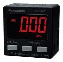


DP-001-P
DIGITAL PRESSURE SENSOR, 100KPA, M5
- Manufacturer: PANASONIC
- Product type: Pressure Transducers
- Port Style: M5
- Sensor Output: PNP Open Collector
- Supply Current: 30mA
- Voltage Rating: 24VDC
- Operating Pressure Max: 100kPa
- Pressure Measurement Type: Gauge
| Delivery and price | |
|---|---|
| Units per pack | 50 |
| Price | 51.34 € |
| Current stock | 10+ |
| Lead time | 30 days |
> For gas a

Conforming to | EMC Directive «

## **Simpler and Easier to Use**

2015.06[panasonic.net/id/pidsx/global]

## **Simple & Easy Operation**

**==> picture [480 x 266] intentionally omitted <==**

**----- Start of picture text -----**<br>
Pressure unit<br>setting mode<br>Two levels of setting mode for<br>Operation<br>easy operation of essential  RUN mode setting mode<br>functions<br>NO / NC<br>The “RUN mode” is for threshold value setting, zero point  setting mode<br>adjustment and key lock setting / release setting, and the  a1<br>“detailed setting mode” allows for basic settings for sensor  Response time<br>operation. The two-level setting mode configuration enables  • Threshold value setting setting mode<br>• Zero point adjustment<br>easy and immediate use of the product.<br>• Key lock setting / release Display color<br>setting mode<br>Settings<br>initializing mode<br>ZN =<br>Main menu for detailed setting mode<br>Operation setting mode* NO / NC setting mode Response time setting mode Display color setting mode<br>Select from EASY mode,  Set the comparative output  Select the response time from  Select the comparative output ON /<br>hysteresis mode or window  operation to NO or NC. 2.5 ms, 25 ms or 250 ms. OFF display color and the normal<br>comparator mode. display color from red or white.<br>**----- End of picture text -----**<br>


## **Two levels of setting mode for easy operation of essential functions**

The “RUN mode” is for threshold value setting, zero point adjustment and key lock setting / release setting, and the “detailed setting mode” allows for basic settings for sensor operation. The two-level setting mode configuration enables easy and immediate use of the product.

## **Main menu for detailed setting mode**

* For details of operation setting mode, see page 4.

## Functional Design

> Crisp on clicking feel . taeork

## **Black body for enhanced visibility of LCD display**

The unit body is completely black to make the LCD display easier to see.

## **Firm and crisp clicking feel**

The buttons offer firm and crisp clicking feel for smooth and reliable setting operations.

2

DP-0

Redesigned for improvement of pressure sensor usability from ground up

Simple Easy Setting

## - High Quality LCD Display

Pressure / setting display ~~es~~ **Simple and highly** Comparative output ON / OFF mark **visible display** The LCD offers a wide viewing angle Key lock mark OVER mark ~~=~~ (Moo so the display is easy to see even from

The LCD offers a wide viewing angle so the display is easy to see even from an oblique angle. The alphanumeric display (12-segment display), key lock mark and OVER mark further enhance the recognition of display.

Pressure unit display Low pressure type: kPa, kgf/cm[2] , bar, psi, mmHg High pressure type: MPa, kgf/cm[2] , bar, psi

RUN mode Detailed setting mode

## **Selection of display color from red or white**

The display color can be selected from red or white in accordance with the output operation. Since the detailed setting mode display is pink (unchangeable), the pressure sensor status can be easily recognized by color.

**==> picture [230 x 56] intentionally omitted <==**

**----- Start of picture text -----**<br>
Display color setting Mode Comparative output ONRUN modeComparative output OFF Detailed setting mode<br>Red for ON, white for OFF Red White<br>White for ON, red for OFF White Red<br>Pink<br>Red in normal status Red<br>White in normal status White<br>**----- End of picture text -----**<br>


## Compact & Light Weight Design

## **Extra-short depth and light weight**

The unit body measures only 24.9 mm 0.980 in in depth to allow installation in a narrow space. The main unit weighs only about 25 g. The lightweight unit means minimal load when mounted on a moving part such as a robot arm.

Comparison with Depth dimension[:] **[A][pp][rox. ][41][% shorter!]** previous model ( **DP-100** series standard Main unit pressure port type) weight : **Approx. 38% lighter!**

**==> picture [229 x 131] intentionally omitted <==**

**----- Start of picture text -----**<br>
Previous model<br>DP-0  series<br>— ( DP-100  series standard pressure port type)<br> Approx.<br>25 g < Actual size >  Approx . 40 g<br>24.9 mm<br>0.980 in 42.5 mm 1.673 in<br>**----- End of picture text -----**<br>


3

DP-0

High pressure type

**==> picture [75 x 9] intentionally omitted <==**

**----- Start of picture text -----**<br>
Low pressure type<br>**----- End of picture text -----**<br>


## Low Pressure Type and High Pressure Type Available

## **Two types to choose from according to applications**

**==> picture [483 x 153] intentionally omitted <==**

**----- Start of picture text -----**<br>
according to applications Pe Applications<br>The low pressure type can be used with positive or negative  Suction confirmation for  Reference pressure check<br>pressure, while the high pressure type is suitable for positive  electronic parts<br>pressure of up to 1 MPa.<br><Low pressure type><br>Ideal for applications such a —_<br>as suction. No<br>misoperations due to  <High pressure type><br>vacuum breakdown occur. Ideal for applications such<br>as checking reference<br>−100 kPa 0 kPa 100 kPa pressure. Can also be<br>used for simple suction.<br>Low<br>DP-001□<br>pressure type 1 MPa ke “ws<br>High DP-002□<br>pressure type _<br>**----- End of picture text -----**<br>


## Three Output Modes

## **Equipped with three output modes for use in a wide range of applications**

**==> picture [317 x 104] intentionally omitted <==**

**----- Start of picture text -----**<br>
(1) EASY mode (2) Hysteresis mode<br>This mode is used for comparative output ON /  This mode is used for setting comparative output<br>OFF control. hysteresis to the desired level and for carrying<br>out ON / OFF control.<br>H (Hysteresis)<br>P-1 ZN _A P-2<br>H (Hysteresis)<br>P-1<br>|i 0 | ees 0 LNA<br>Comparative  ON Comparative  ON<br>output OFF output OFF<br>H: 4 digits (fixed) (10 digits or more when using psi unit)  H: 2 digits or more (5 digits or more when using psi unit)<br>Pressure Pressure<br>**----- End of picture text -----**<br>


This mode is used for comparative output ON / OFF control.

**==> picture [156 x 103] intentionally omitted <==**

**----- Start of picture text -----**<br>
(3) Window comparator mode<br>This mode is used for setting comparative output<br>ON and OFF at pressures within the setting<br>range.<br>H (Hysteresis)<br>P-2<br>H (Hysteresis)<br>P-1<br>| 0 ZOES5LN~_aA<br>Comparative  ON<br>output OFF<br>H: 4 digits or more (10 digits or more when using psi unit)<br>Pressure<br>**----- End of picture text -----**<br>


4

DP-0

## Designed for Easy Installation

**==> picture [438 x 272] intentionally omitted <==**

**----- Start of picture text -----**<br>
Tight installation is<br>Panel mounting<br>bracket possible<br>An exclusive mounting bracket that is<br>suitable for 1 to 3 mm 0.039 to 0.118 in<br>panel thickness is available. SK SS am |<br>Panel mounting bracket<br>MS-DP1-8<br>),<br>Neat and 2 iN — J}<br>space a” | NZ<br>saving a  Ny oa |<br>me, ! =<br>Front protection cover |<br>| MS-DP1-3<br>| aa<br>“HY 23<br>. a |<br>[ce oop ioc = = = | ra .<br>A single<br>mounting hole<br>Tight installation is possible<br>**----- End of picture text -----**<br>


**==> picture [185 x 29] intentionally omitted <==**

**----- Start of picture text -----**<br>
Exclusive   Supports tight<br>installation<br>mounting bracket<br>**----- End of picture text -----**<br>


Space savings can also be achieved even when an L-shaped mounting bracket is used.

**==> picture [134 x 145] intentionally omitted <==**

**----- Start of picture text -----**<br>
Positioning bosses for easier<br>mounting bracket installation<br>Tight installation is possible<br>**----- End of picture text -----**<br>


## **MS-DP1-1**

**==> picture [186 x 185] intentionally omitted <==**

**----- Start of picture text -----**<br>
M3 (length 6 mm 0.236 in)<br>screws with washers<br>(Accessory for  MS-DP1-1 )<br>FI 6<br>Ceiling mounting Floor mounting<br>MS-DP1-5<br>M3 (length 6 mm 0.236 in)<br>screws with washers<br>(Accessory for  MS-DP1-5 )<br>&Cs<br>Rear mounting<br>**----- End of picture text -----**<br>


**Connection Cable can be connected cable with one-touch** ~~i~~ Connector attached cable (2 m 6.562 ft), as an accessory, can be connected easily with one-touch connection.

**Types without connector attached cable are also available DP-00□-J** Commercially-available connectors can be used for cable connections. Cables in required length can be used, so this contributes to reduction in waste of unwanted cables.

**==> picture [233 x 48] intentionally omitted <==**

**----- Start of picture text -----**<br>
Connection cable *<br>+s<br>* Options: 1 m 3.281 ft / 3 m 9.843 ft / 5 m 16.404 ft types are also available.<br>**----- End of picture text -----**<br>


**==> picture [118 x 25] intentionally omitted <==**

**----- Start of picture text -----**<br>
Commercially - available<br>parts can be used!<br>**----- End of picture text -----**<br>


Refer to p.6 for recommended commercially-available connectors.

5

DP-0 a **ORDER GUIDE**

**Model No.**

## **DP-00** LI **1 -** UO **P - J** Rated pressure range Cable ao PE

- **1** : −100.0 to +100.0 kPa (Low pressure type)

   - None : Connector attached cable 2 m 6.562 ft

- **2** : 0.000 to +1.000 MPa (High pressure type)

**J** : Type without connector attached cable

Comparative output

None : NPN output type

**P** : PNP output type

|Type<br>~~a~~|Appearance<br>~~a ~~|Rated pressure range<br>|Model No.<br>|Pressure port|Comparative output|
|---|---|---|---|---|---|
|Low pressure<br>type<br><br>~~LJ~~|***CN-14A-C2**<br>(Connector attached cable<br>2 m6.562 ft) is attached.<br> <br>sae<br>~~LJ~~|−100.0 to +100.0 kPa<br> ~~Pf~~<br>~~|~~<br>~~LJ~~|**DP-001**<br>~~f~~<br>~~|~~<br>~~LJ~~|M5 female thread<br>~~LJ~~|NPN open-collector transistor|
||||**DP-001-P**<br>~~f~~<br>~~|~~<br>~~LJ~~||PNP open-collector transistor|
|High pressure<br>type<br><br>~~LJ~~||0.000 to +1.000 MPa<br> ~~Pf~~<br>~~|~~<br>~~LJ~~<br>~~|~~|**DP-002**<br>~~f~~<br>~~|~~<br>~~LJ~~<br>~~|~~||NPN open-collector transistor|
||||**DP-002-P**<br>~~LJ~~<br>~~|~~||PNP open-collector transistor|


- (e.g.) Type without connector attached cable of **DP-001-P** is “ **DP-001-P-J** ”

**==> picture [55 x 10] intentionally omitted <==**

**----- Start of picture text -----**<br>
OPTIONS<br>**----- End of picture text -----**<br>


|Designation|Model No.<br>~~|~~|Description<br>~~|~~|Description<br>~~|~~|
|---|---|---|---|
|Connector<br>attached cable|**CN-14A-C1**<br>~~a~~<br>~~ee~~|Length: 1 m3.281 ft<br>~~a~~<br>~~ee~~|0.2 mm<br>24-core cabtyre cable with<br>connector on one end<br>Cable outer diameter:  ø3.7 mm<br>ø0.146 in|
||**CN-14A-C2**(Note)<br>~~a~~<br>~~ee~~<br>~~es ee~~|Length: 2 m6.562 ft<br>~~a~~<br>~~ee~~<br>~~ee~~||
||**CN-14A-C3**<br>~~ee ~~<br>~~es ee~~|Length: 3 m9.843 ft<br> ~~ee~~<br>~~ee~~||
||**CN-14A-C5**<br>~~es ee~~<br>~~a~~<br>~~a~~|Length: 5 m16.404 ft<br>~~ee~~<br>~~a~~<br>~~ee~~||
|Connector<br>attached cable<br>(Flexible cable)|**CN-14A-R-C1**<br>~~a~~<br>~~a~~<br>~~a~~<br>~~ee~~|Length: 1 m3.281 ft<br>~~a~~<br>~~a~~<br>~~ee~~<br>~~eee~~<br>|0.2 mm<br>24-core flexible cabtyre<br>cable  with connector on one end<br>Cable outer diameter:  ø3.7 mm<br>ø0.146 in|
||**CN-14A-R-C2**<br>~~a~~<br>~~a~~<br>~~ee~~<br>~~es~~|Length: 2 m6.562 ft<br>~~a~~<br>~~ee~~<br>~~eee~~<br>~~eee~~<br>||
||**CN-14A-R-C3**<br>~~a~~<br>~~ee~~<br>~~es eee~~<br>~~|~~|Length: 3 m9.843 ft<br>~~ee~~<br>~~eee~~<br>~~eee~~<br>~~eee~~||
||**CN-14A-R-C5**<br>~~ee ~~<br>~~es eee~~<br>~~|~~|Length: 5 m16.404 ft<br>~~eee~~<br> ~~eee~~<br>~~eee~~||
|Connector|**CN-14A**<br> <br>~~es eee~~<br>~~|~~|Set of 10 housings and 40 contacts<br> ~~eee~~<br>~~eee~~||
|Sensor mounting<br>bracket|**MS-DP1-1**<br>~~eee~~<br>~~||~~|Allows sensors to be installed on the flooring or ceiling.<br>Multiple sensors can also be mounted closely.<br>~~eee~~||
||**MS-DP1-5**<br>~~|~~<br>~~oe~~|Allows sensors to be installed on the wall.  Multiple sensors<br>can also be mounted closely.||
|Panel mounting<br>bracket|**MS-DP1-8**<br>~~|~~|Allows installation to panels with thickness of 1 to 3 mm0.039<br>to 0.118 in. Multiple sensors can also be mounted closely.||
|Front protection<br>cover|**MS-DP1-3**<br>~~|~~<br>~~oe~~|Protects the adjustment surfaces of sensors.<br>(Can be attached when using the panel mounting bracket)||


## **Recommended connector**

Contact: SPHD-001T-P0.5, Housing: PAP-04V-S (Manufactured by J.S.T. Mfg. Co., Ltd.) Note: Contact the manufacturer for details of the recommended products.

## **Recommended crimping tool**

Model No.: YC-610R (Manufactured by J.S.T. Mfg. Co., Ltd.) Note: Contact the manufacturer for details of the recommended products.

Note: The connector attached cable **CN-14A-C2** is supplied with the **DP-0** series.

6

DP-0

## **SPECIFICATIONS**

**==> picture [504 x 606] intentionally omitted <==**

**----- Start of picture text -----**<br>
Type Low pressure High pressure<br>NPN output DP-001 DP-002<br>Item PNP output DP-001-P DP-002-P<br>Type of pressure Gauge pressure<br>Rated pressure range −100.0 to +100.0 kPa   0.000 to +1.000 MPa<br>−101.0 to +101.0 kPa<br>2 −0.010 to +1.010 MPa<br>−1.030 to +1.030 kgf/cm 2<br>Set pressure range −1.010 to + 1.010 bar −0.1 to +10.30 kgf/cm−0.1 to + 10.10 bar<br>−14.65 to +14.65 psi<br>−0.1 to +146.5 psi<br>−756 to +756 mmHg<br>Pressure withstandability 500 kPa 1.5 MPa<br>Applicable fluid Air, non-corrosive gas<br>Selectable unit Low pressure type: kPa, kgf/cm2, bar, psi, mmHg    High pressure type: MPa, kgf/cm2, bar, psi<br>Supply voltage 12 to 24 V DC ±10 % Ripple P-P 10 % or less<br>Power consumption 30 mA or less<br><NPN output type> <PNP output type><br>NPN open-collector transistor PNP open-collector transistor<br>• Maximum sink current: 50 mA • Maximum source current: 50 mA<br>Comparative output<br>• Applied voltage:  30 V DC or less   • Applied voltage:  30 V DC or less<br>(between comparative output and 0 V) (between comparative output and +V)<br>• Residual voltage: 2 V or less (at 50 mA sink current) • Residual voltage: 2 V or less (at 50 mA source current)<br>Output operation Selectable either NO or NC by key operation<br>Hysteresis Minimum 2 digits (variable)<br>Repeatability ±0.2 % F.S. (within ±4 digits) ±0.4 % F.S. (within ±4 digits)<br>Response time 2.5 ms, 25 ms, 250 ms, selectable by key operation<br>Short-circuit protection Incorporated<br>Display 3 + 1/2 digits, 3-color (white / red / pink) LCD display (Display update period: 250 ms)<br>−101.0 to +101.0 kPa<br>2 −0.010 to +1.010 MPa<br>−1.030 to +1.030 kgf/cm 2<br>Displayable  −1.010 to + 1.010 bar −0.1 to +10.30 kgf/cm<br>pressure range −14.65 to +14.65 psi −0.1 to + 10.10 bar<br>−0.1 to +146.5 psi<br>−756 to +756 mmHg<br>Protection IP40 (IEC)<br>Ambient temperature 0 to +50 °C +32 to +122 °F (No dew condensation allowed), Storage: -10 to +60 °C +14 to +140 °F<br>Ambient humidity 35 to 85 % RH, Storage: 35 to 85 % RH<br>Voltage withstandability 500 V AC for one min. between all supply terminals connected together and enclosure<br>Insulation resistance 50 MΩ or more with 500 V DC megger between all supply terminals connected together and enclosure<br>Vibration resistance 10 to 150 Hz frequency, amplitude 0.75 mm 0.030 in or maximum acceleration 49 m/s2, in X, Y and Z directions for two hours each<br>Shock resistance 100 m/s2 acceleration (10 G approx.) in X, Y and Z directions for three times each<br>Pollution degree 2<br>Overvoltage category I<br>Usable altitude 2,000 m 6,562 ft or less<br>Temperature characteristics +10 to +40°C +50 to +104°F: Within ±1 % F.S. +10 to +40°C +50 to +104°F: Within ±2 % F.S.<br>(+20°C standard) 0 to +50°C 32 to +122°F: Within ±2.5 % F.S. 0 to +50°C 32 to +122°F: Within ±5 % F.S.<br>Grounding method Floating<br>Pressure port M5 female thread<br>Material Enclosure: PBT (glass fiber reinforced), LCD display: Acrylic, Pressure port: Brass (nickel plated),<br>Mounting threaded part: Brass, O-ring: Nitrile rubber (NBR), Key section: Polycarbonate<br>Weight 25 g approx.<br>Accessory CN-14A-C2  (Connector attached cable 2 m 6.562 ft): 1 pc.<br>Model No.<br>Environmental resistance<br>**----- End of picture text -----**<br>


Note: Where measurement conditions have not been specified precisely, the conditions used were an ambient temperature of +20 °C +68 °F.

7

DP-0

**I/O CIRCUIT AND WIRING DIAGRAMS**

## **NPN output type**

## **I/O circuit diagram**

**==> picture [239 x 126] intentionally omitted <==**

**----- Start of picture text -----**<br>
Terminal No.<br>Color code of connector attached cable<br>1 (Brown) +V<br>D1<br>3 (White) Not connected (Note) Load<br>+ 12 to 24 V DC<br>Tr D2 2 (Black) Comparative output − ±10 %<br>50 mA MAX.<br>ZD<br>4 (Blue) 0 V<br>Internal circuit Users’ circuit<br>Note: Open or, connect to 0 V.<br>Sensor circuit<br>**----- End of picture text -----**<br>


Symbols…D1, D2: Reverse supply polarity protection diode ZD: Surge absorption zener diode Tr: NPN output transistor

## **Terminal arrangement diagram**

**==> picture [68 x 46] intentionally omitted <==**

**==> picture [240 x 109] intentionally omitted <==**

**----- Start of picture text -----**<br>
1 2 3 4<br>Terminal<br>Designation<br>No.<br>+V<br>Comparative output<br>Not connected (Note)<br>0V<br>**----- End of picture text -----**<br>


**==> picture [94 x 8] intentionally omitted <==**

**----- Start of picture text -----**<br>
Note: Open or, connect to 0 V.<br>**----- End of picture text -----**<br>


## **PNP output type**

## **I/O circuit diagram**

**==> picture [239 x 111] intentionally omitted <==**

**----- Start of picture text -----**<br>
Terminal No.<br>Color code of connector attached cable<br>1 (Brown) +V<br>D1<br>ZD<br>50 mA MAX.<br>Tr D2 2 (Black) Comparative output +− 12 to 24 V DC±10 %<br>3 (White) Not connected (Note) Load<br>4 (Blue) 0 V<br>Internal circuit Users’ circuit<br>Sensor circuit<br>**----- End of picture text -----**<br>


Note: Open or, connect to 0 V.

Symbols…D1, D2: Reverse supply polarity protection diode ZD: Surge absorption zener diode Tr: PNP output transistor

## **Terminal arrangement diagram**

**==> picture [240 x 129] intentionally omitted <==**

**----- Start of picture text -----**<br>
1 2 3 4<br>Terminal<br>Designation<br>No.<br>+V<br>Comparative output<br>Not connected (Note)<br>0V<br>**----- End of picture text -----**<br>


Note: Open or, connect to 0 V.

8

DP-0

## **PRECAUTIONS FOR PROPER USE**

- Never use this product as a sensing device for personnel protection.

- In case of using sensing devices for personnel protection, use products which meet laws and standards, such as OSHA, ANSI or IEC etc., for personnel protection applicable in each region or country.

- This product is used for noncorrosive gas. The product shall not be used for liquid or corrosive gas. Never use fluids having inflammability, toxicity, etc., that affect the human body, either.

## **Part description**

**==> picture [231 x 90] intentionally omitted <==**

**----- Start of picture text -----**<br>
Digital display unit<br>ON mark<br>OFF mark Connecting<br>connector<br>Key lock mark<br>OVER mark<br>Mode  Pressure port<br>selection key (M5 female thread)<br>Setting value UP key<br>Setting value DOWN key<br>**----- End of picture text -----**<br>


## **Piping**

- •When using this product, connect a joint available in the market to the pressure port. At the time, the tightening torque should be 1.0 N·m or less.

## **Mounting**

- •Use sensor mounting bracket **MS-DP1-1** prepared independently. When mounting this product with sensor mounting bracket, etc., the tightening torque should be 0.5 N·m or less.

**==> picture [177 x 91] intentionally omitted <==**

**----- Start of picture text -----**<br>
M3 (length 6 mm 0.236 in)<br>screws with washers<br>(Accessory with  MS-DP1-1 )<br>Sensor mounting<br>bracket  MS-DP1-1<br>(Optional)<br>**----- End of picture text -----**<br>


- •Panel fittings **MS-DP1-8** (optional) and front cover **MS-DP1-3** (optional) are available.

- •For the method for mounting panel fittings, refer to the instruction manual that came with the **MS-DP1-8** .

## **Wiring**

- •Make sure that the power supply is OFF while performing the wiring operation.

- •Verify that the supply voltage variation is within the rating.

- •If power is supplied from a commercial switching regulator, ensure that the frame ground (F.G.) terminal of the power supply is connected to an actual ground.

- •In case noise generating equipment (switching regulator, inverter motor, etc.) is used in the vicinity of this product, connect the frame ground (F.G.) terminal of the equipment to an actual ground.

- •When extending the cable, use a cable whose conductor crosssectional area is 0.3 mm2 or more. The cable can be extended to up to 10 m 32.808 ft in total length.

- •Do not run the wires together with high-voltage lines or power lines or put them in the same raceway. This can cause malfunction due to induction.

- •Do not apply stress directly to the connection cable leader or to the connector.

## **Connection**

## **How to connect**

- Release lever

- •Insert the cable with connector **CN-14A** ( **-R** ) **-C□** into this product’s connection connector section as shown in the right figure.

- **How to disconnect** •Pressing the release lever of the cable Cable with connector

- with connector, pull out the connector. **CN-14A** ( **-R** ) **-C□**

Note: Do not pull by holding the cable without pressing the release lever, as this can cause cable break or connector break.

## **Factory setting**

**==> picture [240 x 101] intentionally omitted <==**

**----- Start of picture text -----**<br>
Type Low pressure type High pressure type<br>Operation setting EASY mode<br>NO / NC setting NC NO<br>Threshold value −50.0 0.500<br>Pressure unit kPa MPa<br>Display color Red when ON, White when OFF<br>Response speed 2.5 ms<br>**----- End of picture text -----**<br>


## **Error indication**

**==> picture [240 x 162] intentionally omitted <==**

**----- Start of picture text -----**<br>
Error indication Description Remedy<br>The load is short-circuited<br>Turn OFF the power and<br>causing an overcurrent to flow. check the load.<br>Applied pressure at the<br>pressure port should be<br>Pressure is applied during  brought to atmospheric<br>zero point adjustment. pressure and zero-point<br>adjustment should be done<br>again.<br>The applied pressure<br>exceeds the upper limit of<br>the displayed pressure<br>range. Applied pressure range<br>should be brought within<br>The applied pressure<br>the rated pressure range.<br>exceeds the lower limit<br>(back pressure) of the<br>displayed pressure range.<br>**----- End of picture text -----**<br>


When other error massage is displayed, contact us.

## **Others**

- •This product has been developed / produced for industrial use only.

- •The product shall be used only within the rated pressure range.

- •Do not apply pressure exceeding the pressure resistance. Otherwise, destruction of diaphragm occurs, preventing the product to perform normal operation.

- •Do not use during the initial transient time (0.5 sec.) after the power supply is switched ON.

- •The specification may not be satisfied in a strong magnetic field.

- •This product is suitable for indoor use only.

- •Take care that strong impact such as fall is not given to this product. Otherwise, it may be destroyed.

- •Avoid dust, dirt, and steam.

- •Take care that the product does not come into contact with organic solvents such as thinner.

- •Take care that the product does not come into contact with oil or grease.

- •Take care that the product does not come into contact with strong acid or alkaline.

- •Do not insert wire into the pressure port. Otherwise, destruction of diaphragm occurs, preventing the product to perform normal operation.

9

DP-0

**DIMENSIONS (Unit: mm in)**

The CAD data can be downloaded from the website.

**==> picture [482 x 149] intentionally omitted <==**

**----- Start of picture text -----**<br>
Sensor<br>24.9 0.980<br>Connector<br>30 1.181 20 0.787 4.9 0.193 20 0.787<br>Display<br>30 ø8.35 20 2-ø2.5 0.098, 5 0.197 deep<br>1.181 ø0.329 0.787<br>Setting value DOWN key 1.3 0.051 M5 female thread, 4 0.157 deep<br>Mode selection key<br>Setting value UP key 2-M3 female thread, 4 0.157 deep<br>**----- End of picture text -----**<br>


## **DP-00□**

## **MS-DP1-1**

**Sensor mounting bracket (Optional)**

**==> picture [435 x 210] intentionally omitted <==**

**----- Start of picture text -----**<br>
ø2.3ø0.091 Assembly dimensions<br>22 2-R2.1 R0.083<br>9.5 0.866<br>0.57114.5 0.374 1<br>0.039<br>0.1654.2 21 2-R2.1 R0.083 0.3749.5 0.57114.5<br>0.827 4.2<br>0.165 20<br>30 0.787<br>1.181<br>20 2-ø3.5 ø0.138<br>0.787 24.9<br>13 0.98<br>0.512<br>4.9 0.193<br>20 R13 5.3 45 ø8.35 ø0.329<br>0.787 R0.512 (         )0.209 (         )1.772<br>30<br>t 0.079t 2 0.78720 0.2175.5 1.73244 1.1811.77245 t 2 1.18130<br>15 1.3 t 0.079<br>0.591 0.051<br>Material:  Cold rolled carbon steel (SPCC) 30 1.181<br>(Uni-chrome plated)<br>Two M3 (length 6 mm 0.236 in) screws with washers are attached.<br>**----- End of picture text -----**<br>


**==> picture [38 x 56] intentionally omitted <==**

## **MS-DP1-5**

## **Sensor mounting bracket (Optional)**

**==> picture [163 x 174] intentionally omitted <==**

**----- Start of picture text -----**<br>
22.75<br>0.896<br>29.5<br>1.161<br>20 ø4.5 28<br>4.5 0.787 ø0.177 1.102<br>0.177<br>8.5 0.335<br>44.5<br>30 1.752<br>20 1.181<br>0.787<br>t 1.5<br>13.5 2-ø3.5 ø0.138 t 0.059<br>0.531<br>20<br>0.787<br>**----- End of picture text -----**<br>


Material:  Stainless steel (SUS304) Two M3 (length 6 mm 0.236 in) screws with washers are attached.

## **Assembly dimensions**

**==> picture [243 x 216] intentionally omitted <==**

**----- Start of picture text -----**<br>
R6.75<br>R0.266<br>16<br>0.630<br>24.9<br>0.980<br>4.9<br>0.193<br>49.5 ø8.35 ø0.329<br>(         )1.949<br>49.5<br>1.949<br>20<br>0.787 28.5<br>1.122<br>ø4.5 1.3<br>ø0.177 0.051<br>20 4.5 26.5<br>0.787 0.177 1.043 t 1.5<br>29.5 48 t 0.059<br>1.161 1.890<br>30<br>1.181<br>**----- End of picture text -----**<br>


10

DP-0

**DIMENSIONS (Unit: mm in)**

The CAD data can be downloaded from the website.

## **MS-DP1-8  MS-DP1-3**

## **Mounting drawing with DP-00□**

## **Panel mounting bracket (Optional), Front protection cover (Optional)**

## **Panel cut-out dimensions**

**==> picture [83 x 6] intentionally omitted <==**

**----- Start of picture text -----**<br>
When 1 unit is installed<br>**----- End of picture text -----**<br>


**==> picture [62 x 33] intentionally omitted <==**

**==> picture [231 x 178] intentionally omitted <==**

**----- Start of picture text -----**<br>
11<br>(39.3 1.547) 0.433<br>34.5 1.358 Front protection  7.2 12.8 4.9 0.193<br>cover 0.283 0.504<br>ø8.35 ø0.329<br>1.35834.5 (       )0.78720 A<br>50 1.969 8.5<br>0.335<br>33.4 1.315 Panel thickness<br>dimension 1 to 3 mm<br>0.039 to 0.118 in<br>33.4 Connector<br>1.315<br>(52 2.047 max)<br>View A<br>**----- End of picture text -----**<br>


**==> picture [228 x 74] intentionally omitted <==**

**----- Start of picture text -----**<br>
31−0.40<br>1.220 −0.0160<br>31−0.40 1.220 −0.0160<br>When “n” units are installed  When “n” units are installed<br>horizontally in series vertically in series<br>**----- End of picture text -----**<br>


**==> picture [244 x 119] intentionally omitted <==**

**----- Start of picture text -----**<br>
31 1.220 × n + 3.5 0.138 × (n-1) 31−0.40<br>0 1.220 −0.0160<br>31−0.4<br>0<br>1.220 −0.016<br>55 2.165<br>or more<br>31 1.220 × n +<br>3.5 0.138 × (n-1)<br>55 2.165<br>or more<br>Note: The panel thickness should be  Note: The panel thickness should be<br>1 to 3 mm 0.039 to 0.118 in. 1 to 3 mm 0.039 to 0.118 in.<br>**----- End of picture text -----**<br>


Material: Polyacetal (Panel mounting bracket) Polycarbonate (Front protection cover)

## **CN-14A** (- **R** ) **-C□**

**Connector attached cable (Optional, CN-14A-C2 is attached to the sensor)**

**==> picture [225 x 82] intentionally omitted <==**

**----- Start of picture text -----**<br>
L<br>35 50<br>(         )1.378 (         )1.969<br>8 8<br>(         )0.315 (         )0.315<br>ø3.7 ø0.146 cable<br>**----- End of picture text -----**<br>


**==> picture [163 x 72] intentionally omitted <==**

**----- Start of picture text -----**<br>
Model No. Cable length L (mm in)<br>CN-14A ( -R ) -C1 1,000 39.370<br>CN-14A ( -R ) -C2 2,000 78.740<br>CN-14A ( -R ) -C3 3,000 118.110<br>CN-14A ( -R ) -C5 5,000 196.850<br>**----- End of picture text -----**<br>


11

~~Lo~~ **Pressure Sensor Lineup**

## **Higher precision, more advanced function Dual Display Digital Pressure Sensor** For gas **- DP 100 SERIES Ver.2** ~~ee~~

**==> picture [242 x 51] intentionally omitted <==**

**----- Start of picture text -----**<br>
Conforming to Ce Ws Certification of Certification ©  •Dual-screen 3-color display (red, green, orange) for added<br>EMC Directive Recognition  [ DP-101  ( A ) /  102  ( A ) only] ease of operation.<br> • Wide variation of pressure ports.<br> •Provided with 2 outputs<br>(standard type).<br>**----- End of picture text -----**<br>


   - •Provided with analog output or external input (multi-function type).

   - •Provided with copy function for reduced man-hours and human error.

   - •Oil-free type also available for prevention of entry of oil or grease in air pipes.

   - •Compound pressure types (for low pressure / for high pressure) are available.

- **Installation on a panel or moving part possible Head-separated Dual Display Digital Pressure Sensor** For gas **- -**

- **DPC 100 SERIES DPH 100 SERIES**

- ~~el~~ Conforming to C€ ALi Certification of •High response speed of 500 μs. EMC Directive Recognition •Automatic recognition of sensor head without initial setting.

- •Sensor head can be installed easily using an Allen wrench.

- •Standalone use of sensor head is possible.

   - •Provided with 2 outputs (analog voltage and current).

   - •Compound pressure type, positive pressure type and negative pressure type are available.

## **Detection of liquid pressure Head-separated Dual display Digital Pressure Sensor** For gas & liquid **- - DPC L100 SERIES DPH L100 SERIES**

- Conforming to CE •High-precision liquid / air pressure detection and EMC Directive excellent operability. •Compact stainless steel body withstands pressure of up to 50 MPa.

   - •Oil-less, single diaphragm structure.

   - •Mounted with throttle to achieve high resistance to pressure surge.

   - •Standalone use of sensor head is possible.

   - •Provided with 2 outputs (analog voltage and current).

   - •Compound pressure type and positive pressure type are available.

**Multi-unit connection and network communication supported Head-separated Dual Display Digital Pressure Sensor** For gas

## **- - DPS 400 SERIES DPH 100 SERIES**

- Conforming to CE •Ultra-high response speed of 150 μs. EMC Directive •Network communication is possible.

- •Allows connection of up to 16 units and copying of settings.

   - •One-touch cable for reduced wiring work.

   - •Sensor head can be installed easily using an Allen wrench.

   - •Standalone use of sensor head is possible.

   - •Provided with 2 outputs

   - •Compound pressure type, positive pressure type and negative pressure type are available.

## **Disclaimer**

The applications described in the catalog are all intended for examples only. The purchase of our products described in the catalog shall not be regarded as granting of a license to use our products in the described applications. We do NOT warrant that we have obtained some intellectual properties, such as patent rights, with respect to such applications, or that the described applications may not infringe any intellectual property rights, such as patent rights, of a third party.

Please contact:

2431-1 Ushiyama-cho, Kasugai-shi, Aichi, 486-0901, Japan Global Sales Department

■ Telephone: +81-568-33-7861 ■ Facsimile: +81-568-33-8591 panasonic.net/id/pidsx/global

All Rights Reserved ©                                                                         2015

No. CE-DP0-10 June, 2015

Specifications are subject to change without notice.

Printed in Japan
Updated at February 9, 2023
Panasonic Industry is a global leader in the design and manufacture of high-quality electronic components. Renowned for a commitment to continuous innovation, the company provides the essential building blocks that empower modern engineering. From industrial automation to consumer electronics, Panasonic's components are trusted worldwide for their outstanding reliability, efficiency, and long-term performance. The extensive portfolio is anchored by a massive selection of passive components, featuring an industry-leading range of aluminium electrolytic, film, and polymer capacitors. Alongside these advanced capacitance solutions, engineers rely on Panasonic's robust power inductors and a highly versatile array of electromechanical devices, including solid-state, power, and signal relays engineered to excel in demanding environments. Beyond core passives and switching solutions, the offering encompasses critical circuit protection devices such as TVS varistors and NTC thermistors, as well as sophisticated thermal management materials. Panasonic also delivers precision light and motion sensors, highly reliable batteries, and advanced Bluetooth and WLAN connectivity modules, providing a comprehensive ecosystem of components to support next-generation technological design.
About Novapart
Novapart is a B2B electronic component broker specialising in stock shortages and cost reduction. We source hard-to-find parts and identify compliant alternatives across a catalogue of 410,000+ components from 500+ manufacturers.
Learn more →Stock Shortage Specialist
When a component is unavailable, discontinued or has an unacceptable lead time, we tap into our network of vetted European and Asian distributors to source what you need — without compromising on quality or traceability.
Request a quote →Compliant Alternatives
We identify pin-to-pin, electrically equivalent substitutes that meet the same certifications (RoHS, AEC-Q100, REACH) as your original specification — validated against datasheets, not just part numbers. Often at a lower cost.
BOM Analysis service →