
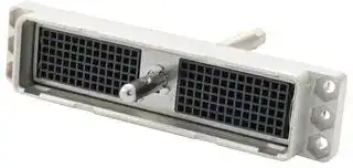


DLM1-156P
Connector, ZIF, DLM, 156 Contacts, 2.54 mm, Plug, 6 Rows
- Manufacturer: ITT CANNON
- Product type:
- Product Range:DLM Series; No. of Contacts:156Contacts; Card Edge / Backplane Connector Type:Backplane; Pitch Spacing:2.54mm; Gender:Plug; Contact Termination Type:-; No. of Rows:6Row
- Gender: Plug
- Row Pitch: 2.54mm
- No. of Rows: 6Rows
- Pitch Spacing: 2.54mm
- Product Range: DLM
- Contact Plating: -
- No. of Contacts: 156Contacts
- Contact Material: -
- Contact Termination Type: -
- Card Edge / Backplane Connector Type: Backplane
| Delivery and price | |
|---|---|
| Units per pack | 25 |
| Price | 187.86 € |
| Current stock | 50+ |
| Lead time | 30 days |
## **ITT Cannon DL** Series ZIF Connectors

## **HIGH-DENSITY ZIF CONNECTORS**

ITT Cannon DL series connectors are versatile, high-density ZIF connectors (zeroinsertion force) with 60 contact, 96 contact and 156 contact versions. DL series ZIF connectors are excellent medical connectors and are suited for other applications requiring no sliding force during mating and unmating, such as sound, lighting and entertainment equipment. The new ITT Cannon DLM shielded metal connector offers a stronger, light-weight aluminum housing that is nickel-plated for maximum shielding. For more details on the ITT Cannon DL series of zero-insertion force (ZIF) connectors, please see the product specifications below.

## APPLICATIONS

## **MEDICAL**

Ultrasound diagnostic Patient monitoring Hospital equipment

## **TEST & INSTRUMENTATION**

Avionics Automated test equipment Computer & peripheral equipment Semiconductor

## **ENTERTAINMENT**

Recording studio equipment Stage lighting & sound Broadcasting equipment

## **TELECOMMUNICATION**

Systems interconnect Manufacturing test equipment Switching systems

## **TRANSPORTATION**

## FEATURES

## **COMMERCIAL/INDUSTRIAL MANUFACTURING**

Automation Robotics Electrical controls

## **TRUE ZERO INSERTION FORCE (ZIF)**

## **CONNECTORS**

There is no build up of mating force typically associated with high pin count style connectors, so mating and un-mating is as easy as twisting a handle.

Locomotive systems Automotive electronics Aircraft simulators

## **WIDE SELECTION OF TERMINATIONS**

Crimp, printed circuit, square post and solder buss style contacts give you maximum flexibility to wire your connectors.

## **NEW NICKEL-PLATED ALUMINUM HOUSINGS**

## **LONG MATING LIFE**

10,000 matings minimum allows these connectors to be used in testing and burn-in applications.

## **HIGH PIN COUNT**

60, 96, 156, 260, 360, 624, 1248 and even 2496 contacts make the DL series one of the highest pin count per connector series available.

The DLM1/2/3 (60, 96 & 156 pin) versions are now available in a strong metal shell, fully EMI/RFI-shielded version that can mate with the standard plastic housing version. This allows for easy upgrade to a shielded version without sacrificing intermatability of units already in the field.

## **CONTACT WIPING**

During mating, the contacts wipe lightly together, which helps clean the contact mating area and assures low contact resistance needed for digital or low current applications.

For assistance in Europe and China, please see the back cover for a complete listing of our branch offices and contact numbers. Specifications subject to change.

**309**

TECH SPECS

## **MATERIALS & FINISHES**

DL1/2/3 Glass-filled thermoplastic, UL94V1-rated, Color: black DL4 Aluminum alloy, cadmium-plated housing, clear anodized mounting plate Shells DL5 Glass-filled thermoplastic, UL94V0-rated, Color: black DLM1/2/3/5/6 Aluminum alloy, nickel-plated Actuators & Plug Insert Retainers Stainless steel, passivated Contacts Copper alloy Crimp 50μ inches gold over 50μ inches nickel mating area gold flash on balance Crimp 20μ inches gold over 50μ inches nickel mating area tin lead on balance Plating Square Post 50μ inches gold over 50μ inches nickel mating area gold flash on balance Square Post 20μ inches gold over 50μ inches nickel mating area gold flash on balance PC/RC 20μ inches gold over 50μ inches nickel mating area tin lead on balance DL4 Glass-filled thermoplastic, UL94V1-rated, Color: grey Insulators DLM1/2/3/5/6 Glass-filled thermoplastic, UL94V0-rated, Color: black **ELECTRICAL DATA** 1200 Vac RMS – Crimp & square post contacts Dielectric Withstanding Voltage 1000 Vac RMS – PC/RC round PCB contacts 750 Vac RMS – DL4 5 Amps maximum – Crimp & square post contacts Current Rating 4 Amps maximum – PC/RC contact 10 Amps up to 60 Amps maximum for buss contacts

**==> picture [336 x 305] intentionally omitted <==**

**----- Start of picture text -----**<br>
DL1 DL2<br>7.0 7.0<br>DLM1 DLM2<br>gett! t {tt tt | Pe<br>5---s0neeen petl TTT<br>5 3.0 | OPERATING RANGELU T Lt = 3.0oreaincrance<br>a pl | cell<br>ee EL<br>10 20 30 40 SO 60 70 80 90 100 110 10 20 30 40 50<br>AMBIENT TEMPERATURE (t)°C. AMBIENT<br>DL3 DL3 TEMPERATURE/CURRENT RATING DL4 DL4<br>7.0<br>DLM3 e-[TTITTITI5 TTT<br>eabem!| | tllls foo tt tt<br>2 aa e777<br>= OOO Z to<br>aolorenarncnaneeym | | |<br>i imce 2 Bee<br>20SERRE UE is ee ae<br>LL mame | | Oy 5<br>10 20 30 40 70 80 100 110 10 » MBIENT<br>AMBIENT TEMPERATURE (t)°C.<br>Wire Range Sizes 32 AWG –18 AWG<br>15 milliohms maximum – Crimp & square post contacts<br>Contact Resistance 20 milliohms maximum – Crimp 32-30 AWG contacts<br>30 milliohms maximum – PC/RC contacts<br>Insulation Resistance 5000 megohms minimum<br>**----- End of picture text -----**<br>


**NOTE:** The Ambient Temperature Curves shown represent the rated current carrying capacity of the Cannon DL1/2/3/4 and DLM1/2/3 electrical connectors, derated to 80% of the value recorded using the methods specified by International Electro-Technical Commission Document 48 (1975).

Current was applied to the total connector (all contacts) in one-half ampere increments and maintained at each current level until thermal stability was achieved. A thermocouple inserted into the “hottest area” of each connector then measured the connector temperature at the same time that an ambient temperature reading was taken. The difference between the two measured values is the heat rise or self-heating created solely by the current flow; this temperature rise for the current level was deducted from the insulator material rated temperature. These values were then derated to 80% to obtain the curves shown.

For assistance in North America: +1 800.642.8750 for Pricing/Delivery or +1 800.523.0727 Tech Support  •  www.peigenesis.com • sales@peigenesis.com

**310**

TECH SPECS

## **MECHANICAL**

|**MECHANICAL**||
|---|---|
|OperatingTemperature|-55°C to105°C;DL4 -55°C to71°C|
|Durability|10,000 Mating cycles minimum DL/DLM<br>20,000Mating cyclesminimum DL4|
|Insulation Strip Length|32 to 22 AWG .130” (3.30mm)<br>20 to18AWG.160”(4.06mm)|
||30 to 28 AWG .053” (1.35mm) maximum|
|Insulation Diameter|26 to 24 AWG .065” (1.65mm) maximum|
||22to18AWG.074”(1.88mm)maximum|
|||
||AWG<br>Lbs.|
||32<br>1|
||30<br>1.5|
||28<br>3|
|Crimp Tensile Strength min. lbs.|26<br>10|
||24<br>15|
||22<br>15|
||20<br>19|
||18<br>30|
|||
|Chemical Resistance|Salt spray per MIL-STD-202 method101Condition B(48hours)|
|Vibration|Per MIL-STD-202 method 204 Condition C<br>Per MIL-STD-167-1/2 Modified (DL4)|
|Shock|Per MIL-STD-202 method213 Condition A(50g’s)|
|Contact Type|Crimp, wire wrap, printed circuit board, buss contacts - solder or crimp<br>lug tab|
|NumberofCircuits|60 to2496|
|ContactInsertion|Hand-insertablefrom rear,noinsertiontool required|
|ContactRetention|8lbs.(35.585newtons)minimum|
|Contact Spacing|.100"(25.4mm) square grid|
|Polarization|By centerand/orcornerpolarizing postkit|
|Approvals|UL94V1and UL94V0materials|


## **HOW DL/DLM HAND-ACTUATED CONNECTORS WORK**

For assistance in Europe and China, please see the back cover for a complete listing of our branch offices and contact numbers. Specifications subject to change.

**311**

HOW TO ORDER DL/DLM

## **PLUGS**

|NUMBER<br>OF<br>CONTACTS|PC TAIL .280" (7.11MM) SQUARE .025” (.64MM)|PC TAIL .280" (7.11MM) SQUARE .025” (.64MM)|PC TAIL .280" (7.11MM) SQUARE .025” (.64MM)|PC TAIL .280" (7.11MM) SQUARE .025” (.64MM)|PC TAIL ROUND .280"<br>(7.11MM)DIA. .020”(.50MM)|
|---|---|---|---|---|---|
||NON-SHIELDED<br>~~PO~~||SHIELDED|||
||50µ" GOLD<br>~~PO~~|20µ" GOLD<br>~~PO~~|50µ" GOLD|20µ" GOLD|20µ" GOLD|
|60|-<br>~~|~~|Contact us<br>~~fF~~|DLM3-60PW6A<br>112138-0000<br>~~fF~~|DLM3-60PW6<br>112138-0001<br>~~fF~~|DLM3-60PC<br>127050-0223|
|96<br>~~Mm~~|DL2-96PW6A<br>110777-0025<br>~~|~~<br>~~Mm~~<br>~~ee~~|Contact us<br>~~fF~~<br>~~Mm~~<br>~~|~~<br>|DLM2-96PW6A<br>112136-0000<br>~~fF~~<br>~~Mm~~<br>~~|~~<br>|DLM2-96PW6<br>112136-0001<br>~~fF~~<br>~~Mm~~<br>|DLM2-96PC<br>127050-0215|
|156<br>~~Mm~~|DL1-156PW6A<br>110535-0030<br>~~Mm~~<br>~~|~~<br>~~ee~~<br>~~|~~|DL1-156PW6<br>110535-0026<br>~~Mm~~<br>~~|~~<br>~~|~~<br>~~ee~~|DLM1-156PW6A<br>112134-0000<br>~~Mm~~<br>~~|~~<br>~~|~~<br>~~ee~~|DLM1-156PW6<br>112134-0001<br>~~Mm~~<br>~~|~~<br>~~ee~~|DLM1-156PC<br>127050-0207|
|260|DL5-260PW6A<br>111986-0000<br>~~ee~~<br>~~|~~|Contact us<br>~~|~~<br>~~ee~~|DLM5-260PW6A<br>112086-0000<br>~~|~~<br>~~ee~~|DLM5-260PW6<br>112086-0002<br>~~ee~~|DLM5-260PC<br>127050-0111|
|360|Contact us<br>~~ee ~~<br>~~|~~|Contact us<br>~~|~~<br> ~~ee~~<br>~~fF~~|DLM6-360PW6A<br>111995-0000<br>~~|~~<br>~~ee~~<br>~~fF~~|DLM6-360PW6<br>111995-0001<br>~~ee~~<br>~~fF~~|DLM6-360PC<br>127050-0097|
|624|DL4-624PW6A<br>110959-0042<br> <br>~~|~~|Contact us<br> ~~ee ~~<br>~~fF~~|-<br> ~~ee ~~<br>~~fF~~|-<br> ~~ee~~<br>~~fF~~|-|
|1248|Contact us|Contact us|-|-|-|
|2496|Contact us|Contact us|-|-|-|


## **RECEPTACLES**

|NUMBER<br>OF<br>CONTACTS|PC TAIL .280" (7.11MM) SQUARE .025” (.64MM)|PC TAIL .280" (7.11MM) SQUARE .025” (.64MM)|PC TAIL .280" (7.11MM) SQUARE .025” (.64MM)|PC TAIL .280" (7.11MM) SQUARE .025” (.64MM)|PC TAIL ROUND .280"<br>(7.11MM)DIA. .020”(.50MM)|
|---|---|---|---|---|---|
||NON-SHIELDED<br>~~pO~~||SHIELDED<br>~~pO~~|||
||50µ" GOLD<br>~~pO~~<br>~~ee~~|20µ" GOLD<br>~~pO~~<br>~~ee~~|50µ" GOLD<br>~~pO~~<br>~~eee~~|20µ" GOLD<br>~~eee~~|20µ" GOLD<br>~~eee~~|
|60|DL3-60RW6B<br>110901-0010<br>~~ee~~|Contact us<br>~~ee~~|DLM3-60RW6B<br>112139-0000<br>~~eee~~|-<br>~~eee~~|DLM3-60RC<br>127050-0227<br>~~eee~~|
|96|DL2-96RW6B<br>110855-0014<br>~~ee~~<br>~~|~~|Contact us<br>~~ee ~~<br>~~|~~<br>~~fT~~|DLM2-96RW6B<br>112137-0000<br> ~~eee~~<br>~~fT~~|-<br>~~eee~~<br>~~fT~~|DLM2-96RC<br>127050-0366<br>~~eee~~<br>~~fT~~|
|156|DL1-156RW6B<br>110536-1007|DL1-156RW6<br>110536-1009|DLM1-156RW6B<br>112135-0000|-|DLM1-156RC<br>127050-0211|
|260|DL5-260RW6B<br>111987-0000|Contact us|DLM5-260RW6B<br>112087-0000|-|DLM5-260RC<br>127050-0112|
|360|Contact us|Contact us|DLM6-360RW6B<br>111996-0001|-|DLM6-360RC<br>127050-0098|
|624<br>~~re~~|DL4-624RW6B<br>110960-0048<br>~~re~~|Contact us<br>~~re~~|-<br>~~re~~|-<br>~~re~~|-<br>~~re~~|
|1248|Contact us|Contact us|-|-|-|
|2496|Contact us|Contact us|-|-|-|


For assistance in North America: +1 800.642.8750 for Pricing/Delivery or +1 800.523.0727 Tech Support  •  www.peigenesis.com • sales@peigenesis.com

**312**

HOW TO ORDER DL/DLM

## **PLUGS**

**==> picture [527 x 305] intentionally omitted <==**

**----- Start of picture text -----**<br>
PC WIRE WRAP/PC TAIL .605” (15.37 MM)   PC WIRE WRAP/TAIL LENGTH .125"<br>FOR CRIMP AND INSERT CONTACTS<br>SQUARE .025” (.64MM) (3.18MM) SQUARE .025” (.64MM)<br>NON-SHIELDED<br>NUMBER<br>SHIELDED 50 NON SHIELDED 50  SHIELDED 50<br>OF  NON-SHIELDED SHIELDED<br>CONTACTS 50µ" GOLD 50µ” GOLD 50µ” GOLD<br>50µ" GOLD 20µ" GOLD<br>DL3-60PW4A  DL3-60PW4  DLM3-60PW4A  DLM3-60P w/.125  DL3-60P               DLM3-60P<br>60 Contact us<br>110900-0013 110900-0006 112138-0001 112138-0002 110900-0008 127050-0220<br>DL2-96PW4A  DL2-96PW4  DLM2-96PW4A  DLM2-96P w/.125  DL2-96P               DLM2-96P<br>96 Contact us<br>110777-0022 110777-0008 112136-0001 112136-0002 110777-0000 127050-0212<br>DL1-156PW4A  DL1-156PW4  DLM1-156PW4A  DL1-156P w/.125  DLM1-156P w/.125  DL1-156P               DLM1-156P<br>156<br>110535-0025 110535-0012 112134-0001 110535-0040 112134-0002 110535-0000 127050-0204<br>DL5-260PW4A  DLM5-260PW4A  DLM5-260P w/.125  DL5-260P                 DLM5-260P<br>260 Contact us Contact us<br>111986-0003 112086-0002 112086-0003 111986-0014 127050-0109<br>360 - Contact us DLM6-360PW4A  Contact us DLM6-360P w/.125  - DLM6-360P<br>111995-0001 111995-0007 127050-0034<br>624 DL4-624PW4A  DL4-624PW4  - Contact us - DL4-624P              -<br>110959-0035 110959-0011 110959-0002<br>1248 Contact us Contact us - Contact us - DL4-1248P             -<br>110959-0003<br>2496 Contact us Contact us - Contact us - DL4-2496P              -<br>110959-0004<br>**----- End of picture text -----**<br>


## **RECEPTACLES**

**==> picture [527 x 303] intentionally omitted <==**

**----- Start of picture text -----**<br>
PC WIRE WRAP/PC TAIL .605” (15.37 MM)   PC WIRE WRAP /TAIL LENGTH .125”<br>FOR CRIMP AND INSERT CONTACTS<br>SQUARE .025” (.64MM) (3.18MM) SQUARE .025” (.64MM)<br>NON-SHIELDED<br>NUMBER<br>OF  SHIELDED NON-SHIELDED  SHIELDED 50µ"  NON-SHIELDED SHIELDED<br>CONTACTS 50µ" GOLD 20µ" GOLD 50µ" GOLD 50µ" GOLD GOLD<br>DL3-60RW4B  DL3-60RW4  DLM3-60RW4B  DLM3-60R w/.125  DL3-60R                   DLM3-60R<br>60 Contact Us<br>110901-0009 110901-0004 112139-0001 112139-0002 086-0032-000 127050-0224<br>DL2-96RW4B  DL2-96RW4  DLM2-96RW4B  DLM2-96R w/.125  DL2-96R                  DLM2-96R<br>96 Contact Us<br>110855-0013 110855-0008 112137-0001 112137-0002 086-0031-000 127050-0216<br>DL1-156RW4B  DL1-156RW4  DL1-156RW4B  DL1-156R w/.125  DLM1-156R w/.125  DL1-156R                  DLM1-156R<br>156<br>110536-1006 110536-1003 112135-0001 110536-1011 112135-0002 086-0030-000 127050-0208<br>DL5-260RW4B  DLM5-260RW4B  DLM5-260R w/.125  DL5-260R                  DLM5-260R<br>260 Contact Us Contact Us<br>111987-0001 112087-0001 112087-0003 086-4501-000 127050-0110<br>360 - Contact Us DLM6-360RW4B  Contact Us DLM6-360R w/.125  - DLM6-360R<br>111996-0000 111996-0005 127050-0045<br>624 DL4-624RW4B  DL4-624RW4  - Contact Us - DL4-624R                 -<br>110960-0045 110960-0022 110960-0002<br>1248 Contact Us Contact Us - Contact Us - DL4-1248R                -<br>110960-0003<br>2496 Contact Us Contact Us - Contact Us - DL4-2496R               -<br>110960-0004<br>**----- End of picture text -----**<br>


For assistance in Europe and China, please see the back cover for a complete listing of our branch offices and contact numbers. Specifications subject to change.

**313**

ACCESSORIES ~~LC~~

† CONNECTOR PLUG ACTUATING PLUG PROTECTIVE RECEPTACLE METAL BACKSHELL MAX. CABLE SIZE STYLE HANDLES COVERS PROTECTIVE COVERS 039-0246-000 039-0247-000 249-4518-000 DL/DLM3-60 025-0850-000† ~~ee eee~~ 039-0244-000 039-0245-000 249-4517-000 DL/DLM2-96 204-0016-000 .750 (19.05) ~~ee~~ 025-0851-000† 039-0242-000 039-0243-000 249-4520-000 DL/DLM1-156 ~~ee~~ 025-0852-000† ~~**ee** e~~ DL/DLM5-260 204-4501-000 - - 249-4501-000 .875 (22.23) ~~eees~~ DL/DLM6-360 204-4500-000 - - 249-4515-000 1.102 (28.00) ~~eees~~ DL4-624 - 039-0239-000 039-0240-000 - - ~~eees ee~~ DL4-1248 - 039-0245-000 039-0236-000 - - ~~eees~~ † Low cost plastic

All dimensions in inches (millimeters in parentheses)

CABLE CLAMP FOR POLARIZING POSTS PLASTIC SECOND ENTRY IN MAX CABLE SIZE BACKSHELL CORNER PLASTIC BACKSHELL CENTER (NOTE: POST REPLACES NUT) 249-2060-000 218-0180-000 .560 14.20mm 249-2237-000 249-2237-001 218-0181-000  218-0200-000 .625 15.90mm .875 22.23mm - 249-2060-001 p 218-0181-000 .625 15.90mm 45° 320-0021-006 DL 249-1985-000 218-0180-000 .560 14.20mm 320-4505-000 DLM 249-2238-000 218-0181-000 .625 15.90mm 320-0021-005 249-2238-001 218-0200-000 .875 22.23mm 249-1985-001 p 218-0181-000 .625 15.90mm 45° ~~——~~ 249-1950-000 218-0179-000 .875 (22.23mm) 320-0021-006 DL - ~~ee~~ - - - 320-4502-000 - ~~ee~~ - - - 320-0021-006 - ~~ee~~ - - - - - ~~ee~~ - - - - - ~~ee~~ p 45 Degree Cable Entry All dimensions in inches (millimeters in parentheses)

For assistance in North America: +1 800.642.8750 for Pricing/Delivery or +1 800.523.0727 Tech Support  •  www.peigenesis.com • sales@peigenesis.com

**314**

PRINTED CIRCUIT CONTACTS

## **PRINTED CIRCUIT CONTACTS**

**==> picture [99 x 18] intentionally omitted <==**

**----- Start of picture text -----**<br>
SQUARE POST CONTACTS<br>6, 6A + 6B   4, 4A + 4B<br>**----- End of picture text -----**<br>


## PC/RC + .125 CONTACTS

|DIMENSIONS|DIMENSIONS|
|---|---|
|D1|1.14 (.045)|
|D2|0.47 (.018)|
|d1|1.44 (.057)|
|d2|0.82 (.024)|


All dimensions in inches (millimeters in parentheses)

For the PC/RC Versions: The contact tail design has been modified from a 0.64 in (.025 mm) square pin to a 0.05 in (.020 mm) diameter round pin. The change enables a decrease in the diameter of the through holes as well as the solder mounds on PCB’s (d1 and d2 can be wider than D1 and D2). This can reduce the crosstalk in RF circuits and enhance the dielectric withstanding voltage in high voltage circuits.

The soldering of contacts into through (THRU) holes on a PC Board has become standard for medical equipment and test equipment for semi-conductors. As a result of the narrow spacing between the solder pad and circuit pattern, crosstalk between signals increases. A solution to this problem is to make the diameter of the contacts and solder lands smaller to provide more space between the lands and the patterns. However, a smaller diameter contact results in higher impedance.

ITT Cannon designed a solution with a smaller diameter contact tail. This design application allows the use of a smaller through-hole diameter.

For assistance in Europe and China, please see the back cover for a complete listing of our branch offices and contact numbers. Specifications subject to change.

**315**

CONTACTS AND TOOLING ~~LO~~

## **BUMP & FLAT CONTACTS**

|WIRE<br>SIZE<br>AWG<br>PLATING<br>(MATING<br>AREA<br>BALANCE<br>OF<br>CONTACT)|WIRE<br>SIZE<br>AWG<br>PLATING<br>(MATING<br>AREA<br>BALANCE<br>OF<br>CONTACT)|BUMP CONTACTS FOR<br>PLUGS/RECEPTACLES|BUMP CONTACTS FOR<br>PLUGS/RECEPTACLES|FLAT CONTACTS FOR<br>PLUGS/RECEPTACLES|FLAT CONTACTS FOR<br>PLUGS/RECEPTACLES|WIRE STRIP<br>LENGTH<br>.|MAXIMUM<br>INSULATION<br>DIAMETER<br>HAND CRIMP<br>TOOL<br> :/|HAND CRIMP<br>TOOL<br>/|EXTRACTION<br>TOOL|
|---|---|---|---|---|---|---|---|---|---|
|||LOOSE|10,000 PIECE<br>REEL*|LOOSE|10,000 PIECE<br>REEL*|||||
|28-32<br>~~—~~|50μ" Gold-<br>Gold Flash|030-2416-003<br>|110238-0482<br>|030-2494-001<br>|110238-0486<br>|.130 (3.30)<br>~~|~~<br>~~|~~<br>~~—~~|.053 (1.35)<br>112108-0002<br>112108-0001<br>.074 (1.88)<br>112108-0000<br>~~|~~<br>~~|_~~<br>~~—~~<br>~~—_~~|112108-0002<br>~~|~~<br>~~|_~~|274-7029-007<br>TIP<br>333-7159-000<br>~~|_~~|
||20μ" Gold-<br>Tin Lead<br>~~|~~<br>~~|~~<br>~~—~~|030-2416-001<br>~~|~~<br>~~|~~<br>~~|~~<br>~~|~~|110238-0403<br>~~|~~<br>~~|~~|-<br>~~|~~<br>~~|~~|-<br>~~|~~<br>~~|~~|||||
|24-26<br>~~—~~|50μ" Gold-<br>Gold Flash<br>~~|~~<br>~~—~~<br>~~|~~<br>~~—~~|030-2410-003<br>~~|~~<br>~~|~~<br>~~—~~<br>~~|~~<br>~~|~~|110238-0480<br>~~|~~<br>~~|~~<br>~~—~~|030-2492-001<br>~~|~~<br>~~|~~<br>~~—~~|110238-0484<br>~~|~~<br>~~|~~<br>~~—~~|||112108-0001<br>~~|~~<br>~~|_~~<br>~~—~~<br>~~—_~~||
||20μ" Gold-<br>Tin Lead<br>~~—~~<br>~~|~~<br>~~—~~<br>|<br>~~—|~~|030-2410-001<br>~~—~~<br>~~|~~<br>~~|~~<br>|<br>~~|~~<br>~~|~~|110238-0401<br>~~—~~|-<br>~~—~~|-<br>~~—~~|||||
|20-22<br>~~—~~<br>~~—~~<br>~~—~~|50μ" Gold-<br>Gold Flash<br>~~|~~<br>~~—~~<br>~~—|~~<br>~~—~~<br>~~|~~|030-2409-003<br>~~|~~<br>~~|~~<br>~~|~~<br>~~|~~<br>~~|~~|110238-0479|030-2491-001|110238-0483|.160 (4.06)||||
||20μ" Gold-<br>Tin Lead<br>~~— |~~<br>~~—~~<br>~~|~~<br>~~—~~<br>~~|~~|030-2409-001<br>~~|~~<br>~~|~~<br>~~|~~<br>~~|~~|110238-0400|-|-|||||
|18-20<br>~~—~~<br>~~—~~<br>~~—~~|50μ" Gold-<br>Gold Flash<br>~~—~~<br>~~|~~<br>~~—~~<br>~~|~~<br>~~—~~<br>~~|~~|030-2415-003<br>~~|~~<br>~~|~~<br>~~|~~|110238-0481<br>~~fF~~|030-2493-001<br>~~fF~~|110238-0485<br>~~fF~~|||112108-0000<br>~~—_~~||
||20μ" Gold-<br>Tin Lead<br>~~—~~<br>~~|~~<br>~~—~~<br>~~|~~|030-2415-001<br>~~|~~<br>~~|~~|110238-0402<br>~~fF~~|-<br>~~fF~~|-<br>~~fF~~|||||


Flat contacts provide excellent wiping action, can always be used in receptacle housings and are required for applications using 100 milliamps or less.

*Contact us for Autocrimp Tool information.

All dimensions in inches (millimeters in parentheses)

## **HIGH AMPERAGE BUSS CONTACTS**

**==> picture [70 x 7] intentionally omitted <==**

**----- Start of picture text -----**<br>
EXTRACTION TOOL<br>**----- End of picture text -----**<br>


|||||EXTRACTION TOOL|
|---|---|---|---|---|
|BUSS<br>NUMBER<br>OF PAIRS<br>PLATING MATING<br>AREA-BALANCE<br>PART<br>NUMBER<br>MAXIMUM<br>CURRENT<br>SS GF||||eo|
|1|20μ” Gold-<br>Gold Flash|030-7380-001|10 Amp|274-7029-003|
|2||030-7380-002|20 Amp|274-7029-004|
|3||030-7380-003|30 Amp||
|4||030-7380-004|40 Amp|274-7029-005|
|5||030-7380-005|50 Amp|274-7029-006|
|6||030-7380-006|60 Amp||


Note: DL buss contacts will accommodate 18-30 AWG wires for soldering or 1/8” crimp lugs.

For assistance in North America: +1 800.642.8750 for Pricing/Delivery or +1 800.523.0727 Tech Support  •  www.peigenesis.com • sales@peigenesis.com

**316**

DL/DLM3-60 DIMENSIONS

## **PLUGS**

**==> picture [446 x 7] intentionally omitted <==**

**----- Start of picture text -----**<br>
FRONT BACK LAYOUT PANEL CUTOUT<br>**----- End of picture text -----**<br>


**==> picture [250 x 18] intentionally omitted <==**

**----- Start of picture text -----**<br>
SIDE VIEW  SIDE VIEW<br>CRIMP PC<br>**----- End of picture text -----**<br>


|CONTACT<br>STYLE<br>w/ .125<br>4A,4B<br>6A,6B|A<br>3.18(.125")<br>15.37(.605")<br>7.11(.280")|
|---|---|


All dimensions in millimeters (inches in parentheses)

## **RECEPTACLES**

**==> picture [464 x 234] intentionally omitted <==**

**----- Start of picture text -----**<br>
FRONT BACK LAYOUT PANEL CUTOUT<br>65,80 (2.592) eee]<br>57.91 (2.280) . NOW ACCUMLLATIETOTAL SEOVALSEACES<br>= 50,55 (1.992). 4H 11,89 (468) La = SalTowaco umauaneon 4X R3,56 (140) MAX<br>A | i) ¢ [BEERS ay BEERS 19194 sov o oe eee 25,15 (980) 58,04-57,78<br>a sgeaeee Te<br>24,90 (.981) 49,02 (1.981) BES _| _<br>4X (30e on.4 20)sa? (25: G0g]coun spacescenters@ 51.19.2016)<br>BlowTU HOLETare] =[10Te w 1accuncxve8 c409)_] torat<br>SIDE VIEW  SIDE VIEW<br>CRIMP RC<br>CONTACT<br>+ 778 (08) tH SaoIINALY 7,75 (.305) OWTSillae7 2520 7,75 (.305) STYLE A<br>|| Aa§$— (8101 ) 4,60 (.181) RUINNS SS | 6y —| ; A yw tg7 w/ .1254A, 4B 15.37 3.18 (.125"(.605"))<br>6,95 6,35 CL eo)<br>(.250) 0,50 (.020) (.250) 1 0,64 (.025) | 6A, 6B 7.11 (.280")<br>**----- End of picture text -----**<br>


All dimensions in millimeters (inches in parentheses)

For assistance in Europe and China, please see the back cover for a complete listing of our branch offices and contact numbers. Specifications subject to change.

**317**

DL/DLM2-96 DIMENSIONS

## **PLUGS**

## **FRONT**

## **BACK**

## **LAYOUT**

## **PANEL CUTOUT**

## **SIDE VIEW SIDE VIEW CRIMP PC**

|CONTACT<br>STYLE<br>w/ .125<br>4A,4B<br>6A,6B|A<br>3.18(.125")<br>15.37(.605")<br>7.11(.280")|
|---|---|


All dimensions in millimeters (inches in parentheses)

## **RECEPTACLES**

## **FRONT**

## **BACK**

## **LAYOUT**

## **PANEL CUTOUT**

## **SIDE VIEW CRIMP**

## **SIDE VIEW RC**

|**CONTACT**<br>**STYLE**|**A**<br>}|
|---|---|
|w/ .125<br>4A,4B<br>6A,6B<br>w/.125<br>4A,4B<br>6A,6B|.125"(3.18)<br>.605"(15.37)<br>.280"(7.11)<br>3.18(.125")<br>15.37(.605")<br>7.11(.280")<br>~~.~~<br>~~;~~|


All dimensions in millimeters (inches in parentheses)

For assistance in North America: +1 800.642.8750 for Pricing/Delivery or +1 800.523.0727 Tech Support  •  www.peigenesis.com • sales@peigenesis.com

**318**

DL/DLM1-156 DIMENSIONS

**PLUGS**

**==> picture [484 x 243] intentionally omitted <==**

**----- Start of picture text -----**<br>
FRONT BACK LAYOUT PANEL CUTOUT<br>S(2sOT | fessesessscsesY”Fessessesscese) S 108,00100,0392,26Var’ (4.255)(3.631)(3.938) eseecreeeecss)SSSSHH'B)leseeppeepensey | &Hip) 16,26 (.640) 12 SSPACESSPACESnet@ 2,54© 2 54 (10(.100) 0) eee(a ft Sesttasnnsess]nn SsLan@  TURNINGAfpaonaaanaaS[TSeCAMSHAFTEE T DIRECTION e -)  + 12 spaces20,10 @ 2.54 (.100) SYMMCL eo MABCDGNEFHKLJ _ecoSeeeeo333833sssessgseess SYMMCL ©_ Bete,A ¢-—-L.—4= 4X(3.943-3.933)oe R 3,56an (.140)of  MAX. & SYMMx 980317130. 4:<br>“SASS aS SW 24,90 (.980) AGo4s (F300) 92,10 (8.629) = 80,48 (1.200)  9,52 (.375) MINTHRU HOLE WcabTVXYUZPRS 6 eeSeeeesS8eeseSoc00Soepes33ee88 5 4 3 2 1 25,16 (390) =108,20-107,70(4.260-4.240)92,71MIN(3.650) A" 16,39-16,13(645-635)<br>SIDE VIEW  SIDE VIEW<br>CRIMP PC<br>7,92 (.312) 7,92 (.312) 7,92 (.312)<br>CONTACT<br>A<br> TANT 5 RA 1.693) BAIN a in) 6 STYLE<br>a|iI eebeh —s(280)6,35 (2.132)54,10(G46)90,00 1D 0,64 (,025) || —+|-— | in4 | (250)635— (1.848)adas(8.546)x 0,50 (.020) T I c I ao (250)635 (1.948)(648)(3.546)90,00 w/ .1254A6A,, 4B 6B 15.37 3.18 7.11 ((.125".280"(.605")))<br>**----- End of picture text -----**<br>


All dimensions in millimeters (inches in parentheses)

## **RECEPTACLES**

## **FRONT**

**==> picture [25 x 7] intentionally omitted <==**

**----- Start of picture text -----**<br>
BACK<br>**----- End of picture text -----**<br>


**==> picture [164 x 7] intentionally omitted <==**

**----- Start of picture text -----**<br>
LAYOUT PANEL CUTOUT<br>**----- End of picture text -----**<br>


**==> picture [251 x 93] intentionally omitted <==**

**----- Start of picture text -----**<br>
SIDE VIEW  SIDE VIEW<br>CRIMP RC<br>7,75 (.305)<br>a 20,557,75 (.305) exSTIRaMM, <<! (92)0<br>(.810) A EAUCSN———SS<br>(.250)6,35 © 0,64 (.025) 4X 3,03 (.119)<br>**----- End of picture text -----**<br>


|CONTACT<br>STYLE|A|
|---|---|
|w/ .125|3.18(.125")|
|4A,4B|15.37(.605")|
|6A,6B|7.11(.280")|


All dimensions in millimeters (inches in parentheses)

For assistance in Europe and China, please see the back cover for a complete listing of our branch offices and contact numbers. Specifications subject to change.

**319**

DL/DLM5-260 DIMENSIONS

## **PLUGS**

## **FRONT**

**==> picture [25 x 7] intentionally omitted <==**

**----- Start of picture text -----**<br>
BACK<br>**----- End of picture text -----**<br>


**==> picture [36 x 7] intentionally omitted <==**

**----- Start of picture text -----**<br>
LAYOUT<br>**----- End of picture text -----**<br>


**==> picture [68 x 7] intentionally omitted <==**

**----- Start of picture text -----**<br>
PANEL CUTOUT<br>**----- End of picture text -----**<br>


**==> picture [236 x 19] intentionally omitted <==**

**----- Start of picture text -----**<br>
SIDE VIEW  SIDE VIEW<br>CRIMP PC<br>**----- End of picture text -----**<br>


|CONTACT<br>STYLE|A|
|---|---|
|w/ .125|3.18(.125")|
|4A,4B|15.37(.605")|
|6A,6B|7.11(.280")|


All dimensions in millimeters (inches in parentheses)

## **RECEPTACLES**

## **FRONT**

## **BACK**

**==> picture [36 x 7] intentionally omitted <==**

**----- Start of picture text -----**<br>
LAYOUT<br>**----- End of picture text -----**<br>


**==> picture [67 x 7] intentionally omitted <==**

**----- Start of picture text -----**<br>
PANEL CUTOUT<br>**----- End of picture text -----**<br>


**==> picture [271 x 19] intentionally omitted <==**

**----- Start of picture text -----**<br>
SIDE VIEW  SIDE VIEW<br>CRIMP RC<br>**----- End of picture text -----**<br>


|CONTACT<br>STYLE|A|
|---|---|
|w/ .125|3.18(.125")|
|4A,4B|15.37(.605")|
|6A,6B|7.11(.280")|


All dimensions in millimeters (inches in parentheses)

For assistance in North America: +1 800.642.8750 for Pricing/Delivery or +1 800.523.0727 Tech Support  •  www.peigenesis.com • sales@peigenesis.com

**320**

DLM6-360 DIMENSIONS

## **PLUGS**

**==> picture [476 x 230] intentionally omitted <==**

**----- Start of picture text -----**<br>
|||||||||||||||||||||
|---|---|---|---|---|---|---|---|---|---|---|---|---|---|---|---|---|---|---|---|
|FRONT|BACK|LAYOUT|PANEL CUTOUT|
|(4.921)125,00|ay|CAMSHAFT|o|¢|@|4X R 3,50 (.138) MAX|4X|
|(aso|\\|||SS TURNING|DIRECTION|sggenaesees|& SYMM.|
|qammaena,cl||ssasaccscaaass|eMG|ganaanan))sasazscssszs:|o!|@|jose|2G)|@|seasasosseaaasy-|PRHEE|4|?|
|ae Eessise:|/|;|esssesssees:|||]|29,00|42,60|(e|Saareeaiessetesterres|1A-2\)Spe at eessestenase|37,80|RosetegesteseMPR|tt|ear|hala|an|1|-e svn|
|‘allS||[diicsacct ilies|popes Aaccasasaoessa)j|||S|(1.142)|(1.677)|EeyesSeon|3oete|e|nieee|A@|+ ||(1.488)|¢|hessesepeesesGesitemeateis|¢||108.0|1.264)|min —+||
|(4166)104,30|107,30(4.228|9,52Tanunoce(.375)|MIN||FoeesomecsessRHESEHE|eats|
|oe|2|
|SIDE VIEW|SIDE VIEW|
|CRIMP|RC|
|CONTACT|
|A|
|f|(stay7,92|23,10(.810)|36 (250),=e _[|7820912)|tl|T}|Bre0ks.09|10470|ag|==YoiN|—fi46,35|Yeatsia)(.250)|w/ .125STYLE|3.18 (.125")|
|tt+|—6.35|edloo|(920)oso|He|aaa|4,60on wentif|64,30{|roe|(4122)|a|8881i|i|i|27,80fan|64.30(1.094)|4A, 4B|15.37 (.605")|
|Hh|(250)|a|cp|(2.531)|100,64 (,025)-=4==—"|[1]|(2.831)|6A, 6B|7.11 (.280")|

**----- End of picture text -----**<br>


All dimensions in millimeters (inches in parentheses)

## **RECEPTACLES**

**==> picture [467 x 7] intentionally omitted <==**

**----- Start of picture text -----**<br>
FRONT BACK LAYOUT PANEL CUTOUT<br>**----- End of picture text -----**<br>


**==> picture [267 x 18] intentionally omitted <==**

**----- Start of picture text -----**<br>
SIDE VIEW  SIDE VIEW<br>CRIMP RC<br>**----- End of picture text -----**<br>


**==> picture [94 x 53] intentionally omitted <==**

**----- Start of picture text -----**<br>
|||
|---|---|
|CONTACT|
|A|
|STYLE|
|w/ .125|3.18 (.125")|
|4A, 4B|15.37 (.605")|
|6A, 6B|7.11 (.280")|

**----- End of picture text -----**<br>


All dimensions in millimeters (inches in parentheses)

For assistance in Europe and China, please see the back cover for a complete listing of our branch offices and contact numbers. Specifications subject to change.

**321**

DL4-624 DIMENSIONS

## **PLUGS**

**==> picture [31 x 7] intentionally omitted <==**

**----- Start of picture text -----**<br>
FRONT<br>**----- End of picture text -----**<br>


## **SIDE VIEWS**

**==> picture [52 x 19] intentionally omitted <==**

**----- Start of picture text -----**<br>
SIDE VIEWS<br>CRIMP<br>**----- End of picture text -----**<br>


## **PANEL CUT OUT**

|CONTACT<br>STYLE|A|
|---|---|
|w/ .125|3.18(.125")|
|4A,4B|15.37(.605")|
|6A,6B|7.11(.280")|


All dimensions in millimeters (inches in parentheses)

## **PLUGS**

## **FRONT**

## **SIDE VIEWS**

**SIDE VIEWS CRIMP**

## **PANEL CUT OUT**

|CONTACT<br>STYLE|A|
|---|---|
|w/ .125|3.18(.125")|
|4A,4B|15.37(.605")|
|6A,6B|7.11(.280")|


All dimensions in millimeters (inches in parentheses)

For assistance in North America: +1 800.642.8750 for Pricing/Delivery or +1 800.523.0727 Tech Support  •  www.peigenesis.com • sales@peigenesis.com

**322**

ACCESSORIES

**==> picture [412 x 604] intentionally omitted <==**

**----- Start of picture text -----**<br>
CONNECTOR STYLE PLASTIC METAL<br>Sa>. * CABLE CLAMP IN VERTICAL WIRE<br>EXIT POSITION—EITHER END<br>* CABLE CLAMP IN HORIZONTAL WIRE<br>_j243 EXIT POSITION —EITHER END 97.8 (8.08<br>1950) 39,29 (1.547) | 36,45 (1.435) - 18 (3.06) —+<br>AMAX MAX MAX 36,3<br>I 30,05 (1.183) |>| (1.43) |*<br>DL/DLM3-60 i vid est} —t | Ca<br>2] Cpa ae 71,04 nae =<br>aT Ian ik (2797) YY &<br>esREF; | (1843)46,81 BS. i eeCo<br>27,94 | 52,45 (2.065) U<br>(100) 68,83 (2.710) MAX. MAX l.— 65,8 (2.59)<br>onJ *CABLEEXIT POSITION—EITHER CLAMP IN VERTICAL END WIRE<br>* CABLE CLAMP IN HORIZONTAL WIRE<br>EXIT POSITION—EITHER END \<—— 77,8 (3.06) — +<br>39,29 (1.547) 36,45 (1.435)<br>+2413| (350) t30,05MAX (1.183)+t" ++MAX | 53,. x<br>DL/DLM2-96 (350) REF Lf]<br>Qehhpaiscs TSHOoES i asos i = H|d | (2.797)rhe71,04 (1.30)33,05 ih|<br>[ | «734 LY asi + ala<br>W | airs; ] | 52,45 (2.065)<br>Bred | (2710)y MAX—~ MAX l-— 65,8 (2.59)<br>~ = * CABLE CLAMP IN VERTICAL WIRE<br>~ EXIT POSITION—EITHER END<br>y) *CABLEEXIT POSITION—EITHER CLAMP IN HORIZONTAL WIRE END \<—— 77,8 (3.06) — »<br>“P45 63,50MAX (2.500)TeMAX (2.278) 36,3(1.43)<br>oe 48,94(1.780) =<br>DL/DLM1-156<br>Li]in — rt aly 4]ch<br>(3 UaeCc ecru ado / @) “~<br>SB; sagem 62,36 Pe |B<br>| “2769 | 6858 2.700)<br>(1.080) 110,74 (4.360) MAX |-— 65,8 (2.59)<br>= ) (165)42,0 [ =<br>DL/DLM5-260 - 49,0 Cc+ Xe<br>(1.93) Xe LT<br>Jd lata<br>a<br>es<br>q]<br>|.__ ¢<br>115, (4.56) ___- |<br>~ | 42,0<br>(1.65)<br>DL/DLM6-360 -<br>**----- End of picture text -----**<br>


All dimensions in millimeters (inches in parentheses)

For assistance in Europe and China, please see the back cover for a complete listing of our branch offices and contact numbers. Specifications subject to change.

**323**

ASSEMBLY

## **ASSEMBLY INSTRUCTIONS FOR CRIMP CONTACTS**

**Contact Insertion:** All crimp contacts are inserted by hand. No tooling is required for the plug or receptacle.

**Caution:** Do not force contacts into contact cavities. If contact encounters excessive resistance during installation, remove and re-insert using a slight up and down motion. This will assure positive cavity alignment. Do not install contact if plug is in the closed or actuated position.

## **Plug:**

**Step 1:** Prior to inserting contacts, turn the shaft counter-clockwise to its maximum open position.

**Step 2:** With the retention lance positioned away from the shaft, insert contacts from the rear of the plug.

## **Receptacle:**

**Step 1:** With the retention lance positioned toward the shaft hole, insert contacts from the rear of the receptacle.

## **CONTACT REMOVAL FOR CRIMP CONTACTS**

**Tool: CET-DL10:** Release retention lance by inserting tip of extraction tool into cavity until it bottoms on insulator shoulder. Gently pull wire in direction of arrow to remove contact from insulator. See illustration.

## **ASSEMBLY INSTRUCTIONS FOR BUSS CONTACTS**

**Contact Insertion:** All buss contacts are inserted by hand. No tooling is required for the plug or receptacle.

**Caution:** Do not force contacts into contact cavities. If contact encounters excessive resistance during installation, remove and re-insert using a slight up and down motion. This will assure positive cavity alignment. Do not install contact if plug is in the closed or actuated position.

## **Plug:**

**Step 1:** Prior to inserting contacts, turn the shaft counter-clockwise to its maximum open position.

**Step 2:** With the retention lance positioned away from the shaft, insert contacts from the rear of the plug.

## **Receptacle:**

**Step 1:** With the retention lance positioned toward the shaft hole, insert contacts from the rear of the receptacle.

## **CONTACT REMOVAL FOR BUSS CONTACTS**

## **Tool: CET-DL3/4/5/6:**

Release retention lance by inserting tip of extraction tool into cavity until it bottoms on insulator shoulder. Gently remove buss contact in direction of arrow to remove contact from insulator. See illustration.

For assistance in North America: +1 800.642.8750 for Pricing/Delivery or +1 800.523.0727 Tech Support  •  www.peigenesis.com • sales@peigenesis.com

**324**
Updated at June 7, 2026
With nearly a century of engineering expertise, ITT Cannon is a premier manufacturer of highly reliable interconnect solutions designed for the world's most demanding environments. The company has played a pivotal role in defining industry standards for ruggedized components across the aviation, aerospace, and industrial sectors. Renowned for a commitment to innovation, ITT Cannon continuously pushes the boundaries of interconnect technology. Their extensive portfolio features advanced solutions tailored for mission-critical applications, prioritizing smaller, lighter, and higher-density designs without sacrificing durability or performance in the field. Our specialized selection of ITT Cannon products prominently features their high-performance backplane connectors. Engineered to deliver exceptional signal integrity and robust mechanical stability, these backplane connectors ensure seamless and reliable data transmission in complex electronic systems, perfectly reflecting the brand's legacy of uncompromising quality.
About Novapart
Novapart is a B2B electronic component broker specialising in stock shortages and cost reduction. We source hard-to-find parts and identify compliant alternatives across a catalogue of 540,000+ components from 500+ manufacturers.
Learn more →Stock Shortage Specialist
When a component is unavailable, discontinued or has an unacceptable lead time, we tap into our network of vetted European and Asian distributors to source what you need — without compromising on quality or traceability.
Request a quote →Compliant Alternatives
We identify pin-to-pin, electrically equivalent substitutes that meet the same certifications (RoHS, AEC-Q100, REACH) as your original specification — validated against datasheets, not just part numbers. Often at a lower cost.
BOM Analysis service →