
Image not available
Illustrative purposes only

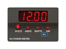
DCM20-1-DC5-R-C
Power Meter, DCM20 Series, Three Function, Voltage, Amperage, Power, Red LED, 4 Digit
⚠️ Reference pricing provided. In case of supply shortages, we will connect you with our trusted procurement partners to ensure your project's continuity.
- Manufacturer: MURATA POWER SOLUTIONS
- Product type: Digital Panel Meters
- No. of Digits / Alpha:4; Meter Function:DC Current / DC Voltage / Power; Meter Range:0A to 1200A / 0.5V to 72V / 0W to 96kW; Digit Height:9.14mm; Panel Cutout Height:22.23mm; Pan
- SVHC: No SVHC (07-Jul-2017)
- Meter Range: 0A to 1200A / 0.5V to 72V / 0W to 96kW
- Digit Height: 9.14mm
- Product Range: DCM20 Series
- Meter Function: DC Current / DC Voltage / Power
- Panel Cutout Width: 37.47mm
- Supply Voltage Max: 72VDC
- Supply Voltage Min: 9VDC
- Panel Cutout Height: 22.23mm
- No. of Digits / Alpha: 4
- Operating Temperature Max: 60°C
- Operating Temperature Min: 0°C
| Delivery and price | |
|---|---|
| Units per pack | 10 |
| Price | 68.61 € |
| Current stock | 25+ |
| Lead time | 30 days |
Datasheet

## **www.murata-ps.com**

## **DCM20 Series**

Three-Function DC Power Meters

## **PRODUCT OVERVIEW**

Murata Power Solutions’ DCM20 series DC power meters display the most critical measurements in DC-powered equipment: voltage, amperage and power. A front panel selectorswitch provides two modes of operation: a fixed reading of any of the three parameters, or a continuous cycling through all three measurements. In fixed-reading mode, the function to be displayed (V/A/W/kW) is selected by a capacitive touch sensor, avoiding the wear-out issues often seen with membrane or other mechanical control switches.

The DCM20 typically requires 6 mA of operating current at a supply voltage of 12 VDC, and only 2 mA at 72 VDC. This feature allows it to be added to existing systems with minimal electrical loading effects.

The DCM20 can be powered from a DC power supply ranging from 9 to 72 VDC. The meter supports two fundamental voltage measurement configurations. In the first configuration, the DCM20 is powered from the DC power supply line which it is monitoring. When used in this way, it can provide voltage measurements in the range of 9 - 72 VDC, as it is unpowered at lower voltages. The DCM20 may also be configured such that it is powered from a separate power supply than that which is monitoring. When used in this way, it can support voltage measurements over the entire 0.5 to 72 VDC range.

## **FEATURES**

~~|~~ Displays DC volts, amperes, watts and kilowatts. ~~a~~ Two display modes: continuous auto cycling or fixed. ~~oe~~ 9 - 72 VDC voltage operation. ~~a~~ 0.5 - 72 VDC voltage measurement range. ~~a~~ 0 -1200 A current measurement range (dependent on external shunt).

For current and power measurements, DCM20 series DC power meters require the use of an external shunt resistor. The DCM20’s wide common-mode input range (0 to 72 V) supports both high-side and low-side current sensing in a variety of applications. A 4-position DIP switch supports field selection of 16 shunt calibration factors. Additionally, a 12-turn trim potentiometer is also provided on the rear of the meter to support precision field calibration of the meter to the actual shunt value.

~~ee~~ 0 - 96 kW power measurement range. ~~a~~ Supports both high-side and low-side current monitoring.

- ~~a~~ Long-life contactless touch-sensor function selector switch.

~~ee~~ Low current consumption (< 10 mA at 12 VDC). ~~a~~ Internal self-resetting fuse ~~a~~ One-piece polycarbonate housing fits ‘0U’ & ‘1U’ racks. ~~oe~~ Compact surface mount design occupies minimal panel space.

A large (0.36 in/9.2 mm), bright LED display makes DCM20 DC power meters easily ~~a~~ One-piece polycarbonate housing fits ‘0U’ & ‘1U’ racks. readable from as far as 15 feet (5 meters). All units are packaged in a one-piece, vibration ~~oe~~ Compact surface mount design occupies minimal panel resistant, polycarbonate housing that can be installed in 0U rack components and vertical space. rack spaces as small as 1U. Their miniature size is perfect for laboratory instrumentation, ~~oe~~ Bright LED-display with four function annunciators. alternative energy applications, standby power supplies and any other products that require ~~a~~ Choice of red, green, or blue display. precise monitoring of DC voltage, current, and power.

**==> picture [540 x 250] intentionally omitted <==**

**----- Start of picture text -----**<br>
a SIMPLIFIED SCHEMATIC DIAGRAM<br>DCM20 |<br>DISPLAY<br>CURRENT-LIMITED +5 V<br>EXTERNAL POWER SOURCE DC-DC<br>| CONVERTER –5 V<br>+ |<br>L VOLTS AMPS WATTS kW<br>9 – 72 TB1 THERMAL ADC<br>VDC +V 1 FUSE J1 (VOLTAGE)<br>– –V 2 7 32<br>rile 1 ® ® &® ® |<br>MICROCONTROLLER<br>+IN 3 ADC<br>p ot) (CURRENT)<br>–IN 4 2) | |<br>+<br>+ – – SEL<br>nes EXTERNAL<br>Ge SHUNT SIGNAL SHUNT TRIM 0!<br>| CONDITIONER ADJUST TOUCH |<br>SENSOR<br>yA Or | SHUNT RANGE af "al |<br>RoHS 4209 || SELECTOR SWITCH ||<br>COMPLIANT For full details go to |<br>www.murata-ps.com/rohs<br>**----- End of picture text -----**<br>


**==> picture [91 x 10] intentionally omitted <==**

**----- Start of picture text -----**<br>
Figure 1. Simplified Schematic<br>**----- End of picture text -----**<br>


**www.murata-ps.com/support**

**MPM_DCM20Series.A01.D5** Page 1 of 6

## **DCM20 Series**

Three-Function DC Power Meters

## **Performance/Functional Specifications**

Typical at TA = +25ºC , V+ = 12 VDC unless otherwise specified

**==> picture [258 x 446] intentionally omitted <==**

**----- Start of picture text -----**<br>
Measurement Limits Min Typ Max Units<br>DC Voltage  (A) 0.5 V 72 V DC<br>DC Current  (B)<br>Range ‘1’ - 10 mΩ external shunt -5 5 A DC<br>Range ‘16’ – 41.67 µΩ external shunt -1200 1200<br>Current Shunt Differential Voltage<br>-100 +100 mV DC<br>Range  (C)<br>Current Shunt Common-mode Voltage<br>0 72 V<br>Range (D)<br>Current Fine Trim Range using Trim<br>±1%<br>Potentiometer<br>Power<br>Watts Display Mode 0 9999 W DC<br>Kilowatts Display Mode 0 96 kW DC<br>Performance<br>Display Update Rate 2.5 updates/sec.<br>Voltage Accuracy ± 1% ± 2%<br>% Full-<br>Current Accuracy ± 2% ± 3%<br>scale<br>Power Accuracy  ± 2% ± 3%<br>Temperature Drift (0 - 60) +/- 0.5 Counts/°C<br>Zero Current Reading (within 1 sec.) +/- 4 Count<br>Operating Supply Voltage 9 72 V DC<br>Operating Supply Current  (E)<br>12 V operation 6 10 mA<br>72 V operation  2 5<br>Display<br>4 Digit LED, 9.14 mm (0.36 in) Height<br>Display Type and Size 4 LED Annunciators (‘Volts,’ ‘Amps,’<br>‘Watts,’ ‘kW’)<br>Over-range Indication Flashing Display<br>Decimal Point Selection Automatically Set<br>TB1 Terminal Block<br>Copper Wire<br>Wire Size 14-24 AWG<br>Insulation Strip Length 6mm (0.24 in)<br>Screw Tightening Torque 4.6 in - lb (0.51 N-m)<br>Physical/Environmental<br>Operating Temperature 0 +60 °C<br>Storage Temperature -40 +75 °C<br>Humidity (non-condensing) 0 85 %<br>Dimensions See fgure 6<br>Unit Weight:                       1.02 oz / 29g<br>Net Package Weight:      12.28 oz / 348g<br>Weight<br>Gross Package Weight:   22.05 oz / 625g<br>Hex Nut Tightening Torque 20 in - oz (0.14 N-m)<br>**----- End of picture text -----**<br>


(A) Voltage measured across +V (TB1-1) and –V (TB1-2) OR +IN (TB1-3) and –V (TB1-2) terminals.

(B) Current measurement range dependent on external shunt selection.

(C) Applied to +IN (TB1-3) and –IN (TB1-4) terminals.

(D) Voltage applied across +IN (TB1-3) and –V (TB1-2) terminals.

(E) Current drawn by +V (TB1-1) terminal when operating voltage applied across +V (TB1-1) and –V (TB1-2) terminals.

## **ORDERING INFORMATION**

|**ORDERING INFORMATION**|**ORDERING INFORMATION**|
|---|---|
|**DCM20-1-DC5-R-C**|(Red Display)|
|**DCM20-1-DC5-G-C***|(Green Display)|
|**DCM20-1-DC5-B-C***|(Blue Display)|


*Consult factory for availability

## **TECHNICAL NOTES**

- **IMPORTANT!** To ensure safe and reliable operation, DCM20 power

- ! meters must be installed and serviced by qualified technical personnel. Contact Murata Power Solutions if there is any doubt regarding their installation or operation.

**1. Measurement Type:** DCM20 series multifunction DC power meters employ precision ADCs and a low-power microcontroller to measure and display DC voltage, current and power. The choice of measurement is selectable through the front panel. The meters measure DC current using an external series shunt resistor which is inserted into the circuit to be measured. Because the DCM20 has a wide common-mode input range (0 - 72 VDC), the shunt resistor may be inserted into either the high-side (supply) or the low-side (return) of the circuit being monitored.

DC Voltage may be monitored either at the meter’s **+IN** (TB1-3) input terminal or at the meter’s **+V** (TB1-1) power input terminal, based on the setting of jumper block **J1** . The choice of voltage monitoring input is selected based on the application requirements.

   - The DCM20 derives its DC power measurement by multiplying the measured current by the measured voltage. Power is always reported as a positive quantity, regardless of the polarity of the measured current. ( Power = | Voltage × Current | ).

**2. Basic Operation** : Upon first application of power to the meter, the unit will first perform a self-test routine and then continuously display DC volts with the VOLTS LED annunciator illuminated. The display will remain in the VOLTS mode as long as the front panel ‘SEL’ button is not touched. After the unit powers up to normal operation in the VOLTS reading mode, momentarily (approximately one second) touching the ‘SEL’ button on the unit’s front panel twice in succession will cycle the display to AMPS, and then to WATTS (or kW, depending on the power measurement value). Momentarily touching ‘SEL’ a third time will return the display back to the VOLTS reading mode. Holding the ‘SEL’ button down for 5 seconds will place the unit in a continuous auto-cycling mode, and the display will repetitively scroll through all three measurements, with each measurement remaining displayed for 3 seconds.

When the continuous auto-cycling mode is initially selected, the unit will briefly display ‘Auto On’ before continuous cycling begins. Momentarily touching the ‘SEL’ button again will cause the unit to briefly display ‘Auto OFF’ before it returns to the fixed VOLTS reading mode.

The power-up default display mode (Volts/Amps/Watts/Auto-cycle) may be selected by simply leaving the DCM20 in a given display mode for 60 seconds or more. The next time the meter powers up, it will do so in the new default mode. The default mode may be reset by selecting a new operating mode and leaving the meter in that mode for 60 seconds or longer.

**3. Calibration:** The DCM20’s voltage measurement function is factorycalibrated and cannot be field-calibrated. Because the meter is designed to work with a wide range of shunt resistors for current measurement, however, field configuration and fine adjustment of the current measurement function is supported. The DCM20’s shunt scaling factor is selected by a 4-position DIP switch SW1 on the rear of the unit (refer to figure 9, Mechanical Specifications). A total of 16 ranges are supported. Table 1 lists supported current ranges and their associated switch settings, and also includes recommended Murata shunt resistors for selected ranges. Additionally, a trimmer potentiometer on the rear of the unit supports fine adjustment of the shunt scaling factor to accommodate tolerance errors

**www.murata-ps.com/support**

**MPM_DCM20Series.A01.D5** Page 2 of 6

**DCM20 Series**

## Three-Function DC Power Meters

in the shunt value. Because adjusting the meter using this potentiometer requires that the DCM20 be powered up and measuring current, this operation should only be performed by qualified personnel using an insulated adjustment tool.

**Table 1. Shunt Range Selection**

|**Range **<br>~~|~~|**SW1 Setting**<br>~~moe]~~|**SW1 Setting**<br>~~moe]~~|**SW1 Setting**<br>~~moe]~~|**Full-scale**<br>**Current**<br>**Range (A)**<br>~~moe]~~<br>~~|~~|**Full-scale**<br>**Power**<br>**Range**|**Shunt**<br>**Voltage**<br>**(mV)**|**Recommended**<br>**Murata Shunt**<br>**Resistor P/N**|
|---|---|---|---|---|---|---|---|
|1<br>~~|~~<br>~~a~~|1<br>~~moe]~~<br>~~a~~|~~moe]~~<br>~~a~~|~~moe]~~|5.000<br>~~moe]~~<br>~~|~~<br>~~|~~|400.0 W<br>~~|~~|50|3020-01097-0|
|2<br>~~| ~~<br>~~fm]~~<br>~~a~~|1<br> ~~moe]~~<br>~~fm]~~<br>~~a~~|~~moe]~~<br>~~fm]~~<br>~~a~~|~~moe]~~<br>~~fm]~~|10.00<br>~~moe]~~<br>~~|~~<br>~~fm]~~<br>~~|~~<br>~~ee~~|800 W<br>~~fm]~~<br>~~|~~<br>~~ee~~|100<br>~~fm]~~<br>~~ee~~|3020-01107-0<br>~~fm]~~|
|3<br>~~a~~|1<br>~~a~~|~~a~~||20.00<br>~~|~~<br>~~ee~~|1600 W<br>~~|~~<br>~~ee~~|50<br>~~ee~~|3020-01098-0|
|4<br>~~a~~<br>~~al~~|1<br>~~a~~<br>~~al~~|~~a~~<br>~~al~~|~~al~~|50.00<br>~~|~~<br>~~ee ~~<br>~~al~~<br>~~ee~~|4000 W<br>~~|~~<br> ~~ee ~~<br>~~al~~<br>~~ee~~|50<br> ~~ee~~<br>~~al~~<br>~~ee~~|3020-01096-0<br>~~al~~|
|5<br>~~al~~<br>~~a~~|1<br>~~al~~<br>~~a~~|~~al~~<br>~~a~~|~~al~~<br>~~a~~|50.00<br>~~al~~<br>~~a~~<br>~~ee~~<br>~~ee~~|4000 W<br>~~al~~<br>~~ad~~<br>~~ee~~|100<br>~~al~~<br>~~d~~<br>~~ee~~|--<br>~~al~~<br>~~d~~|
|6<br>~~a~~<br>~~a~~|1<br>~~a~~<br>~~a~~|~~a~~<br>~~a~~|~~a~~<br>~~a~~|75.00<br>~~a~~<br>~~ee ~~<br>~~a~~<br>~~ee~~|6000 W<br>~~ad~~<br> ~~ee ~~<br>~~a~~|50<br>~~d~~<br> ~~ee~~<br>~~a~~|--<br>~~d~~<br>~~a~~|
|7<br>~~a~~<br>~~ell~~<br>~~a~~|1<br>~~a~~<br>~~ell~~<br>|~~a~~<br>~~ell~~<br>~~ad~~|~~a~~<br>~~ell~~<br>~~ad~~|100.0<br>~~a~~<br>~~ee~~<br>~~ell~~<br>~~ad~~|8000 W<br>~~a~~<br>~~ell~~<br>~~ee~~|50<br>~~a~~<br>~~ell~~<br>~~ee~~|3020-01099-0<br>~~a~~<br>~~ell~~|
|8<br>~~a~~<br>~~|~~|1<br><br>~~Maw}~~|~~ad~~<br>~~Maw}~~|~~ad~~<br>~~Maw}~~|100.0<br>~~ad~~<br>~~Maw}~~<br>~~|~~|8000 W<br>~~ee~~|100<br>~~ee~~|3020-01108-0|
|9<br>~~a ~~<br>~~|~~|1<br> <br>~~Maw}~~|~~ad~~<br>~~Maw}~~|~~ad~~<br>~~Maw}~~|150.0<br>~~ad~~<br>~~Maw}~~<br>~~|~~<br>~~ee~~|2.00 kW<br>~~ee~~<br>~~ee~~|50<br>~~ee~~<br>~~ee~~|3020-01100-0|
|10<br>~~| ~~<br>~~e~~|1<br> ~~Maw}~~<br>~~e~~|~~Maw}~~<br>~~e~~|~~Maw}~~<br>~~e~~|200.0<br>~~Maw}~~<br>~~|~~<br>~~e~~<br>~~ee~~|6.00 kW<br>~~ed~~<br>~~ee~~|50<br>~~d~~<br>~~ee~~|3020-01101-0<br>~~d~~|
|11<br>~~e~~<br>~~pt~~|1<br>~~e~~<br>~~ptAA]~~|||300.0<br>~~e~~<br>~~ee ~~<br>~~AA]OP~~|24.00 kW<br>~~ed~~<br> ~~ee ~~<br>~~OP~~|50<br>~~d~~<br> ~~ee~~|3020-01102-0<br>~~d~~|
|12<br>~~pt~~<br>~~la~~|1<br>~~pt~~<br>~~la~~|~~AA]~~<br>~~la~~|~~AA]~~|400.0<br>~~AA]OP~~<br>~~ee~~|32.00 kW<br>~~OP~~<br>~~ee~~|50<br>~~ee~~|--|
|13<br>~~pt~~<br>~~la~~<br>~~eal~~|1<br>~~pt~~<br>~~la~~<br>~~eal~~|~~AA]~~<br>~~la~~<br>~~eal~~|~~AA]~~<br>~~eal~~|500.0<br>~~AA]OP~~<br>~~ee~~<br>~~eal~~|40.00 kW<br>~~OP~~<br>~~ee~~|50<br>~~ee~~|3020-01103-0|
|14<br>~~pt~~<br>~~la~~<br>~~eal~~|1<br>~~pt ~~<br>~~la~~<br>~~eal~~|~~AA]~~<br>~~la~~<br>~~eal~~|~~AA]~~<br>~~eal~~|800.0<br>~~AA] OP~~<br>~~ee ~~<br>~~eal~~|64.00 kW<br>~~OP~~<br> ~~ee ~~|50<br> ~~ee~~|3020-01104-0|
|15<br>~~eal~~<br>~~pf~~|1<br>~~eal~~<br>~~pf~~|~~eal~~<br>~~pf~~|~~eal~~<br>|1000<br>~~eal~~<br>~~fp~~|80.00 kW<br>~~fp~~|50<br>~~fp~~|3020-01105-0<br>~~fp~~|
|16<br>~~pf~~|1<br>~~pf~~|~~pf~~||1200<br>~~fp~~|96.00 kW<br>~~fp~~|50<br>~~fp~~|3020-01106-0<br>~~fp~~|


**4. Shunt Selection:** Table 1 lists recommended current shunts available from Murata Power Solutions for current ranges supported by the DCM20. Please note that a given shunt may not necessarily support continuous operation at the extreme limits of its measurement range. The maximum current that a shunt may be safely operated at is also highly dependent on application conditions such as ambient temperature, airflow and mounting position. Before selecting and installing a shunt, you should refer the shunt’s datasheet for details on correct operation.

5. Jumper Configuration: The setting of jumper **J1** determines the source of voltage to be measured. When the shorting block is placed over posts J1-1 and J1-2, the DCM20 measures the voltage between the **+IN** (TB13) connector terminal and the **-V** (TB1-2) connector terminal. When the shorting block is placed over posts J1-2 and J1-3, the DCM20 measures the voltage between the **+V** (TB1-1) and **-V** (TB1-2) connector terminals. The meter must have the shorting block placed on jumper **J1** for normal operation. Jumper block **J1** is located on the rear of the meter as shown in figure 9 (mechanical drawing). The DCM20 is shipped with the shorting block placed across jumper pins J1-2 and J1-3.

**6. Wiring:** Power supply and input wiring must be rated for the electrical and environmental conditions under which the meter will be operated. They must also comply with any regulatory or application-mandated

requirements pertaining to the user’s installation. Connections to DCM20 meters must be made with all power sources de-energized. Refer to the Functional Specifications section for detailed wire type and wire gauge information.

Wiring insulation should be stripped to 6 mm (0.24 in). All wires must be inserted into the terminal block openings such that the screw terminal does not pinch any insulation. After final assembly, inspect all terminal block connections for shorts between adjacent conductors; this step is particularly important when using stranded wire.

**7. Protection and Fusing:** DCM20 meters’ power supply leads are protected against momentary overvoltage (( **+V** - **-V** ) > 72 V) and reverse polarity conditions (( **+V** - **-V** ) < 0 V ). The **+V** (TB1-1) power supply line is also protected with an internal self-resetting thermal fuse. The meter’s **+IN** (TB1-3) and **–IN** (TB1-4) terminals are protected against brief voltage transients. Neither set of inputs is protected against sustained conditions exceeding the limits listed in in the Performance & Functional Specifications table. External fusing must be supplied by the user in accordance to applicable safety and regulatory requirements for the system in which the DCM20 is installed.

**8. Shunt Polarity:** While the external current shunt has no intrinsic ‘polarity’, the way in which it is connected into the circuit being measured will influence the polarity of current as measured by the meter. The relationship between current direction and meter reading is shown in figure 2.

**==> picture [193 x 110] intentionally omitted <==**

**----- Start of picture text -----**<br>
SHUNT VOLTAGE SHUNT VOLTAGE<br>+ – – +<br>_<br>i +IN -_ –IN ° +IN a –IN<br>aau -Jau<br>VOLTS AMPS WATTS kW VOLTS AMPS WATTS kW<br>oot ssc<br>METER READS METER READS<br>POSITIVE AMPS NEGATIVE AMPS<br>**----- End of picture text -----**<br>


Figure 2. Relationship between shunt voltage polarity and meter reading

**9. Terminal Block Wire Size & Torque Ratings:** It is important to tighten all screw-terminals to their torque specification of 4.5 in - lb (0.51 N-m). Proper tightening will help ensure reliable operation. Applications subject to vibration should use stranded wire.

**10. Typical Wiring Diagrams:** The DCM20 is a flexible voltage, current, and power measurement device, supporting both high-side and low-side shunt configurations. This section describes four of the most common ways in which the DCM20 may be used.

In figure 3, the current shunt is inserted into the load’s positive supply line, which is known as high-side measurement. The DCM20 is also powered from this line. In this configuration the shorting block on jumper **J1** should be connected across pins J1-1 and J1-2. Because the meter is powered from the line being monitored, useful measurements can only be made on DC line voltages in the range of 9 - 72 VDC, as at lower voltages the meter will not be powered. In this configuration, the DCM20 measures the sum of both the load power and the power dissipated by the shunt.

**www.murata-ps.com/support**

**MPM_DCM20Series.A01.D5** Page 3 of 6

**DCM20 Series**

Three-Function DC Power Meters

**==> picture [166 x 130] intentionally omitted <==**

**----- Start of picture text -----**<br>
DCM20<br>TB1<br>+V<br>I w 1 ft<br>+ –V<br>2<br>DC +IN m |() 3 —<br>SUPPLY J1<br>9 - 72 VDC –IN<br>4<br>1 2 3<br>–<br>+ – + LOAD –<br>SHUNT<br>**----- End of picture text -----**<br>


Figure 3. High-side current measurement, meter powered from DC line

Figure 4 shows the case where current is also measured at the highside of the load but the meter is powered from an independent supply. Because the meter is now independently powered, it can now measure voltage and power over the full range of 0.5 to 72 VDC. In this configuration the shorting block on jumper **J1** should be connected across pins J1-1 and J1-2 so that the meter measures the voltage at the **+IN** (TB1-3) terminal. In this configuration, the meter measures the sum of both the load power and the power dissipated by the shunt resistor.

**==> picture [171 x 130] intentionally omitted <==**

**----- Start of picture text -----**<br>
DCM20<br>+<br>TB1<br>METER<br>SUPPLY +V 1<br>9 - 72 VDC<br>7 – –V am C)y 2<br>+IN<br>/ O|/m 3 J1<br>– –IN 4<br>1 2 3<br>LOAD<br>SUPPLY<br>72 V MAX<br>+<br>+ – + LOAD –<br>SHUNT<br>**----- End of picture text -----**<br>


Figure 4. High-side current measurement, independent meter supply

Figure 5 shows a high-side shunt configuration in which the power dissipated by the shunt is excluded from the measurement. In this case, the meter’s **+V** (TB1-1) terminal is connected to the **-IN** (TB1-4) terminal and the meter both derive power and the voltage measurement from this point in the circuit. Measuring voltage through the **+V** (TB1-1) pin requires that the shorting block be connected across pins J1-2 and J1-3 of jumper **J1** . Because the meter requires very little operating power, its addition to the load will typically influence neither the current nor power measurements to a significant degree.

Figure 6 shows a configuration where the shunt is inserted into the load return line and measures the current through that connection. In this case, the meter must be powered from the DC line though the **+V** (TB1-1) input, as the **+IN** (TB1-3) input only detects the voltage across the shunt (< 100 mV). For this reason the jumper shorting block should be placed across pins J1-2 and J1-3 of jumper **J1** to enable measurement of voltage from the **+V** (TB1-1) input. The total power reported in this configuration is the sum of the load power plus the shunt power dissipation.

**==> picture [173 x 298] intentionally omitted <==**

**----- Start of picture text -----**<br>
DCM20<br>TB1<br>+V<br>–V B 3w 1 *<br>2<br>= +IN a 3<br>a i J1<br>–IN<br>4<br>1 2 3<br>+ –<br>+ SHUNT +<br>POWER<br>SUPPLY LOAD<br>9 - 79 VDC<br>– –<br>Figure 5. High-side current measurement, shunt power excluded<br>DCM20<br>+<br>+ LOAD TB1<br>POWER +V<br>9 - 72 VDCSUPPLY – –V 1<br>2<br>– + +IN<br>3<br>SHUNT rol L –IN ma 0i) 4 ” J1<br>– 1 2 3<br>an -<br>**----- End of picture text -----**<br>


Figure 5. High-side current measurement, shunt power excluded

Figure 6. Low-side current measurement

**Table 2. J1 Jumper Settings***

|**Measurement Configuration**|**Figure**<br>**M**|**Voltage**<br>**Measured at . .**|**Jumper**<br>**Across Pins**|
|---|---|---|---|
|High-side current measurement|3|**+IN(TB1-3)**|1-2|
|High-side current measurement,<br>independentmetersupply|4|**+IN (TB1-3)**|1-2|
|depesuppy<br>High-side current measurement,<br>shunt power excluded|5|**+V(TB1-1)**|2-3|
|Low-side current measurement|6|**+V(TB1-1)**|2-3|


*Product shipped with jumper across pins 1 and 2.

**11. Noisy Power Supplies:** Some power supplies contain high-frequency switching devices that may conduct and/or radiate significant noise onto the low-level signal developed across the internal shunt. Even though DCM20 ammeters incorporate built-in input filtering, some portion of this noise may be amplified and subsequently measured by its sensitive input circuitry. The amplified noise introduces errors that are particularly noticeable at zero load current (i.e., the ammeter function may not display a relatively steady “000” reading). Connecting an external, non-polarized capacitor across the +IN and -IN inputs can help reduce noise-related display errors. In certain situations, the use of twisted pair or shield wiring may be required. As a general rule, avoid using excessively long leads between the shunt and the meter’s **+IN** (TB1-3) and **–IN** (TB1-4) inputs.

**www.murata-ps.com/support**

**MPM_DCM20Series.A01.D5** Page 4 of 6

## **DCM20 Series**

Three-Function DC Power Meters

## **PANEL INSTALLATION**

All connections to DCM20 power meters must be made after the unit is securely attached to the panel and with all associated load and supply voltages de-energized (off), using extreme caution and observing all safety measures applicable to the user’s installation.

The installed wire-positions should be such that minimal mechanical forces are applied to TB1 or to the DCM20 power meter itself. In highvibration environments, it is strongly recommended that adequate strain reliefs be used for all wiring.

Using figure 7 as a guide, carefully insert the DCM20 assembly into the panel opening. From the rear of the panel, install and then tighten the

four #2-56 hex nuts over the threaded studs. **Tighten each nut to 15 to 20 in - oz (0.106 to 0.140 N-m).** Use only the factory-supplied hardware as the use of substitute hardware could result in an unsafe installation and/or adversely affect the reliability of the installation.

The recommended range of panel thickness that can be used with the supplied hardware is 0.040 in (1.0 mm) to 0.25 in (6.4 mm). Panel thicknesses outside of this range may require additional user-supplied hardware or modifications. Refer to the panel cutout drawing (figure 8) for recommended drill and cutout dimensions.

**==> picture [93 x 9] intentionally omitted <==**

**----- Start of picture text -----**<br>
PANEL INSTALLATION<br>**----- End of picture text -----**<br>


## **PANEL CUTOUT**

**==> picture [527 x 225] intentionally omitted <==**

**----- Start of picture text -----**<br>
Mounting Panel #2 Flat Washer (4) 4x 0.093±0.003 2.36±0.08<br>1.626 41.30<br>#2 Lock Washer (4) CL<br>DCM20 Panel Meter<br>2-56 Hex Nut (4)<br>Torque each nut to 15-20 in - oz<br>[0.106-0.140 N-m] 0.875 22.23 CL 1.070 27.18<br>V W t— Vf oo<br>1 1.475 37.47<br>E TE<br>Figure 8. Recommended panel cutout dimensions<br>Dimensions are in Inches [mm]<br>Figure 7. Panel installation Tolerances (Unless Otherwise Specified)<br>Panel Cutout<br>**----- End of picture text -----**<br>


2 Place 0.02 [0.5] 3 Place 0.010 [0.25]

## **1. Description of safety marks:**

Caution, risk of electrical shock

Caution, risk of danger

Equipment is protected throughout by double or reinforced insulation

**2. Cleaning Instructions: Gently clean with dry cloth only.**

**3. Caution: if the equipment is used in a manner not specified by Murata Power Solutions, the protection provided by the equipment may be impaired.**

**www.murata-ps.com/support**

**MPM_DCM20Series.A01.D5** Page 5 of 6

## **DCM20 Series**

## Three-Function DC Power Meters

## **MECHANICAL SPECIFICATIONS**

**==> picture [485 x 494] intentionally omitted <==**

**----- Start of picture text -----**<br>
2.10 53.3 0.51 13<br>ee<br>1.43 a 36.3 FO<br>Cnene n e B<br>0.35 8.9<br>Front View ne<br>Side View<br>Pp o A A A A<br>yf<br>0.40 10.1<br>_ \) OM 1.626 _ 41.30<br>Centered<br>2-56-UNC-2A Studs (4)<br>Bottom View SW1 TB1<br>1 JP1<br>4<br>2<br>THIRD ANGLE PROJECTION 3 3 2 1 3 1.070 27.18<br>4<br>2 Centered<br>R4<br>Oc mou 1<br>(oral i E<br>(Current Trim)<br>Components are shown for Ref Only<br>Dimensions are in Inches [mm]<br>Rear View<br>Tolerances (Unless Otherwise Specified)<br>2 Place 0.02 [0.5]<br>3 Place 0.010 [0.25]<br>O<br>N<br>**----- End of picture text -----**<br>


Figure 9. Mechanical specifications

Murata Power Solutions, Inc. ISO 9001 and 14001 REGISTERED

**This product is subject to the following operating requirements and the Life and Safety Critical Application Sales Policy: Refer to: http://www.murata-ps.com/requirements/**

Murata Power Solutions, Inc. makes no representation that the use of its products in the circuits described herein, or the use of other technical information contained herein, will not infringe upon existing or future patent rights. The descriptions contained herein do not imply the granting of licenses to make, use, or sell equipment constructed in accordance therewith. Specifications are subject to change without notice. _**© 2018 Murata Power Solutions, Inc.**_

## **www.murata-ps.com/support**

**MPM_DCM20Series.A01.D5** Page 6 of 6
Updated at June 9, 2026
About Novapart
Novapart is a B2B electronic component broker specialising in stock shortages and cost reduction. We source hard-to-find parts and identify compliant alternatives across a catalogue of 410,000+ components from 500+ manufacturers.
Learn more →Stock Shortage Specialist
When a component is unavailable, discontinued or has an unacceptable lead time, we tap into our network of vetted European and Asian distributors to source what you need — without compromising on quality or traceability.
Request a quote →Compliant Alternatives
We identify pin-to-pin, electrically equivalent substitutes that meet the same certifications (RoHS, AEC-Q100, REACH) as your original specification — validated against datasheets, not just part numbers. Often at a lower cost.
BOM Analysis service →