
Image not available
Illustrative purposes only

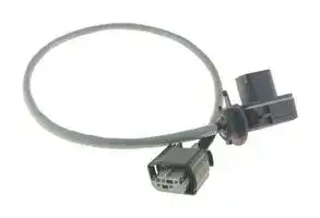
BLD_ADAPTER_24/12
Cable Assembly, Connector & Digital 24 to 12V Adaptor, BLD Series Battery Leak Detection Sensors
⚠️ Reference pricing provided. In case of supply shortages, we will connect you with our trusted procurement partners to ensure your project's continuity.
- Manufacturer: AMPHENOL SGX SENSORTECH
- Product type:
- SVHC: No SVHC (27-Jun-2024)
- For Use With: SGX Sensortech BLD Series Battery Leak Detection Sensors
- Accessory Type: Cable Assembly w/ Connector & Digital 24 to 12V Adaptor
| Delivery and price | |
|---|---|
| Units per pack | 1 |
| Price | 26.44 € |
| Current stock | 10+ |
| Lead time | 30 days |
Datasheet

**Safety**

**Industrial Health Agriculture**

## **INIR2-BU1.8**

## **Butane sensor** Datasheet

The **INIR2-BU1.8** is a user-friendly digital Gas Sensor, which is designed to use the latest SGX Sensortech’s non-dispersive

functionality. It incorporates the latest electronics and offers a linear output proportional to the gas concentration applied. Temperature compensation, good accuracy, low voltage DC power supply and simple implementation into end-user system

_Quality, Safety, Responsibility_

SGX Europe Sp. z o.o. T: +48 (0) 32 438 4778 Konduktorska 42 St., 40-155 Katowice, E: sales.is@sgxsensortech.com Poland www.sgxsensortech.com

## **Functional specifications**

|**Power Supply**<br>re<br>es|**Min**<br>ee<br>ee|**Typical**<br>eee<br>ee|**Max**<br>ee|
|---|---|---|---|
|Supply Voltage<br>re <br>es<br>ee<br>enampton|b|3.2 VDC<br> ee<br>ee<br>ee<br>|b|3.3 VDC<br>eee<br>ee<br>ee<br>|b1|5.25 VDC<br>ee<br>1|
|Average Current<br>es <br>ee<br>enampton|b|30mA<br> ee<br>ee<br>|b|32mA<br>ee<br>ee<br>|b1|35mA*<br>1|
||*Inrush Current can be up to 60mA<br>ee ee<br>|b1|||
|Logic Outputs Level<br>enampton |b|LOW Voltage Level (VOL):<br>0.6V Maximum<br>HIGH Voltage Level (VOH):<br>2.0V Minimum<br>1.6mA source current maximum<br>|b 1|||
|Logic Inputs Level|LOW Voltage Level (VIL): 0.4V Maximum<br>HIGH Voltage Level (VIH): 2.0V Minimum|||
|**Humidity**<br>OperatingHumidity|<br>|||||
|OperatingHumidity|<br>rs|0%<br>|<br>|<br>ee|50%<br>ee|99%<br>eee|
|Storage Humidity<br>OperatingHumidity |<br>rs|0%<br>|<br>|<br>ee|50%<br>ee|90%<br>eee|
|**Temperature**<br>rs<br>ee<br>ee eee<br>OperatingTemp.Pe||||
|OperatingTemp.Pe|-40°C to 75°C<br>Pe|||
|Storage Temp.<br>OperatingTemp. Pe|-20°C to 55°C<br>Pe|||
|Temp. Cycle Limits||0.8°C/min|1.3°C/min|
|**Pressure**<br>;||||
|;<br>Operating Pressure||80kPa - 120kPa<br>||||
|Storage Pressure|80kPa - 120kPa|||
|**Output Signal**||||
|Analogue Output<br>i|Resolution: 12-Bit at 0.0-2.5 Volts DC Max|||
|UART<br>**Signal**<br>**format**<br>**Baud**<br>**rate**<br>i|8 data bits, 2 stop bit, no parity|||
||38400 as default, 115200, 19200, 9600|||
|Technicalspecifications||||
|Body Material<br>Technical specifications|Stainless Steel<br>specifications|||
|Weight|25 g|29 g|33 g|
|**Gas Sensor Sockets**||||
|S1|5-Pin , Polygon Topology|||


## **Features**

**==> picture [217 x 242] intentionally omitted <==**

**----- Start of picture text -----**<br>
• 0-1.8% volume.<br>• Gas Sensor with between ranges,<br>Automatic Switchover<br>• up to 20ppm,<br>High Resolution<br>• at 100ppm,<br>•<br>Analog Output of gas concentration,<br>• UART ),<br>• Full &<br>• Cyclic Redundancy Check ( CRC )<br>• Typical Low power consumption < 100mW (Average)<br>• Factory calibrated  for up to 1.8% Butane<br>• Evaluation Kit available including PC software for easy<br>• Design for use in Hazardous Areas<br>• Certified for use in Explosive Atmospheres (EX)<br>• Agriculture<br>• Automation & Control<br>**----- End of picture text -----**<br>


- **Indoor Air Quality**

- **Industrial Health & Safety**

- **Waste Management**

## ~~a~~ **Pin Configuration**

## **(Dimensions in mm)**

**==> picture [273 x 98] intentionally omitted <==**

**----- Start of picture text -----**<br>
0.42<br>@ 20.00 I]<br><6: 2<br>3.38<br>nell 1.50 =<br>@ 13.80 4.24<br>16.60<br>0.8 10.67 5.08<br>4.80<br>**----- End of picture text -----**<br>


|**Pin**<br>~~feescinfon~~|**Name**<br>~~feescinfon~~|~~feescinfon~~|
|---|---|---|
|1<br>~~feescinfon~~|TXD<br>~~feescinfon~~|Data transmitted from the Integrated IR.<br>~~feescinfon~~|
|2|VIN|3.2 Volts – 5.25 Volts DC input to Integrated IR|
|3|GND|GND Plane, 0 Volts reference for Integrated IR|
|4|RXD|Data received by the Integrated IR.<br>Analog<br>Output.<br>Scalable<br>range,<br>see|
|5<br>a|OUT|Analog<br>Output.<br>Scalable<br>range,<br>see<br>Application Note 1 Integrated IR Protocol &<br>Calibration for details.|
|Pad<br>a|Pad|Bootloader Pad. Not used by the customer.|
|Not used by the customer.<br>Note 1: All Dimensions in mm. All tolerances Linear +/- 0.1mm and<br>Angular 0.5° unless otherwise stated.<br>Note 2: Pins height 4.8 (+/- 0.8mm)<br>Note 3:<br>DO NOT SOLDER PINS. Use sockets to push-fit the sensor in<br>the instrument. Please refer to our handling precautions on page 4.<br>Note 4: SGX Sensortech recommends the Wearns Cambion type<br>450-1813-01-03-00 single-pole solder mount socket with through hole,<br>or a suitable equivalent.<br>a|||


Note 2: Pins height 4.8 (+/- 0.8mm) Note 3: DO NOT SOLDER PINS. Use sockets to push-fit the sensor in the instrument. Please refer to our handling precautions on page 4. Note 4: SGX Sensortech recommends the Wearns Cambion type 450-1813-01-03-00 single-pole solder mount socket with through hole, or a suitable equivalent.

DS-0463-INIR2-BU1.8, Issue 2, 17-Oct-2023, Page 1/4

© SGX Sensortech 2012-2023

SGX Europe Sp. z o.o. Konduktorska 42 St., 40-155 Katowice, Poland

T: +48 (0) 32 438 4778 E: sales.is@sgxsensortech.com www.sgxsensortech.com

## **Design Considerations & Applications**

## **Warm-Up Time**

The Warm-Up Time for the INIR2 sensor is 45 seconds after each power “ON” or every time when we are changing from Configuration to Normal/Engineering Mode. During this time data are not valid. Please read Fault codes in Application Note 1, “Integrated IR Protocol & Calibration”.

The Warm-Up time is not including the period that the sensor needs to reach the ambient temperature. The sensor though is capable of producing readings during the Warm-Up but with a much higher error than specifications.

## **Calibration**

For calibration process please read the appropriate Application Note 1, “Integrated IR Protocol & Calibration”.

For optimum performance please use following cylinders:

INIR2-BU1.8 (Butane) 100% Nitrogen or air for Zero calibration 0.9% C4H10 (50%LEL) for High Span Cal.

Always do Zero Calibration first followed by High Span.

## **Gas Flow Rate**

For valid evaluation and to keep tests consistent it is recommended to use 450 – 500 cc/min. flow rate to minimize any effects due to pressure variations in the INIR2.

## **Digital Interface/Communication**

To read-out the digital output from the sensor, a Microcontroller (MCU) or Personal Computer (PC) is required. The software with our Evaluation kit is compatible with Windows Operating System only and at the moment is not possible to read the Analogue output by using the Evaluation Software.

## **Analogue Output**

The Analogue Output is updated once per second. Analogue voltage is directly related with measurement range and current concentration.

## **Faults Monitoring/Error States**

The Error monitoring and Fault generation happens every second transmitted by the UART. Regularly check all the Faults generated from the INIR2 to ensure errorless communication and rise appropriate alarms depending on the Fault code. For further information on the different Faults and how to translate them, please read the Application Note 1, “Integrated IR Protocol & Calibration”.

## **Condensation Compensation, Dust & Extreme Conditions**

Using the INIR2 in extreme environmental conditions may affect its performance. Typically, the module has a high corrosion resistance and temperature compensated linearized output. The INIR2 implements a Condensation Compensation Algorithm to minimize the effect especially after power “ON”, eliminating the problem with false alarm. The Sensor can withstand multiple thermal shocks that don’t exceed 1.3°C/min temperature slopes. In applications like mining where dust or other particles are present is recommended to use a dust filter firmly attached to the inlet of the INIR2 Gas Sensor. The filter tends to increase response times T90, T10 and T50 therefore ensure correct installation and evaluation to comply with regulations in your country. If your device is intended to be used in a hazardous environment, please seek advice from a certification body.

## **Pressure Compensation**

The INIR2 will need pressure compensation irrelevant if the pressure is within the operating pressure range. Re-Zero the INIR2 Gas Sensor under operating conditions is recommended; this will minimize the pressure effects, temperature differential effects but will not eliminate the weather effects like extreme wind velocity, rain or lighting.

## **Certifications Details**

**==> picture [536 x 232] intentionally omitted <==**

**----- Start of picture text -----**<br>
|||||
|---|---|---|---|
|ATEX|IECEx|
|OBAC 22 ATEX 0196U|IECEx OBAC 20.0006U|
|a|ae|
|Standards|EN 60079-0, IEC 60079-1|IEC 60079-0, IEC 60079-1|
|I M2 Ex db I Mb|Ex db I Mb|
|Product Marking|1461|II 2G Ex db IIC Gb|Ex db IIC Gb|
|Power Input:|1.5W Maximum|Ambient temperature range:|-40°C to +75°C|
|Condition 1:|The thermal resistance of the Gas Sensing Heads do not exceed 25K/W. This shall be taken into|
|account when considering its surface temperature and the temperature classification of the equiment into|
|which it is to be incorporated. Tests indicated that an internal ignition increases the temperature of the mesh by|
|further 4.2K (including a 1.2 safety factor).|
|Special Conditions|
|for Safe Use|Condition 2:|The Gas Sensing Heads shall be protected from impact in service. The Gas Sensing Head shall|
|be mounted in a protective enclosure such that an impact of 7 J in accordance with IEC 60079-0:2007 clause|
|26.4.2 from any direrction shall not cause the impact head to make contact with the Sensing Head.|
|Condition 3:|The Gas Sensing Heads are dust-proof (IP5X) but offers no protection against the ingress of|
|water. Where protection in excess of IP50 is required, then the apparatus into which the Gas Sensing Head is|
|installed shall provide the necessary ingress protection (for example by fitting an external semi-permeable|
|membrane).|
|Manufacturing &|
|SGX Europe sp. z o. o., 40-155 Katowice, 42 Konduktorska St., POLAND|
|Certificate Address|

**----- End of picture text -----**<br>


## **Typical performance characteristics**

(All Data are related to a calibrated sensor and conditions: Temperature 20°C, Relative Humidity 10%RH, Pressure 101kPa, 500 to 1000 ml/min Gas Flow, Averaging of 20 values, unless otherwise stated.)

**==> picture [341 x 122] intentionally omitted <==**

**----- Start of picture text -----**<br>
Voltage regulator<br>3.3-5V L1 742792133 F1<br>Vin Vin Vout<br>=] GND 125mA VCC<br>TXD<br>GND C110uF D1SP1003-01DTG _ TXD SS  {¢ ) K 23 e 6 U1AD8628ARZAnalog Output<br>GND GND GND GND<br>RXD<br>GND<br>GND<br>1 7<br>2<br>4<br>**----- End of picture text -----**<br>


Fig. 1 Example schematic for Interfacing Integrated IR (INIR2-BU1.8)

DS-0463-INIR2-BU1.8, Issue 2, 17-Oct-2023, Page 2/4

© SGX Sensortech 2012-2023

E: sales.is@sgxsensortech.com www.sgxsensortech.com

SGX Europe Sp. z o.o. T: +48 (0) 32 438 4778 Konduktorska 42 St., 40-155 Katowice, Poland

## **Test**

## **INIR2-BU1.8**

|**Test**|**INIR2-BU1.8**|
|---|---|
|Stabilisation or Warm-up Time (EN)*¹|0%vol. ±0.1%vol. in 45 seconds|
|Calibration Curve (EN) or Basic Error (AQ)<br>~~es~~|0 to 100%vol. ±0.06%vol. or<br>6% of Reading whichever is greater<br>~~es~~|
|Short Term Stability (EN)<br>of the Displayed Value(AQ)|0%vol.<br>0.005%vol.<br>1.8%vol.<br>0.05%vol.<br>+<br>a|
|Minimum Resolution (AQ)<br>Ge|From 0 to 2.1% vol.<br>0.002%vol.<br>Ge|
|Long Term Stability (EN)<br>or Working Stability (AQ)|0%vol.<br>0.01%vol. / Month<br>1.8%vol.<br>0.1%vol. / Month<br>a<br>+|
|Temperature Error (with Compensation)<br>(-40°C to +75°C, relative to 20°C)*²|0%vol. to 1.8%vol.<br>±0.05%vol.|
|Humidity Error (10%RH to 90%RH, relative to 45%RH)|0%vol.<br>0.05%vol.<br>1.8%vol.<br>0.1%vol.<br>a<br>a|
|Response Time*³ (without dust filter)|T90< 40 sec|
|Power Supply Variations<br>(at ±5% of Nominal Voltage)|The Performance of the INIR2 is not affected by power supply variations as long as the<br>power supply provides DC Regulated voltage according to specifications.|
|Power Supply Rejection Ration (PSRR)<br>(at ±5% of Nominal Voltage)|at 1 MHz -> 50 dB, at 100 kHz -> 68 dB, at 10 kHz -> 88 dB|
|Temperature Cycling or Ramping Drift<br>(Maximum at 1.3oC/min.)|0%vol.<br>0.05%vol.<br>1.8%vol.<br>0.2%vol.<br>++|
|Thermal Shock Drift<br>a|0%vol.<br>0.05%vol. (max)<br>a|
|Uncertainty Error of Calibration|±0.15% Error of the Actual Reading|
|*1. Wait for 45 mins for the Sensor to warm up and reach the Ambient Temperature after power on.<br>*2. Additional errors caused by relatively high boiling point of Butane (-1⁰C) might cause additional measurement errors at negative temperatures.<br>*3. NOTE: All data and tests are relating to EN 60079-29-1 and AQ 6211, European and Chinese standards. For more information about Average please<br>read the Application Note 1, “Integrated IR Protocol & Calibration”.||


*1. Wait for 45 mins for the Sensor to warm up and reach the Ambient Temperature after power on.

*2. Additional errors caused by relatively high boiling point of Butane (-1⁰C) might cause additional measurement errors at negative temperatures.

*3. NOTE: All data and tests are relating to EN 60079-29-1 and AQ 6211, European and Chinese standards. For more information about Average please read the Application Note 1, “Integrated IR Protocol & Calibration”.

## **General performance**

## **Warm Up, 20⁰C**

**Typical T90 Response Time without Dust Filter**

## **Typical Linearity 0-1.8% Butane**

**==> picture [35 x 6] intentionally omitted <==**

**----- Start of picture text -----**<br>
INIR2-BU1.8<br>**----- End of picture text -----**<br>


## **Typical recovery time (from 0.9% Butane)**

## **Typical short term precision/Stability @0%**

## **Typical short term precision/Stability @0.9%**

DS-0463-INIR2-BU1.8, Issue 2, 17-Oct-2023, Page 3/4

© SGX Sensortech 2012-2023

SGX Europe Sp. z o.o. T: +48 (0) 32 438 4778 Konduktorska 42 St., 40-155 Katowice, Poland

E: sales.is@sgxsensortech.com www.sgxsensortech.com

## **Intended use**

This device has been designed to be used as component together with instruments to detect either flammable gas or carbon dioxide of certain concentrations. Please read recommended applications on page 1 for more details.

## **Warranty & Warning**

**The WARRANTY for all the INIR2 Gas Sensors is 2 years from the purchased date based on use according to this document and the INIR Application Note.**

**Warranty period or any extended warranties would be confirmed with the order confirmation.**

## **Handling precautions**

- A. Do not drop the Integrated IR on the floor as this could cause damage to the pins or internal components.

- B. Avoid mechanical force against pins or sockets. Protect from dust and sprayed acidic particles .

- C. Do not immerse in water or other fluids.

- D. Do not solder the module directly onto a pcb or to wires. Excessive heat could cause damage.

**The warranty is invalidated if the sensor is used under conditions other than those specified in this datasheet.**

**In addition, please pay attention to the following conditions as they will void immediately the WARRANTY:**

**1. Do not allow water condensing into the sensor or deep the sensor into water.**

**2. Do not vandalize the sensor.**

**3. Do not change label or cover it with other stickers.**

## **ESD precaution**

ESD (Electrostatic Discharge) sensitive device. Charged devices and circuit boards can discharge without detection. Although this product features patented or proprietary subjected circuitry, damage may occur on devices subjected to high energy ESD. Therefore, proper ESD precautions should be taken to avoid performance degradation or loss of functionality.

**Warning! Plugging or Unplugging the Sensor while in operation may damage the device beyond repair. Always power down the instrument when performing maintenance.**

**4. Do not over voltage or overcurrent the sensor; always observe the correct polarity of the input.**

**5. Do not solder directly onto the pins, pads or the external body of the sensor.**

**6. Do not drop on the floor or hit it with tools.**

**7. Do not open, cut or break sensor apart.**

**8. Do not expose the sensor to high levels of dust.**

**9. Do not expose the sensor to corrosive gases or operate under corrosive environments.**

**10. Do not paint or mark the sensor externally.**

**11. Do not use in acid environment or operate under gases containing acid vapours or particles.**

## **ROHS compliance**

Under the EU Directives, compliance testing is necessary for Pb, Cd, Hg, Cr (VI) and Br. The RoHS directive is effective since July 1, 2006. The regulations prohibit the use of these hazardous substances in new products sold after July 2003.

**12. Do not custom modify the sensor.**

**13. Do not clean the sensor with acid.**

**14. Recalibrating the sensor will only void the calibration certificate not the warranty.**

## **WEEE directive**

WEEE (Waste from Electrical and Electronic Equipment) is a directive that controls how electric and electronic equipment is handled and recycled effective since August 13, 2005. INIR2 clustered as component and SGX do not need to have a recycling scheme in place, but manufacturers ye | 4ye may need to ensure WEEE compliance for their systems.

4ye | | ~~a~~ **Order Information** || ~~I~~ **Part Number** ~~I~~ I Butane sensor INIR2-BU1.8 ~~_—————— es~~ | INIR-EK4

## **ATEX/IECEx certifications**

The ATEX directive consists of two EU directives describing what equipment is allowed in an environment with an explosive atmosphere. The Integrated IR is certified for ATEX and IECEx:

I M2 Ex db I Mb II 2G Ex db IIC Gb Ta -40°C to +75°C

## DISCLAIMER:

applications of our sensors. SGX Europe Sp. z o.o. accepts no liability for any consequential losses, injury or damage resulting from the use of this document, the information contained within or from any omissions or errors herein. This document does not constitute an offer for sale and the data contained is for guidance only and may not be taken as warranty. Any use of the given data must be assessed and determined by the user thereof to be in accordance with federal, state and local laws and regulations. All specifications outlined are subject to change without notice. SGX Europe Sp. z o.o. sensors are designed to operate in a wide range of harsh environments and conditions. However, it is important that exposure to high

a performance requirement of the product, we recommend that all sensors and instruments using these sensors are checked for response to gas before use.

**Copyright© 2012-2023 SGX Sensortech All rights reserved. Trademarks and registered trademarks are the property of their respective owners.**

**No part of this publication may be reproduced, distributed, or transmitted in any form or by any means, including photocopying, recording, or other electronic or mechanical methods, without the prior written permission of the publisher, except in the case of brief quotations embodied in critical reviews and certain other non-commercial uses permitted by copyright law. For permission requests or technical support please contact or write to the publisher, addressed “Attention: Permissions Coordinator,”.**

DS-0463-INIR2-BU1.8, Issue 2, 17-Oct-2023, Page 4/4

© SGX Sensortech 2012-2023
Updated at June 9, 2026
About Novapart
Novapart is a B2B electronic component broker specialising in stock shortages and cost reduction. We source hard-to-find parts and identify compliant alternatives across a catalogue of 410,000+ components from 500+ manufacturers.
Learn more →Stock Shortage Specialist
When a component is unavailable, discontinued or has an unacceptable lead time, we tap into our network of vetted European and Asian distributors to source what you need — without compromising on quality or traceability.
Request a quote →Compliant Alternatives
We identify pin-to-pin, electrically equivalent substitutes that meet the same certifications (RoHS, AEC-Q100, REACH) as your original specification — validated against datasheets, not just part numbers. Often at a lower cost.
BOM Analysis service →