
Image not available
Illustrative purposes only

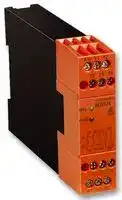
BG 5924.48 AC/DC 24V
Safety Relay, 24 VAC/VDC, 3PST-NO, SPST-NC, BG 5924 Series, DIN Rail, 5 A, Screw
⚠️ Reference pricing provided. In case of supply shortages, we will connect you with our trusted procurement partners to ensure your project's continuity.
- Manufacturer: DOLD
- Product type: Safety Relays
- Coil Voltage:24V; Contact Configuration:3PST-NO, SPST-NC; Product Range:BG 5924 Series; Relay Mounting:DIN Rail; Contact Current:5A; Relay Terminals:Screw; Contact Voltage AC Nom:
- IP Rating: IP20, IP40
- Coil Voltage: 24VAC/VDC
- Product Range: BG 5924 Series
- Relay Mounting: DIN Rail
- Contact Current: 5A
- Relay Terminals: Screw
- Contact Material: -
- Contact Configuration: 3PST-NO, SPST-NC
- Contact Voltage AC Nom: 230V
- Contact Voltage DC Nom: -
| Delivery and price | |
|---|---|
| Units per pack | 1 |
| Price | 225.7 € |
| Current stock | 10+ |
| Lead time | 30 days |
Datasheet

**Safety technique**

**Emergency Stop Module BG 5924, IP 5924 safemaster**

**==> picture [254 x 135] intentionally omitted <==**

**----- Start of picture text -----**<br>
a<br>¥<br>SNa<br>en = \<br>\ 633" ‘ F ioae<br>a Zs ; i 28 * id 4 |<br>a : K2 Leb d<br>eee st) ad<br>BG 5924 IP 5924<br>0225592<br>**----- End of picture text -----**<br>


## According to EU directive for machines 98/37/EG

According to IEC 204-1, DIN EN 60 204-1:1997, DIN VDE 0113-1 Safety category 4 according to DIN EN 954-1

Single channel operation

Output: max. 4 NO contacts

- AC 230 V model with galvanic separation

For thermal currents to 7 A

- LED indicator for channel 1 / 2 and state of operation

- Line fault detection on ON-button, terminal Y1 BG 5924 with:

- a Removable terminal strips Wire connection: also 2 x 1,5 mm[2] stranded ferruled (isolated), DIN 46 228-4 or

- 2 x 2,5 mm[2] stranded ferruled DIN 46 228-1/-2/-3

- BG 5924: width 22,5 mm

IP 5924: width 70 mm

## **Function diagram**

## **Approvals and marking**

**==> picture [160 x 129] intentionally omitted <==**

**----- Start of picture text -----**<br>
Pushbutton<br>On<br>Emergency<br>stop (Off)<br>K1<br>K2<br>M7218<br>**----- End of picture text -----**<br>


**==> picture [229 x 36] intentionally omitted <==**

**----- Start of picture text -----**<br>
1) 2) 2)<br>1) for BG 5924 existing<br>Cc@-US C€ for IP 5924 pending<br>ET Canada / USA Canada / USA 2) for BG 5924<br>**----- End of picture text -----**<br>


## **Applications**

Protection of people and machines

Emergency stop circuits on machines

## **Indicators**

LED Netz: on, when supply connected LED K1/K2: on, when relay K1 and K2 energized

## **Block diagrams**

BG 5924.48, BG 5924.48/207, IP 5924.48

BG 5924.02, BG 5924.02/207, BG 5924.04, BG 5924.04/207, IP 5924.02, IP 5924.04

~~aISssss5s$52984141—M_UIHH|41.,10111HHIHHIHIHIII~~ All technical data in this list relate to the state at the moment of edition. We reserve the right for technical improvements and changes at any time. 1 BG 5924, IP 5924 / 30.10.01 d

1

## **Circuit diagrams**

**==> picture [327 x 277] intentionally omitted <==**

**----- Start of picture text -----**<br>
A1 Y1 Y2<br>13 23 A1 13 23<br>A1 13 23 A1 13 23<br>Y1 K1 Y1 K1<br>Y2 Y2<br>K2 K2<br>A2 14 24 A2 14 24<br>14 24 A2 14 24<br>M7129 M7130<br>A2 Y1 Y2<br>BG 5924.02 BG 5924.02/207<br>43 A1 Y1 Y2<br>A1 13 23 33 13 23 33<br>A1 13 23 33 43 A1 13 23 33 41<br>Y1 Y1<br>K1 K1<br>Y2 Y2<br>K2 K2<br>A2 14 24 34 44 A2 14 24 34 42<br>A2 14 24 34 14 24 34<br>M7131 M7385_a<br>Y1 Y2 44 41 42 A2<br>BG 5924.04/207 BG 5924.48<br>**----- End of picture text -----**<br>


**==> picture [331 x 459] intentionally omitted <==**

**----- Start of picture text -----**<br>
A1 Y1 Y2<br>A1 13 23 13 23 33 43<br>A1 13 23 A1 13 23 33 43<br>Y1 K1 Y1 K1<br>Y2 Y2<br>K2 K2<br>A2 14 24 A2 14 24 34 44<br>A2 14 24 14 24 34 44<br>M7130 M7386_a<br>Y1 Y2 A2<br>BG 5924.02/207 BG 5924.04<br>A1 Y1 Y2 41<br>13 23 33 A1 13 23 33<br>A1 13 23 33 41 A1 13 23 33 41<br>Y1 Y1<br>K1 K1<br>Y2 Y2<br>K2 K2<br>A2 14 24 34 42 A2 14 24 34 42<br>14 24 34 A2 14 24 34<br>M7385_a M7132<br>41 42 A2 Y1 Y2 42<br>BG 5924.48 BG 5924.48/207<br>A1 13 23 33 43 A1 13 23 33 41<br>Y1 K1 Y1 K1<br>Y2 Y2<br>K2 K2<br>A2 14 24 34 44 A2 14 24 34 42<br>A1 Y1 13 23 33 43 A1 Y1 13 23 33 41<br>A2 Y2 14 24 34 44 A2 Y2 14 24 34 42<br>M7912 M7913<br>IP 5924.04 IP 5924.48<br>**----- End of picture text -----**<br>


**==> picture [138 x 174] intentionally omitted <==**

**----- Start of picture text -----**<br>
A1 13 23<br>Y1 K1<br>Y2<br>K2<br>A2 14 24<br>A1 Y1 13 23<br>A2 Y2 14 24<br>M7911<br>IP 5924.02<br>**----- End of picture text -----**<br>


IP 5924.04

## **Technical data**

## **Input**

**Nominal voltage UN:** BG 5924: DC 24 V AC/DC 24 V AC 230 V

AC/DC 24, 48 V AC 110, 230 V AC 0,8 ... 1,1 UN DC 0,9 ... 1,1 UNN DC 0,8 ... 1,1 UNN

## IP 5924:

**Voltage range:**

at 10 % residual ripple: DC 0,9 ... 1,1 UNN at 48 % residual ripple: DC 0,8 ... 1,1 UNN **Nominal consumption** AC/DC 24 V: DC 1,2 W AC 2 VA AC 230 V: 3,5 VA

**Control voltage on Y1** AC/DC 24 V: typ. DC 23 V AC 230 V: max. 45 V short pulse **Control current:** typ. DC 45 mA **Recovery time:** 0,5 s

## **Output**

## **Contacts**

BG 5924.02, IP 5924.02: 2 NO contacts BG 5924.04, IP 5924.04: 4 NO contacts BG 5924.48, IP 5924.48: 3 NO, 1 NC contacts **Operate delay:** max. 100 ms **Release delay:** max. 35 ms **Contact type:** positive guided

**Thermal current Ith:** BG 5924.04/207 terminal 43/44: BG 5924.48, BG 5924.48/207 terminal 41/42:

max. 7 A / 7 A**

max. 5 A

max. 5 A

** device mounted with distance to next device (see total current limit curve) AC 250 V AC 8 A cos � 1 ... 0,7

**Nominal output voltage: Max. switching current: Switching capacity** to AC 15:

3 A / AC 230 V EN 60 947-5-1 for NO contact 2 A / AC 230 V EN 60 947-5-1 for NC contact

## **Electrical life**

10[5] switching cycles EN 60 947-5-1

to AC 15 at 2 A, AC 230 V: **Permissible operating frequency:**

600 switching cycles / h

**Short circuit strength** max. fuse rating: line circuit breaker: **Mechanical life:**

4 A gL EN 60 947-5-1 C 8 A 10 x 10[6] switching cycles

## **General data**

**Operating mode:** Continuous operation **Temperature range:** - 15 ... + 55 � C

2

## **Technical data**

## **Characteristics**

## **Clearance and creepage distances**

overvoltage category / contamination level 4 kV / 2 IEC 60 664-1 **EMC** Electrostatic discharge: 8 kV (air) EN 61 000-4-2 HF irradiation: 10 V / m EN 61 000-4-3 Fast transients: 2 kV EN 61 000-4-4 Surge voltages between wires for power supply: 1 kV EN 61 000-4-5 between wire and ground: 2 kV EN 61 000-4-5 HF wire guided: 10 V EN 61 000-4-6 Interference suppression Limit value class B EN 55011 **Degree of protection:** Housing: IP 40 EN 60 529 Terminals: IP 20 EN 60 529 **Housing:** Thermoplastic with V0 behaviour according to UL subject 94 **Vibration resistance:** Amplitude 0,35 mm frequency 10 ... 55 Hz, EN 60 068-2-6 **Climate resistance:** 15 / 055 / 04 EN 60 068-1 **Terminal designation:** DIN EN 50 005 **Wire connection:** BG 5924: 1 x 4 mm[2] solid or 1 x 2,5 mm[2] stranded ferruled (isolated) or

2 x 1,5 mm[2] stranded ferruled (isolated) DIN 46 228-1/-2/-3/-4 or 2 x 2,5 mm[2] stranded ferruled DIN 46 228-1/-2/-3 IP 5924: 2 x 1,5 mm[2] stranded ferruled or 1 x 2,5 mm[2] stranded ferruled DIN 46 228-1/-2/-3/-4 **Wire fixing:** Box terminal wih wire protection, removable terminal strips **Mounting:** DIN rail EN 50 022 **Weight:** 210 g

## **Dimensions**

**Width x height x depth:** BG 5924: 22,5 x 84 x 121 mm IP 5924: 70 x 90 x 59 mm

## **Standard type**

BG 5924.48  AC/DC 24 V Article number: 0050982 � Output: 3 NO, 1 NC contacts � Nominal voltage UN: AC/DC 24 V � Width: 22,5 mm IP 5924.48 AC/DC 24 V 50/60 Hz Article number: 0053262 � Output: 3 NO, 1 NC contacts � Nominal voltage UN: AC/DC 24 V � Width: 70 mm

## **Variant**

BG 5924._ _/61: UL-approval BG 5924._ _/207: special terminal arrangement, (see circuit diagrams), for AC/DC 24 V or AC 230 V

## **Ordering example for Variant**

|BG|5924<br>.48|5924<br>.48|/|||AC/DC 24V<br>Nominal voltage<br>Variant, if required<br>Contact<br>Type<br>V<br>Nominal voltage<br>Contact<br>Type|AC/DC 24V<br>Nominal voltage<br>Variant, if required<br>Contact<br>Type<br>V<br>Nominal voltage<br>Contact<br>Type|
|---|---|---|---|---|---|---|---|
||||_|_ _||||
|||||||||
|||||||||
|||||||||
|IP 5924<br>.48|||AC 230|||V||
|||||||||
|||||||||
|||||||||
|||||||||


Total current limit curve

## **Application examples**

**==> picture [260 x 316] intentionally omitted <==**

**----- Start of picture text -----**<br>
L1(+)<br>E-Stop ON<br>A1(+) Y1 Y2 13 23 33 41<br>BG5924, IP5924<br>A2(-) 14 24 34 42<br>N(-) M6993_a<br>Single channel emergency-stop circuit without feed back loop,<br>with or without automatic restart.<br>For automatic restart terminals Y1-Y2 must be linked.<br>No ON-pushbutton necessary.<br>L1(+)<br>K3<br>E-stop ON K4<br>A1(+) Y1 Y2 13 23 33 41<br>BG5924, IP5924<br>A2(-) 14 24 34 42<br>K3 K4<br>M6994_a<br>N(-)<br>**----- End of picture text -----**<br>


Contact reinforcement by external contactors, 2-channel controlled. For currents > 7 A the output contacts can be reinforced by external contactors. Functioning of the external contactors is monitored by looping the NC contacts into the start circuit (Y1-Y2).

3

**E. DOLD & SÖHNE KG • D-78114 Furtwangen** • Postf. 1251 • Tel. +49 7723 654 0 • Telefax +49 7723 654 356

e-mail dold-relays@t-online.de • internet http://www.dold.com

4
Updated at April 23, 2026
About Novapart
Novapart is a B2B electronic component broker specialising in stock shortages and cost reduction. We source hard-to-find parts and identify compliant alternatives across a catalogue of 410,000+ components from 500+ manufacturers.
Learn more →Stock Shortage Specialist
When a component is unavailable, discontinued or has an unacceptable lead time, we tap into our network of vetted European and Asian distributors to source what you need — without compromising on quality or traceability.
Request a quote →Compliant Alternatives
We identify pin-to-pin, electrically equivalent substitutes that meet the same certifications (RoHS, AEC-Q100, REACH) as your original specification — validated against datasheets, not just part numbers. Often at a lower cost.
BOM Analysis service →