
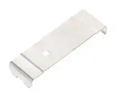


APQ20-2
Circular Aperture, WORLD-BEAM Q20 Series Sensor, 2mm, Set of 2
- Manufacturer: BANNER ENGINEERING
- Product type:
- SVHC: No SVHC (15-Jan-2018)
- For Use With: WORLD-BEAM Q20 Series Photoelectric Sensors
- Accessory Type: Circular Aperture
| Delivery and price | |
|---|---|
| Units per pack | 100 |
| Price | 15.66 € |
| Current stock | 10+ |
| Lead time | 30 days |
## WORLD-BEAM[®] Q20 Series Sensor

## Datasheet

**==> picture [67 x 112] intentionally omitted <==**

- Photoelectric sensors in a compact, rugged, sealed, over-molded plastic housing

- Standard 3 mm threaded mounting holes on 25.4 mm (1 in) spacing

- Advanced electronic design for excellent noise immunity and cross-talk avoidance

- Threaded metal M8 connector on certain quick-disconnect models

- 10 V DC to 30 V DC operation with complementary solid-state outputs (1 normally open, 1 normally closed); PNP or NPN, depending on model

- Complete offering of mounting brackets and apertures available

- Crosstalk prevention filters available for visible red opposed mode pairs

- Exceptional optical performance with easy to align visible red emitters

- Background suppression models provide reliable detection up to 150 mm while ignoring objects in the background

- Background suppression models provide stable detection in the presence of fluorescent lights

## **WARNING:**

- **Do not use this device for personnel protection**

- Using this device for personnel protection could result in serious injury or death.

- This device does not include the self-checking redundant circuitry necessary to allow its use in personnel safety applications. A device failure or malfunction can cause either an energized (on) or deenergized (off) output condition.

## Models

|**Model**<br>1|**Sensing Mode**|**Range**|**Output**<br>2|**Model**<br>1|**Sensing Mode**|**Range**|**Output**<br>2|
|---|---|---|---|---|---|---|---|
|**Q20E**|Opposed, 624 nm Visible<br>Red<br>Effective Beam: 10 mm<br>(0.4 in)|12 m (39.4 ft)|N/A|**Q20PDXL**|Long Range DIffuse, 850<br>nm Infrared|1500 mm (59<br>in)|PNP|
|**Q20PR**|||PNP|**Q20NDXL**|||NPN|
|**Q20NR**|||NPN|**Q20PD**|Short Range Diffuse, 624<br>nm Visible Red|250 mm (10 in)|PNP|
|**Q20EL**|Opposed, 850 nm<br>Infrared<br>Effective Beam: 10 mm<br>(0.4 in)|20 m (65.6 ft)|N/A|**Q20ND**|||NPN|
|**Q20PRL**|||PNP|**Q20PDVS**|Small Spot Diffuse, 660 nm<br>Visible Red|250 mm (10 in)|PNP|
|**Q20NRL**|||NPN|**Q20NDVS**|||NPN|
|||||**Q20PFF50**|Fixed Field, 655 nm Visible<br>Red|50 mm (2 in)<br>cutoff|PNP|
|**Q20PLP**|Polarized Retroreflective,<br>645 nm Visible Red|4 m (13 ft)<br>(specified using<br>reflector BRT-84)|PNP|||||
|||||**Q20NFF50**|||NPN|
|**Q20NLP**|||NPN|||||
|||||**Q20PFF100**||100 mm (4 in)<br>cutoff|PNP|
|**Q20PLV**|Retroreflective, 645 nm<br>Visible Red|6 m (20 ft)<br>(specified using<br>reflector BRT-84)|PNP|||||
|||||**Q20NFF100**|||NPN|
|**Q20NLV**|||NPN|||||
|||||**Q20PFF150**||150 mm (6 in)<br>cutoff|PNP|
|**Q20PDL**|Long-Range Diffuse, 624<br>nm Visible Red|800 mm (32 in)|PNP|**Q20NFF150**|||NPN|
|**Q20NDL**|||NPN|||||


Diffuse-mode and fixed-field performances are based on the use of a 90% reflectance white test card.

- 1 Integral 2 m (6.5 ft) unterminated cable models are listed.

   - To order the 9 m (30 ft) PVC cable model, add the suffix "W/30" to the cabled model number. For example, Q20E W/30.

   - To order the 4-pin M8 integral quick disconnect model, add the suffix "Q7" to the model number. For example, Q20EQ7.

   - To order the 150 mm (6 in) PVC cable model with a 4-pin M8 quick disconnect, add the suffix "Q" to the model number. For example, Q20EQ.

   - To order the 150 mm (6 in) PVC cable model with a 4-pin M12 quick disconnect, add the suffix "Q5" to the model number. For example, Q20EQ5.

   - • To order the 150 mm (6 in) PUR cable model with a 4-pin M12 quick disconnect, add the suffix "QPMA" to the model number. For example, Q20EQPMA.

   - Models with a quick disconnect require a mating cordset.

- 2 Available with Health or Alarm Mode output; contact Banner Engineering for details.

Original Document 127816 Rev. N

6 December 2021

127816

WORLD-BEAM[®] Q20 Series Sensor

## Overview

Banner’s Q20 family of sensors offers a full complement of sensing modes, with the excellent performance expected of much larger sensors. Their compact plastic housings feature overmolded construction for superior robustness and sealing. Their popular rectangular design is easy to mount into tight spaces; integral threaded mounting holes eliminate the need for separate mounting nuts.

The single-turn Gain potentiometer on most models and bright LEDs (positioned on top of the housing for 360° visibility) provide easy alignment and configuration for reliable sensing.

**==> picture [78 x 112] intentionally omitted <==**

**----- Start of picture text -----**<br>
3<br>2<br>1<br>**----- End of picture text -----**<br>


(varies with model)

1. Output LED 2. Power LED

3. Single-Turn Gain Potentiometer (Retro and Diffuse models only)

## Wiring Diagrams

Cabled wiring diagrams are shown. Quick disconnect wiring diagrams are functionally identical.

**==> picture [437 x 88] intentionally omitted <==**

**----- Start of picture text -----**<br>
Emitter PNP Output NPN Output Key<br>1. Brown<br>2. White<br>brown bn (1) +  bu (3) – 3. Blue<br>+ bu (3) 10–30 V dc– bn (1) 10–30 V dc+ 4. Black<br>10–30 V DC bk (4) Loa d bk (4) Load<br>blue<br>– wh (2) wh (2)<br>Load Load<br>**----- End of picture text -----**<br>


**==> picture [194 x 52] intentionally omitted <==**

**----- Start of picture text -----**<br>
4-pin M8 Male QD 4-pin M12 Male QD<br>2 4 1<br>2<br>1 3 4<br>3<br>**----- End of picture text -----**<br>


## Specifications

## **Supply Voltage**

**Fixed-Field:** 10 V DC to 30 V DC (10% maximum ripple within specified limits) at less than 25 mA, exclusive of load

**All others:** 10 V DC to 30 V DC (10% maximum ripple within specified limits) at less than 18 mA, exclusive of load

## **Supply Protection Circuitry**

## **Repeatability**

Opposed mode: 140 microseconds All other models: 90 microseconds

## **Construction**

ABS housing; PMMA lenses; PBT Gain Adjuster (Retro and Diffuse models only)

Protected against reverse polarity and transient voltages

P/N 127816 Rev. N

2

www.bannerengineering.com - Tel: + 1 888 373 6767

WORLD-BEAM[®] Q20 Series Sensor

## **Output Configuration for Receiver**

100 mA with short circuit protection OFF-state leakage current: NPN: < 200 µA sinking (see Application Note 2); PNP: < 10 µA sourcing ON-state saturation voltage NPN: < 1.6 V at 100 mA PNP: < 3.0 V at 100 mA

## **Output Configuration for all Other Models**

Maximum Current ≤ 100 mA PNP Output Voltage:

High ≥ Vsupply – Vsaturation Low ≤ 1 V (≤ 1M Ω) NPN Output Voltage: High ≥ Vsupply – 1 V (≤ 1M Ω) Low ≤ Vsaturation Vsaturation ≤ 3 V

## **Connections**

2 m (6.5 ft) or 9 m (30 ft) 4-wire PVC cable, 150 mm (6 in) cable with 4-pin threaded M8 (Q) or M12 (Q5) connector, or 4-pin integral threaded M8 connector (Q7), depending on the model ordered

## **Indicators**

Two LED Indicators: Power (green) and Output (amber) Fixed-Field models:

Green on: Power ON

Amber on: Black (LO) wire conducting All other models:

Green on: Power ON Amber on: Black (LO) wire conducting Amber flashing: Marginal excess gain (1 to 1.5×) Black (LO) wire conducting

## **Adjustments**

- **Diffuse, Retroreflective, and Polarized Retroreflective models (only):** Single-turn Sensitivity (Gain) adjustment potentiometer

## **Output Response Time**

Opposed mode: 1 millisecond ON/600 microseconds OFF All other models: 850 microseconds ON/OFF 100 millisecond delay on power-up; outputs do not conduct during this time

## **Applications Notes**

1. Opposed mode sensor spacing can be reduced by alternating emitters and receivers or by applying cross talk filters (visible red models only)

2. For receiver only: NPN off-state leakage current is <200 µA for load resistances > 3kΩ or optically isolated loads. For load currents of 100 mA, leakage is <1% of load current.

## **Operating Conditions**

–20 °C to +60 °C (–4 °F to +140 °F) 95% at +50 °C maximum relative humidity (non-condensing)

## **Environmental Rating**

IP67; NEMA 6

## **Vibration and Mechanical Shock**

All models meet MIL-STD-202F, Method 201A (Vibration: 10 Hz to 60 Hz maximum, 0.06 inch (1.52 mm) double amplitude, 10G maximum acceleration) requirements. Also meets IEC 60947-5-2 (Shock: 30G 11 ms duration, half sine wave) requirements.

## **Certifications**

(Class 2 power supply required)

## **Required Overcurrent Protection**

**WARNING:** Electrical connections must be made by qualified personnel in accordance with local and national electrical codes and regulations.

Overcurrent protection is required to be provided by end product application per the supplied table.

Overcurrent protection may be provided with external fusing or via Current Limiting, Class 2 Power Supply.

Supply wiring leads < 24 AWG shall not be spliced.

For additional product support, go to www.bannerengineering.com.

|**Supply Wiring (AWG)**|**Required Overcurrent Protection (Amps)**|
|---|---|
|20|5.0|
|22|3.0|
|24|2.0|
|26|1.0|
|28|0.8|
|30|0.5|


## Performance Curves

**Opposed Mode Models**

**==> picture [500 x 146] intentionally omitted <==**

**----- Start of picture text -----**<br>
Excess Gain Beam Pattern<br>1000 Q20 Opposed Mode<br>E Q20 1200 mm 47"<br>X Opposed 800 mm Infrared 31"<br>C<br>E 100 400 mm 16"<br>SS 0 Filters Visible 0<br>Infrared 400 mm 16"<br>G 10 Filter 800 mm 31"<br>A<br>I Visible 1200 mm 47"<br>N<br>1 0 3 m 6 m 9 m 12 m 15 m 18 m 21 m<br>0.1 m 1.0 m 10 m 100 m 9.8' 19.7' 29.5' 39.4' 49.2' 59.0' 68.9'<br>0.3' 3.0' 30' 300'<br>DISTANCE DISTANCE<br>**----- End of picture text -----**<br>


P/N 127816 Rev. N

www.bannerengineering.com - Tel: + 1 888 373 6767

3

WORLD-BEAM[®] Q20 Series Sensor

## **Retroreflective Mode Models (based on retroreflector BRT-84)**

**==> picture [501 x 634] intentionally omitted <==**

**----- Start of picture text -----**<br>
Excess Gain Beam Pattern Excess Gain Beam Pattern<br>E 100 Retroreflective ModeQ20 LP  150 mm100 mm Retroreflective Mode Q20 LP  6"4" E 100 Retroreflective Mode Q20 LV  200 mm150 mm Retroreflective ModeQ20 LV  8"6"<br>CXE 50 mm0 2"0 CXE 100 mm50 mm 4"2"<br>S 50 mm 2" S 0 0<br>S 10 100 mm 4" S 10 50 mm 2"<br>G 150 mm 6" G 100 mm 4"<br>A 0 1 m 2 m 3 m 4 m 5 m A 150 mm 6"<br>I 3.3' 6.6' 10' 13' 16' I 200 mm 8"<br>N DISTANCE N 0 2 m6.6' 4 m13' 6 m20' 8 m26'<br>1 1 DISTANCE<br>0.01 m 0.1 m 1.0 m 10.0 m 0.01 m 0.1 m 1.0 m 10.0 m<br>0.4" 4.0" 40.0" 400.0" 0.4" 4.0" 40.0" 400.0"<br>DISTANCE DISTANCE<br>Diffuse Mode Models (based on 90% reflectance white test card)<br>Excess Gain Beam Pattern Excess Gain Beam Pattern<br>1000 Q20 30 mm Q20 Diffuse – short range 1.2" 1000 60 mm Q20 Diffuse – long range 2.4"<br>CEXESS 100 Short Range Diffuse 20 mm10 mm10 mm0 0.8"0.4"00.4" CEXESS 100 Long Ran Q20 ge Diffuse  40 mm20 mm20 mm0 Visible Infrared 1.6"0.8"00.8"<br>20 mm 0.8" G 10 Infrared 40 mm 1.6"<br>G 10 30 mm 1.2" AI Visible 60 mm 2.4"<br>A N<br>I 0 50 mm 100 mm 150 mm 200 mm 250 mm 1 0 300 mm 600 mm 900 mm 1200 mm 1500 mm<br>N 2.0" 4.0" 6.0" 8.0" 10" 1.0 mm0.04" 10.0 mm0.4" 100 mm4.0" 1000 mm40.0" 10000 mm400" 12" 24" 35" 47" 59"<br>1 DISTANCE DISTANCE DISTANCE<br>1.0 mm 10.0 mm 100 mm 1000 mm<br>0.04" 0.4" 4.0" 40.0"<br>DISTANCE<br>Q20DVS Models<br>Excess Gain Beam Pattern<br>100<br>4<br>3<br>2<br>1<br>10 0<br>-1<br>-2<br>-3<br>-4<br>1 0 50 100 150 200 250<br>1 10 100 1000<br>Distance (mm) Distance (mm)<br>Fixed-Field Excess Gain (based on 90% reflectance white test card)<br>1000 1000 1000<br>Q20 FF  Q20 FF  Q20 FF<br>E 50 mm E 100 mm E 150 mm<br>X X X<br>C C C<br>E 100 E 100 E 100<br>S S S<br>S S S<br>G 10 G 10 G 10<br>A A A<br>I I I<br>N N N<br>1 1 1<br>1.0 mm 10.0 mm 100 mm 1000 mm 1.0 mm 10.0 mm 100 mm 1000 mm 1.0 mm 10.0 mm 100 mm 1000 mm<br>0.04" 0.4" 4.0" 40.0" 0.04" 0.4" 4.0" 40.0" 0.04" 0.4" 4.0" 40.0"<br>DISTANCE DISTANCE DISTANCE<br>Excess Gain Width (mm)<br>**----- End of picture text -----**<br>


P/N 127816 Rev. N

www.bannerengineering.com - Tel: + 1 888 373 6767

4

WORLD-BEAM[®] Q20 Series Sensor

## **Fixed-Field Excess Gain (based on 90% reflectance white test card)**

|**Fixed-Field Excess Gain (based on 90% reflectance white test card)**|**Fixed-Field Excess Gain (based on 90% reflectance white test card)**|**Fixed-Field Excess Gain (based on 90% reflectance white test card)**|**Fixed-Field Excess Gain (based on 90% reflectance white test card)**|**Fixed-Field Excess Gain (based on 90% reflectance white test card)**|
|---|---|---|---|---|
||Ø 6 mm spot size at 25 mm<br>Ø 6 mm spot size at 50 mm cutoff<br>**Using 18% gray test card:**cutoff distance will<br>be 95% of value shown<br>**Using 6% black test card:**cutoff distance will be<br>90% of value shown|Ø 6 mm spot size at 50 mm<br>Ø 6 mm spot size at 100 mm cutoff<br>**Using 18% gray test card:**cutoff distance will<br>be 90% of value shown<br>**Using 6% black test card:**cutoff distance will<br>be 85% of value shown|Ø 6 mm spot size at 75 mm<br>Ø 9 mm spot size at 150 mm cutoff<br>**Using 18% gray test card:**cutoff distance will<br>be 80% of value shown<br>**Using 6% black test card:**cutoff distance will be<br>70% of value shown||


See Accessories on page 5, the Accessories section of the current Banner catalog, or www.bannerengineering.com for complete information.

**Note:** Polarized sensors require corner cube type retroreflective targets only.

## Dimensions

All measurements are listed in millimeters [inches], unless noted otherwise.

## **Cabled and Pigtail QD Models**

**==> picture [453 x 253] intentionally omitted <==**

**----- Start of picture text -----**<br>
20.0 mm<br>(0.79")<br>3.3 mm  12.0 mm (0.47") Integral QD<br>(0.13") 3.3 mm  1.8 mm  Models<br>(0.07")<br>(0.13")<br>10.5 mm<br>(0.42")<br>25.4 mm  9.9 mm  32.0 mm<br>(1.00") (0.39") (1.26") 42.0 mm<br>(1.65")<br>2X M3 X0.5<br>Max. Torque<br>0.56 Nm (5 in. lbs.)<br>2 - M3 screws (12 mm)<br>washers included<br>**----- End of picture text -----**<br>


## Accessories

## Mounting Brackets

**==> picture [500 x 93] intentionally omitted <==**

**----- Start of picture text -----**<br>
SMBQ20L 16 SMBQ20LV 4 X<br>Ø3.4 15<br>• Sensor vertical base mount • Sensor vertical back mount Ø3.2<br>• ±5° tip, ±7° swivel 4 X  • ±10° tip<br>• Stainless steel Ø3.2 • Stainless steel 2 X  36<br>40 Ø3.2<br>4 X<br>14 Ø3.4 31<br>**----- End of picture text -----**<br>


P/N 127816 Rev. N

www.bannerengineering.com - Tel: + 1 888 373 6767

5

WORLD-BEAM[®] Q20 Series Sensor

## **SMBQ20H**

- Sensor horizontal flange mount

- • ±10° swivel

- Stainless steel

**==> picture [314 x 65] intentionally omitted <==**

**----- Start of picture text -----**<br>
Pag 16 23 SMBQ20U • Sensor vertical base mount with 4 X  23 s!<br>protection Ø3.2 39<br>4 X  • ±22.5° swivel<br>Ø3.2 55<br>• Stainless steel<br>Ø3.44 X  34 12.5 Ø3.24 X<br>**----- End of picture text -----**<br>


## Cross Talk Prevention Filters

|**Model**<br>3|**Description**|**Description**|**Description**|**Reduced Sensor Range E/R (two**<br>**apertures used)**|
|---|---|---|---|---|
|PFQ20-H||Stainless steel (natural color)<br>7.5 mm (0.3 in) dia.<br>Stainless steel (colorized black)|7.5 mm (0.3 in) dia.|6.0 m (19.7 ft)|
|PFQ20-V|||||


Quick-Disconnect (QD) Cordsets

**==> picture [500 x 185] intentionally omitted <==**

**----- Start of picture text -----**<br>
4-Pin Threaded M12 Cordsets—Single Ended<br>a<br>Model Length Style Dimensions Pinout (Female)<br>a a ee es<br>MQDC-406 2 m (6.56 ft)<br>44 Typ.<br>MQDC-415 5 m (16.4 ft) 2<br>1<br>MQDC-430 9 m (29.5 ft) Straight 3<br>M12 x 1 4 5<br>MQDC-450 15 m (49.2 ft) ø 14.5<br>1 = Brown<br>MQDC-406RA 2 m (6.56 ft) 2 = White<br>32 Typ. 3 = Blue<br>MQDC-415RA 5 m (16.4 ft) [1.26"] 2 4 = Black<br>3 5 = Unused<br>MQDC-430RA 9 m (29.5 ft)<br>30 Typ. 1<br>Right-Angle ( aa [1.18"] (@) 4<br>MQDC-450RA 15 m (49.2 ft) M12 x 1<br>ø 14.5 [0.57"]<br>**----- End of picture text -----**<br>


**==> picture [500 x 194] intentionally omitted <==**

**----- Start of picture text -----**<br>
4-Pin Snap-on M8 Cordsets—Single Ended<br>a<br>Model Length Style Dimensions Pinout (Female)<br>a a ee ee<br>32 Typ.<br>4 2<br>PKG4-2 2.03 m (6.66 ft) Straight a<br>ø 9.0 3 1<br>C T<br>——+<br>1 = Brown<br>4 2 2 = White<br>29 Typ. 3 = Blue<br>4 = Black<br>3 1<br>PKW4Z-2 2 m (6.56 ft) Right-Angle 15 Typ.<br>——i- IIs =<br>ø 10.9<br>am =<br>**----- End of picture text -----**<br>


- 3 For visible red models only. The "H" and "V" in the model numbers refer to the polarization of the filter material. Since they are visually identical, the "H" models have been left the natural stainless steel and the "V" models have been colored black.

P/N 127816 Rev. N

6

www.bannerengineering.com - Tel: + 1 888 373 6767

WORLD-BEAM[®] Q20 Series Sensor

**4-Pin Threaded M8 Cordsets—Single Ended** ~~a~~

|**4-Pin Threaded M8 Cordsets—Single Ended**<br>~~a~~|**4-Pin Threaded M8 Cordsets—Single Ended**<br>~~a~~|**4-Pin Threaded M8 Cordsets—Single Ended**<br>~~a~~|**4-Pin Threaded M8 Cordsets—Single Ended**<br>~~a~~|**4-Pin Threaded M8 Cordsets—Single Ended**<br>~~a~~|**4-Pin Threaded M8 Cordsets—Single Ended**<br>~~a~~|
|---|---|---|---|---|---|
|**Model**<br>~~pO~~|**Length**<br>~~pO~~|**Style**<br>~~pO~~|**Dimensions**<br>~~pO~~|**Pinout (Female)**<br>~~pO~~||
|**PKG4M-2**<br>~~pO~~|2.04 m (6.68 ft)<br>~~pO~~|Straight<br>~~pO~~|**ø 9.5**<br>**35 Typ.**<br>**M8 x 1**<br>~~pO~~<br>~~at~~|**4**<br>**3**<br>**1**<br>**2**<br>~~pO~~<br>oS|1 = Brown<br>2 = White<br>3 = Blue<br>4 = Black<br>~~pO~~|
|**PKG4M-5**|5 m (16.4 ft)|||||
|**PKG4M-9**|9.04 m (29.6 ft)|||||
|**PKW4M-2**|2 m (6.56 ft)|Right Angle|**ø 9.5**<br>**28 Typ.**<br>**20 Typ.**<br>**M8 x 1**<br>~~=~~<br>~~= |~~<br>~~c~~i~~a~~|**1**<br>**2**<br>**3**<br>**4**<br>~~=~~||
|**PKW4M-5**|5 m (16.4 ft)|||||
|**PKW4M-9**|9 m (29.5 ft)|||||


## Apertures

|**Model**||**Reduced Sensor Range**|**Reduced Sensor Range**|**Description**|**Description**|**Description**|
|---|---|---|---|---|---|---|
|||**E/R (two apertures**|**EL/RL (two apertures**||||
|||**used)**|**used)**||||
|||**Circular**|||||
||||||||
|**APQ20-0.5**|0.5 mm (0.02") dia.|0.10 m (0.33 ft)|0.18 m (0.6 ft)||||
|**APQ20-1**|1 mm (0.04") dia.|0.35 m (1.14 ft)|0.66 m (2.1 ft)||||
|**APQ20-2**|2 mm (0.08") dia.|1.5 m (4.9 ft)|2.9 m (9.5 ft)||||
||**Vertical Slot**||||||
|**APQ20-0.5V**|0.5 mm (0.02") dia.|1.4 m (4.6 ft)|2.3 m (7.5 ft)||||
|**APQ20-1V**|1 mm (0.04") dia.|2.8 m (9.2 ft)|4.8 m (15.7 ft)||||
|**APQ20-2V**|2 mm (0.08") dia.|5.8 m (19.0 ft)|8.6 m (28.2 ft)||||
|**APK-Q20**|Includes two of each type||||||


## Banner Engineering Corp. Limited Warranty

Banner Engineering Corp. warrants its products to be free from defects in material and workmanship for one year following the date of shipment. Banner Engineering Corp. will repair or replace, free of charge, any product of its manufacture which, at the time it is returned to the factory, is found to have been defective during the warranty period. This warranty does not cover damage or liability for misuse, abuse, or the improper application or installation of the Banner product.

**THIS LIMITED WARRANTY IS EXCLUSIVE AND IN LIEU OF ALL OTHER WARRANTIES WHETHER EXPRESS OR IMPLIED (INCLUDING, WITHOUT LIMITATION, ANY WARRANTY OF MERCHANTABILITY OR FITNESS FOR A PARTICULAR PURPOSE), AND WHETHER ARISING UNDER COURSE OF PERFORMANCE, COURSE OF DEALING OR TRADE USAGE.**

This Warranty is exclusive and limited to repair or, at the discretion of Banner Engineering Corp., replacement. **IN NO EVENT SHALL BANNER ENGINEERING CORP. BE LIABLE TO BUYER OR ANY OTHER PERSON OR ENTITY FOR ANY EXTRA COSTS, EXPENSES, LOSSES, LOSS OF PROFITS, OR ANY INCIDENTAL, CONSEQUENTIAL OR SPECIAL DAMAGES RESULTING FROM ANY PRODUCT DEFECT OR FROM THE USE OR INABILITY TO USE THE PRODUCT, WHETHER ARISING IN CONTRACT OR WARRANTY, STATUTE, TORT, STRICT LIABILITY, NEGLIGENCE, OR OTHERWISE.**

Banner Engineering Corp. reserves the right to change, modify or improve the design of the product without assuming any obligations or liabilities relating to any product previously manufactured by Banner Engineering Corp. Any misuse, abuse, or improper application or installation of this product or use of the product for personal protection applications when the product is identified as not intended for such purposes will void the product warranty. Any modifications to this product without prior express approval by Banner Engineering Corp will void the product warranties. All specifications published in this document are subject to change; Banner reserves the right to modify product specifications or update documentation at any time. Specifications and product information in English supersede that which is provided in any other language. For the most recent version of any documentation, refer to: www.bannerengineering.com.

For patent information, see www.bannerengineering.com/patents.

P/N 127816 Rev. N

www.bannerengineering.com - Tel: + 1 888 373 6767

7

WORLD-BEAM[®] Q20 Series Sensor

## FCC Part 15 and CAN ICES-3 (B)/NMB-3(B)

This device complies with part 15 of the FCC Rules and CAN ICES-3 (B)/NMB-3(B). Operation is subject to the following two conditions: 1) This device may not cause harmful interference; and 2) This device must accept any interference received, including interference that may cause undesired operation.

This equipment has been tested and found to comply with the limits for a Class B digital device, pursuant to part 15 of the FCC Rules and CAN ICES-3 (B)/NMB-3(B). These limits are designed to provide reasonable protection against harmful interference in a residential installation. This equipment generates, uses and can radiate radio frequency energy and, if not installed and used in accordance with the instructions, may cause harmful interference to radio communications. However, there is no guarantee that interference will not occur in a particular installation. If this equipment does cause harmful interference to radio or television reception, which can be determined by turning the equipment off and on, the user is encouraged to try to correct the interference by one or more of the following measures:

- Reorient or relocate the receiving antenna.

- Increase the separation between the equipment and receiver.

- Connect the equipment into an outlet on a circuit different from that to which the receiver is connected.

- Consult the manufacturer.

© Banner Engineering Corp. All rights reserved
Updated at June 9, 2026
Founded in 1966, Banner Engineering is a globally recognized leader in the design and manufacture of industrial automation products. The company is renowned for developing innovative, high-quality solutions that improve operational efficiency, safeguard personnel, and optimize manufacturing processes across a diverse range of industries. Our extensive selection of Banner Engineering components prominently features their industry-leading sensing technologies. We offer a comprehensive array of precision light sensors engineered for accurate detection and measurement in demanding environments. Complementing this core sensing portfolio is a robust offering of automation signaling devices, including visual signal indicator units and essential accessories, which provide clear and immediate communication of machine status. Beyond primary sensing and indication solutions, our range encompasses critical components for broader process control and machine safety. This includes advanced process controllers, reliable pressure sensors and transducers, and dependable safety relays. Supported by a variety of purpose-built sensor accessories and fiber optic lead assemblies, Banner Engineering delivers the durable, high-performance technologies required to build and maintain sophisticated automated systems.
About Novapart
Novapart is a B2B electronic component broker specialising in stock shortages and cost reduction. We source hard-to-find parts and identify compliant alternatives across a catalogue of 410,000+ components from 500+ manufacturers.
Learn more →Stock Shortage Specialist
When a component is unavailable, discontinued or has an unacceptable lead time, we tap into our network of vetted European and Asian distributors to source what you need — without compromising on quality or traceability.
Request a quote →Compliant Alternatives
We identify pin-to-pin, electrically equivalent substitutes that meet the same certifications (RoHS, AEC-Q100, REACH) as your original specification — validated against datasheets, not just part numbers. Often at a lower cost.
BOM Analysis service →