
Image not available
Illustrative purposes only

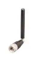
ANT-LTE-MON-SMA-L
RF Antenna, 2.4 to 2.485GHz, Bluetooth/Sigfox/LTE-M/LoRaWAN/UMTS/GSM/ISM/NB-IoT/ZigBee, 3.2dBi
⚠️ Reference pricing provided. In case of supply shortages, we will connect you with our trusted procurement partners to ensure your project's continuity.
- Manufacturer: TE CONNECTIVITY - LINX
- Product type:
- Gain: 3.2dBi
- SVHC: Lead (25-Jun-2025)
- VSWR: 2.1
- Input Power: 10W
- Antenna Type: Bluetooth / Sigfox / LTE-M / LoRaWAN / UMTS / GSM / ISM / NB-IoT / ZigBee
- Frequency Max: 2.485GHz
- Frequency Min: 2.4GHz
- Product Range: -
- Input Impedance: 50ohm
- Antenna Mounting: SMA Connector
- Antenna Polarisation: Linear
| Delivery and price | |
|---|---|
| Units per pack | 1000 |
| Price | 11.35 € |
| Current stock | 10+ |
| Lead time | 30 days |
Datasheet

## **ANT-LTE-MON-SMA-L**

## **Enhanced Low-Band LTE Connectorized Monopole Whip Antenna**

The MON-L antenna is a member of Linx’s LTE-MON family of compact rotatable hinged-whip antennas which offer optimized support for a wide range of cellular LTE and IoT applications.

The MON-L antenna provides excellent multiband cellular and cellular IoT performance. It offers better VSWR at the lower LTE frequency bands, including LTE Band 71 (617 MHz to 698 MHz), on a smaller ground plane than competitive products. This equates to better range in a smaller product design.

The hinged design allows for the antenna to be positioned for optimum performance and reduces the potential for damage from impact compared to a fixed whip design.

## **FEATURES**

- Enhanced low-band coverage (LTE B71) – Efficiency: 73%

- – VSWR: ≤ 3.3 – Peak Gain: 3.4 dBi

- • Covers all common LTE/4G/3G/2G bands • Hinged for optimum positioning • Small, unobtrusive profile, 78.7 mm long

- Extended temperature range to 130 °C

- SMA plug (male pin)

## **APPLICATIONS**

- Cellular IoT: LTE-M (Cat-M1) and NB-IoT – T-Mobile: band 71 – AT&T: bands 12, 14, 17

- – Verizon: band 13 – Europe: bands 8, 20

- – Latin America: bands 5, 28

- – Asia Pacific: bands 5, 8, 20, 28

- • Worldwide LTE, UMTS and GSM • Low-power, wide-area (LPWA) applications

- LoRaWAN®

- – Sigfox®

- • Citizens Broadband Radio Service (CBRS)

- ISM: Bluetooth® and ZigBee®

- FirstNet® Public Safety

- Internet of Things (IoT) devices

- Gateways

## **ORDERING INFORMATION**

Part Number Description ANT-LTE-MON-SMA-L Antenna with SMA plug (male pin)

Available from Linx Technologies and select distributors and representatives.

DATA AND DEVICES / ANT-LTE-MON-SMA-L

## **ELECTRICAL SPECIFICATIONS**

**==> picture [526 x 199] intentionally omitted <==**

**----- Start of picture text -----**<br>
Select Bands Frequency Range VSWR (max.) Peak Gain (dBi) Avg. Gain (dBi) Efficiency (%)<br>LTE 71 617 MHz to 698 MHz 3.3 3.4 -1.5 73<br>LTE 12, 13, 14, 17, 26, 28, 29 698 MHz to 803 MHz 2.2 4.8 -0.7 90<br>LTE 5, 8, 20 791 MHz to 960 MHz 2.6 5.0 -1.1 90<br>LTE 1, 2, 3, 4, 25, 66 1710 MHz to 2200 MHz 3.2 3.9 -1.6 72<br>LTE 30, 40 2300 MHz to 2400 MHz 2.3 3.4 -1.2 77<br>LTE 7, 41 2496 MHz to 2690 MHz 1.9 4.1 -1.1 79<br>LTE 22, 42, 52, 43, 48, 49 3300 MHz to 3800 MHz 2.2 4.6 -2.4 64<br>ISM 2400 MHz to 2485 MHz 2.1 3.2 -1.4 74<br>Polarization Linear Impedance 50 Ω<br>Radiation Omnidirectional Connection SMA Plug (male pin)<br>Max Power 10 W Weight 10.0 g (0.35 oz)<br>Wavelength 1/4-wave Dimensions 78.7 mm (3.1 in)<br>Electrical Type Monopole Operating Temperature -40 °C to +130 °C<br>**----- End of picture text -----**<br>


Electrical specifications and plots measured with a 102 mm x 102 mm (4.0 in x 4.0 in) reference ground plane, edge straight orientation.

## **PRODUCT DIMENSIONS**

Figure 1 provides dimensions of the MON-L. The antenna whip can be tilted 180 degrees, and has detents every 45 degrees enabling the antenna to be oriented in any direction. The rotating base allows for continuous positioning through 360 degrees even while installed.

**==> picture [345 x 209] intentionally omitted <==**

**----- Start of picture text -----**<br>
Ø8.0 mm<br>(0.31 in)<br>78.7 mm<br>(3.10 in)<br>65.0 mm<br>(2.60 in)<br>33.3 mm<br>29.0 mm 49.7 mm<br>(0.76 in)<br>(1.14 in) (2.01 in)<br>Ø10.0 mm<br>(0.40 in)<br>**----- End of picture text -----**<br>


Figure 1: ANT-LTE-MON-SMA-L Antenna Dimensions

DATA AND DEVICES / ANT-LTE-MON-SMA-L

2

## **GROUND PLANE**

1/4-Wave monopole antennas require an associated ground plane counterpoise for proper operation. The size and location of the ground plane relative to the antenna will affect the overall performance of the antenna in the final design. When used in conjunction with a ground plane smaller than that used to tune the antenna, the center frequency typically will shift higher in frequency and the bandwidth will decrease. The proximity of other circuit elements and packaging near the antenna will also affect the final performance.

For further discussion and guidance on the importance of the ground plane counterpoise, please refer to Linx Application Note, _AN-00501: Understanding Antenna Specifications and Operation._

**==> picture [391 x 9] intentionally omitted <==**

**----- Start of picture text -----**<br>
On edge of ground plane, straight On edge of ground plane, bent 90 degrees<br>**----- End of picture text -----**<br>


Figure 2. ANT-LTE-MON-SMA-L on Evaluation PCB

DATA AND DEVICES / ANT-LTE-MON-SMA-L

3

## **EDGE OF GROUND PLANE, STRAIGHT**

The charts on the following pages represent data taken with the antenna oriented at the edge of the ground plane, straight (Edge-Straight), as shown in Figure 3.

Figure 3. ANT-LTE-MON-SMA-L on Edge of Ground Plane, Straight (Edge-Straight)

## **VSWR**

Figure 4 provides the voltage standing wave ratio (VSWR) across the antenna bandwidth. VSWR describes the power reflected from the antenna back to the radio. A lower VSWR value indicates better antenna performance at a given frequency. Reflected power is also shown on the right-side vertical axis as a gauge of the percentage of transmitter power reflected back from the antenna.

**==> picture [459 x 228] intentionally omitted <==**

**----- Start of picture text -----**<br>
5<br>40<br>| ao<br>4<br>30<br>a =o<br>3<br>20<br>a<br>2<br>|He 10<br>1 0<br>600 800 1000 1200 1400 1600 1800 2000 2200 2400 2600 2800 3000 3200 3400 3600 3800<br>Frequency (MHz)<br>617 698 803 960 1710 2200 2300 2400 2496 2690 3300 3800<br>VSWR<br>Reflected Power (%)<br>**----- End of picture text -----**<br>


Figure 4. MON-L VSWR, Edge-Straight, with Frequency Band Highlights

DATA AND DEVICES / ANT-LTE-MON-SMA-L

4

## **RETURN LOSS**

Return loss (Figure 5), represents the loss in power at the antenna due to reflected signals. Like VSWR, a lower return loss value indicates better antenna performance at a given frequency.

**==> picture [464 x 233] intentionally omitted <==**

**----- Start of picture text -----**<br>
0<br>-2<br>-4<br>-6<br>-8<br>-10<br>-12<br>-14<br>-16<br>-18<br>-20<br>600 800 1000 1200 1400 1600 1800 2000 2200 2400 2600 2800 3000 3200 3400 3600 3800<br>Frequency (MHz)<br>617 698 803 960 1710 2200 2300 2400 2496 2690 3300 3800<br>Return Loss (dB)<br>**----- End of picture text -----**<br>


Figure 5. MON-L Return Loss, Edge-Straight, with Frequency Band Highlights

## **PEAK GAIN**

The peak gain across the antenna bandwidth is shown in Figure 6. Peak gain represents the maximum antenna input power concentration across 3-dimensional space, and therefore peak performance at a given frequency, but does not consider any directionality in the gain pattern.

**==> picture [462 x 231] intentionally omitted <==**

**----- Start of picture text -----**<br>
5<br>0<br>-5<br>-10<br>-15<br>-20<br>600 800 1000 1200 1400 1600 1800 2000 2200 2400 2600 2800 3000 3200 3400 3600 3800<br>Frequency (MHz)<br>617 698 803 960 1710 2200 2300 2400 2496 2690 3300 3800<br>Peak Gain (dBi)<br>**----- End of picture text -----**<br>


Figure 6. MON-L Peak Gain, Edge-Straight, with Frequency Band Highlights

DATA AND DEVICES / ANT-LTE-MON-SMA-L

5

## **AVERAGE GAIN**

Average gain (Figure 7), is the average of all antenna gain in 3-dimensional space at each frequency, providing an indication of overall performance without expressing antenna directionality.

**==> picture [462 x 233] intentionally omitted <==**

**----- Start of picture text -----**<br>
5<br>0<br>-5<br>-10<br>-15<br>-20<br>600 800 1000 1200 1400 1600 1800 2000 2200 2400 2600 2800 3000 3200 3400 3600 3800<br>Frequency (MHz)<br>617 698 803 960 1710 2200 2300 2400 2496 2690 3300 3800<br>Average Gain (dBi)<br>**----- End of picture text -----**<br>


Figure 7. MON-L Antenna Average Gain, Edge-Straight, with Frequency Band Highlights

## **RADIATION EFFICIENCY**

Radiation efficiency (Figure 8), shows the ratio of power delivered to the antenna relative to the power radiated at the antenna, expressed as a percentage, where a higher percentage indicates better performance at a given frequency.

**==> picture [464 x 231] intentionally omitted <==**

**----- Start of picture text -----**<br>
100<br>90<br>80<br>70<br>60<br>50<br>40<br>30<br>20<br>10<br>0<br>600 800 1000 1200 1400 1600 1800 2000 2200 2400 2600 2800 3000 3200 3400 3600 3800<br>Frequency (MHz)<br>617 698 803 960 1710 2200 2300 2400 2496 2690 3300 3800<br>Efficiency (%)<br>**----- End of picture text -----**<br>


Figure 8. MON-L Antenna Radiation Efficiency, Edge-Straight, with Frequency Band Highlights

DATA AND DEVICES / ANT-LTE-MON-SMA-L

6

## **RADIATION PATTERNS**

Radiation patterns provide information about the directionality and 3-dimensional gain performance of the antenna by plotting gain at specific frequencies in three orthogonal planes. Antenna radiation patterns for an edge straight orientation are shown in Figure 9 using polar plots covering 360 degrees. The antenna graphic at the top of the page provides reference to the plane of the column of plots below it. Note: when viewed with typical PDF viewing software, zooming into radiation patterns is possible to reveal fine detail.

## **RADIATION PATTERNS - EDGE OF GROUND PLANE, STRAIGHT**

**==> picture [45 x 5] intentionally omitted <==**

**----- Start of picture text -----**<br>
XZ-Plane Gain<br>**----- End of picture text -----**<br>


**==> picture [45 x 5] intentionally omitted <==**

**----- Start of picture text -----**<br>
YZ-Plane Gain<br>**----- End of picture text -----**<br>


XY-Plane Gain

## **610 MHz TO 700 MHz (660 MHz)**

**==> picture [463 x 166] intentionally omitted <==**

**----- Start of picture text -----**<br>
1 1 1<br>35 36 5 2 3 35 36 5 2 3 35 36 5 2 3<br>34 0 4 34 0 4 34 0 4<br>33 -5 5 33 -5 5 33 -5 5<br>-10 -10 -10<br>32 -15 6 32 -15 6 32 -15 6<br>31 -20 7 31 -20 7 31 -20 7<br>-25 -25 -25<br>30 -30 8 30 -30 8 30 -30 8<br>-35 -35 -35<br>29 -40 9 29 -40 9 29 -40 9<br>-45 -45 -45<br>28 -50 10 28 -50 10 28 -50 10<br>27 11 27 nn ees EP} ah | jj 11 27 | tt] WIZE AEE | | 11<br>NY Li DoE OL ee [|]<br>26 12 26 12 26 12<br>25 13 25 13 25 13<br>24 14 24 14 24 14<br>23 15 23 15 23 15<br>22 16 22 16 22 16 610 MHz<br>21 20 18 17 21 20 18 17 21 20 18 17 660 MHz<br>19 19 19 700 MHz<br>XZ-Plane Gain  YZ-Plane Gain  XY-Plane Gain<br>**----- End of picture text -----**<br>


## **700 MHz TO 800 MHz (750 MHz)**

**==> picture [463 x 159] intentionally omitted <==**

**----- Start of picture text -----**<br>
1 1 1<br>35 36 5 2 3 35 36 5 2 3 35 36 5 2 3<br>34 0 4 34 0 4 34 0 4<br>33 -5 5 33 -5 5 33 -5 5<br>-10 -10 -10<br>32 -15 6 32 -15 6 32 -15 6<br>31 -20 7 31 -20 7 31 -20 7<br>f.WeXXSLT -25 SKS \ Ta,seTINS -25  YON 4GEP= -25 — ISS<br>30 -30 8 30 -30 8 30 -30 8<br>-35 -35 -35<br>29 -40 9 29 -40 9 29 -40 9<br>-45 -45 -45<br>28 -50 10 28 -50 10 28 -50 10<br>27 11 27 11 27 11<br>26 12 26 12 26 12<br>25 13 25 13 25 13<br>24 14 24 14 24 14<br>23 15 23 15 23 15<br>22 16 22 16 22 16 690 MHz<br>21 20 18 17 21 20 18 17 21 20 18 17 750 MHz<br>19 19 19 800 MHz<br>XZ-Plane Gain  YZ-Plane Gain  XY-Plane Gain<br>**----- End of picture text -----**<br>


DATA AND DEVICES / ANT-LTE-MON-SMA-L

7

## **RADIATION PATTERNS - EDGE OF GROUND PLANE, STRAIGHT**

## **790 MHz TO 960 MHz (870 MHz)**

**==> picture [471 x 168] intentionally omitted <==**

**----- Start of picture text -----**<br>
1 1 1<br>35 36 5 2 3 35 36 5 2 3 35 36 5 2 3<br>34 0 4 34 0 4 34 0 4<br>33 -5 5 33 -5 5 33 -5 5<br>-10 -10 -10<br>32 -15 6 32 -15 6 32 -15 6<br>31 -20 7 31 -20 7 31 -20 7<br>-25 -25 -25<br>30 -30 8 30 -30 8 30 -30 8<br>-35 -35 -35<br>29 -40 9 29 -40 9 29 -40 9<br>-45 -45 -45<br>28 -50 10 28 -50 10 28 -50 10<br>27 11 27 11 27 11<br>26 12 26 12 26 12<br>25 13 25 13 25 13<br>24 14 24 14 24 14<br>23 15 23 15 23 15<br>22 16 22 16 22 16 790 MHz<br>21 20 18 17 21 20 18 17 21 20 18 17 870 MHz<br>19 19 19 960 MHz<br>XZ-Plane Gain  YZ-Plane Gain  XY-Plane Gain<br>**----- End of picture text -----**<br>


## **1710 MHz TO 2200 MHz (1940 MHz)**

**==> picture [471 x 175] intentionally omitted <==**

**----- Start of picture text -----**<br>
1 1 1<br>35 36 5 2 3 35 36 5 2 3 35 36 5 2 3<br>34 0 4 34 0 4 34 0 4<br>33 -5 5 33 -5 5 33 -5 5<br>-10 -10 -10<br>32 -15 6 32 -15 6 32 -15 6<br>31 -20 7 31 -20 7 31 -20 7<br>-25 -25 -25<br>30 -30 8 30 -30 8 30 -30 8<br>-35 -35 -35<br>29 -40 9 29 -40 9 29 -40 9<br>-45 -45 -45<br>28 -50 10 28 -50 10 28 -50 10<br>27 11 27 11 27 11<br>26 12 26 12 26 12<br>25 13 25 13 25 13<br>24 14 24 14 24 14<br>23 15 23 15 23 15<br>22 16 22 16 22 16 1710 MHz<br>21 20 18 17 21 20 18 17 21 20 18 17 1940 MHz<br>19 19 19 2170 MHz<br>XZ-Plane Gain  YZ-Plane Gain  XY-Plane Gain<br>**----- End of picture text -----**<br>


## **2300 MHz TO 2400 MHz (2350 MHz)**

**==> picture [471 x 173] intentionally omitted <==**

**----- Start of picture text -----**<br>
35 36 5 1 2 3 35 36 5 1 2 3 35 36 5 1 2 3<br>34 0 4 34 0 4 34 0 4<br>33 -5 5 33 -5 5 33 -5 5<br>32 -10-15 6 32 -10-15 6 32 -10-15 6<br>31 -20 7 31 -20 7 31 -20 7<br>-25 -25 -25<br>30 -30 8 30 -30 8 30 -30 8<br>-35 -35 -35<br>29 -40 9 29 -40 9 29 -40 9<br>-45 -45 -45<br>28 -50 10 28 -50 10 28 -50 10<br>27 11 27 11 27 11<br>26 12 26 12 26 12<br>25 13 25 13 25 13<br>24 14 24 14 24 14<br>23 15 23 15 23 15<br>22 16 22 16 22 16 790 MHz<br>21 20 19 18 17 21 20 19 18 17 21 20 19 18 17 870 MHz960 MHz<br>XZ-Plane Gain  YZ-Plane Gain  XY-Plane Gain<br>**----- End of picture text -----**<br>


DATA AND DEVICES / ANT-LTE-MON-SMA-L

8

## **RADIATION PATTERNS - EDGE OF GROUND PLANE, STRAIGHT**

## **2496 MHz TO 2690 MHz (2450 MHz)**

**==> picture [471 x 168] intentionally omitted <==**

**----- Start of picture text -----**<br>
1 1 1<br>35 36 5 2 3 35 36 5 2 3 35 36 5 2 3<br>34 0 4 34 0 4 34 0 4<br>33 -5 5 33 -5 5 33 -5 5<br>-10 -10 -10<br>32 -15 6 32 -15 6 32 -15 6<br>31 -20 7 31 -20 7 31 -20 7<br>-25 -25 -25<br>30 -30 8 30 -30 8 30 -30 8<br>-35 -35 -35<br>29 -40 9 29 -40 9 29 -40 9<br>-45 -45 -45<br>28 -50 10 28 -50 10 28 -50 10<br>27 11 27 11 27 11<br>26 12 26 12 26 12<br>25 13 25 13 25 13<br>24 14 24 14 24 14<br>23 15 23 15 23 15<br>22 16 22 16 22 16 2500 MHz<br>21 20 18 17 21 20 18 17 21 20 18 17 2600 MHz<br>19 19 19 2700 MHz<br>XZ-Plane Gain  YZ-Plane Gain  XY-Plane Gain<br>**----- End of picture text -----**<br>


## **3300 MHz TO 3800 MHz (3550 MHz)**

**==> picture [471 x 175] intentionally omitted <==**

**----- Start of picture text -----**<br>
1 1 1<br>35 36 5 2 3 35 36 5 2 3 35 36 5 2 3<br>34 0 4 34 0 4 34 0 4<br>33 -5 5 33 -5 5 33 -5 5<br>-10 -10 -10<br>32 -15 6 32 -15 6 32 -15 6<br>31 -20 7 31 -20 7 31 -20 7<br>-25 -25 -25<br>30 -30 8 30 -30 8 30 -30 8<br>-35 -35 -35<br>29 -40 9 29 -40 9 29 -40 9<br>-45 -45 -45<br>28 -50 10 28 -50 10 28 -50 10<br>27 11 27 11 27 11<br>26 12 26 12 26 12<br>25 13 25 13 25 13<br>24 14 24 14 24 14<br>23 15 23 15 23 15<br>22 16 22 16 22 16 3300 MHz<br>21 20 18 17 21 20 18 17 21 20 18 17 3550 MHz<br>19 19 19 3800 MHz<br>XZ-Plane Gain  YZ-Plane Gain  XY-Plane Gain<br>**----- End of picture text -----**<br>


## **2400 MHz TO 2500 MHz (2450 MHz)**

**==> picture [471 x 173] intentionally omitted <==**

**----- Start of picture text -----**<br>
1 1 1<br>35 36 5 2 3 35 36 5 2 3 35 36 5 2 3<br>34 0 4 34 0 4 34 0 4<br>33 -5 5 33 -5 5 33 -5 5<br>-10 -10 -10<br>32 -15 6 32 -15 6 32 -15 6<br>31 -20 7 31 -20 7 31 -20 7<br>-25 -25 -25<br>30 -30 8 30 -30 8 30 -30 8<br>-35 -35 -35<br>29 -40 9 29 -40 9 29 -40 9<br>-45 -45 -45<br>28 -50 10 28 -50 10 28 -50 10<br>27 11 27 11 27 11<br>26 12 26 12 26 12<br>25 13 25 13 25 13<br>24 14 24 14 24 14<br>23 15 23 15 23 15<br>22 16 22 16 22 16 2400 MHz<br>21 20 18 17 21 20 18 17 21 20 18 17 2450 MHz<br>19 19 19 2500 MHz<br>XZ-Plane Gain  YZ-Plane Gain  XY-Plane Gain<br>**----- End of picture text -----**<br>


DATA AND DEVICES / ANT-LTE-MON-SMA-L

9

## **EDGE OF GROUND PLANE, BENT 90 DEGREES**

The charts on the following pages represent data taken with the antenna oriented at the edge of the ground plane, bent 90 degrees (Edge-Bent), as shown in Figure 10.

Figure 10. ANT-LTE-MON-SMA-L on Edge of Ground Plane, Bent 90 Degrees (Edge-Bent)

## **VSWR**

Figure 11 provides the voltage standing wave ratio (VSWR) across the antenna bandwidth. VSWR describes the power reflected from the antenna back to the radio. A lower VSWR value indicates better antenna performance at a given frequency. Reflected power is also shown on the right-side vertical axis as a gauge of the percentage of transmitter power reflected back from the antenna.

**==> picture [459 x 228] intentionally omitted <==**

**----- Start of picture text -----**<br>
5<br>40<br>| (a<br>4 =o<br>30<br>3<br>le 20<br>2<br>10<br>a A]<br>Nee<br>1 0<br>600 800 1000 1200 1400 1600 1800 2000 2200 2400 2600 2800 3000 3200 3400 3600 3800<br>Frequency (MHz)<br>617 698 803 960 1710 2200 2300 2400 2496 2690 3300 3800<br>VSWR<br>Reflected Power (%)<br>**----- End of picture text -----**<br>


Figure 11. MON-L VSWR, Edge-Bent, with Frequency Band Highlights

DATA AND DEVICES / ANT-LTE-MON-SMA-L

10

## **RETURN LOSS**

Return loss (Figure 12), represents the loss in power at the antenna due to reflected signals. Like VSWR, a lower return loss value indicates better antenna performance at a given frequency.

**==> picture [464 x 233] intentionally omitted <==**

**----- Start of picture text -----**<br>
0<br>-2<br>-4<br>-6<br>-8<br>-10<br>-12<br>-14<br>-16<br>-18<br>-20<br>600 800 1000 1200 1400 1600 1800 2000 2200 2400 2600 2800 3000 3200 3400 3600 3800<br>Frequency (MHz)<br>617 698 803 960 1710 2200 2300 2400 2496 2690 3300 3800<br>Return Loss (dB)<br>**----- End of picture text -----**<br>


Figure 12. MON-L Return Loss, Edge-Bent, with Frequency Band Highlights

## **PEAK GAIN**

The peak gain across the antenna bandwidth is shown in Figure 13. Peak gain represents the maximum antenna input power concentration across 3-dimensional space, and therefore peak performance at a given frequency, but does not consider any directionality in the gain pattern.

**==> picture [462 x 231] intentionally omitted <==**

**----- Start of picture text -----**<br>
5<br>0<br>-5<br>-10<br>-15<br>-20<br>600 800 1000 1200 1400 1600 1800 2000 2200 2400 2600 2800 3000 3200 3400 3600 3800<br>Frequency (MHz)<br>617 698 803 960 1710 2200 2300 2400 2496 2690 3300 3800<br>Peak Gain (dBi)<br>**----- End of picture text -----**<br>


Figure 13. MON-L Peak Gain, Edge-Bent, with Frequency Band Highlights

DATA AND DEVICES / ANT-LTE-MON-SMA-L

11

## **AVERAGE GAIN**

Average gain (Figure 14), is the average of all antenna gain in 3-dimensional space at each frequency, providing an indication of overall performance without expressing antenna directionality.

**==> picture [462 x 233] intentionally omitted <==**

**----- Start of picture text -----**<br>
5<br>0<br>-5<br>-10<br>-15<br>-20<br>600 800 1000 1200 1400 1600 1800 2000 2200 2400 2600 2800 3000 3200 3400 3600 3800<br>Frequency (MHz)<br>617 698 803 960 1710 2200 2300 2400 2496 2690 3300 3800<br>Average Gain (dBi)<br>**----- End of picture text -----**<br>


Figure 14. MON-L Antenna Average Gain, Edge-Bent, with Frequency Band Highlights

## **RADIATION EFFICIENCY**

Radiation efficiency (Figure 15), shows the ratio of power delivered to the antenna relative to the power radiated at the antenna, expressed as a percentage, where a higher percentage indicates better performance at a given frequency.

**==> picture [464 x 231] intentionally omitted <==**

**----- Start of picture text -----**<br>
100<br>90<br>80<br>70<br>60<br>50<br>40<br>30<br>20<br>10<br>0<br>600 800 1000 1200 1400 1600 1800 2000 2200 2400 2600 2800 3000 3200 3400 3600 3800<br>Frequency (MHz)<br>617 698 803 960 1710 2200 2300 2400 2496 2690 3300 3800<br>Efficiency (%)<br>**----- End of picture text -----**<br>


Figure 15. MON-L Antenna Radiation Efficiency, Edge-Bent, with Frequency Band Highlights

DATA AND DEVICES / ANT-LTE-MON-SMA-L

12

## **RADIATION PATTERNS**

Radiation patterns provide information about the directionality and 3-dimensional gain performance of the antenna by plotting gain at specific frequencies in three orthogonal planes. Antenna radiation patterns for a bent 90 degree orientation are shown in Figure 16 using polar plots covering 360 degrees. The antenna graphic at the top of the page provides reference to the plane of the column of plots below it. Note: when viewed with typical PDF viewing software, zooming into radiation patterns is possible to reveal fine detail.

## **RADIATION PATTERNS - EDGE OF GROUND PLANE, BENT 90 DEGREES**

**==> picture [45 x 5] intentionally omitted <==**

**----- Start of picture text -----**<br>
XZ-Plane Gain<br>**----- End of picture text -----**<br>


**==> picture [45 x 5] intentionally omitted <==**

**----- Start of picture text -----**<br>
YZ-Plane Gain<br>**----- End of picture text -----**<br>


**==> picture [45 x 5] intentionally omitted <==**

**----- Start of picture text -----**<br>
XY-Plane Gain<br>**----- End of picture text -----**<br>


## **610 MHz TO 700 MHz (660 MHz)**

**==> picture [463 x 353] intentionally omitted <==**

**----- Start of picture text -----**<br>
1 1 1<br>35 36 5 2 3 35 36 5 2 3 35 36 5 2 3<br>34 0 4 34 0 4 34 0 4<br>33 -5 5 33 -5 5 33 -5 5<br>-10 -10 -10<br>32 -15 6 32 -15 6 32 -15 6<br>31 -20 7 31 -20 7 31 -20 7<br>-25 -25 -25<br>30 -30 8 30 -30 8 30 -30 8<br>-35 -35 -35<br>29 -40 9 29 -40 9 29 -40 9<br>-45 -45 -45<br>28 -50 10 28 -50 10 28 -50 10<br>27 11 27 11 27 11<br>26 12 26 12 26 12<br>25 VAR KX VST EO V“_*_—fKR/ 13 25 VAX\ RNS ee Ye /// 13 25 VAX \\ Se ‘df // 13<br>24 14 24 14 24 14<br>23 15 23 15 23 15<br>22 16 22 16 22 16 610 MHz<br>21 20 18 17 21 20 18 17 21 20 18 17 660 MHz<br>19 19 19 700 MHz<br>XZ-Plane Gain  YZ-Plane Gain  XY-Plane Gain<br>700 MHz TO 800 MHz (750 MHz)<br>1 1 1<br>35 36 5 2 3 35 36 5 2 3 35 36 5 2 3<br>34 0 4 34 0 4 34 0 4<br>33 -5 5 33 -5 5 33 -5 5<br>32 een -10-15 tf WS 6 32 ey ea -10-15 ptf Ns. 6 32 LLG -10-15 | ~~ ™. 6<br>31 -20 7 31 -20 7 31 -20 7<br>-25 -25 -25<br>30 -30 8 30 -30 8 30 -30 8<br>-35 -35 -35<br>29 -40 9 29 -40 9 29 -40 9<br>-45 -45 -45<br>28 -50 10 28 -50 10 28 -50 10<br>27 11 27 11 27 11<br>26 12 26 12 26 12<br>25 13 25 13 25 13<br>24 14 24 14 24 14<br>23 15 23 15 23 15<br>22 16 22 16 22 16 690 MHz<br>21 20 18 17 21 20 18 17 21 20 18 17 750 MHz<br>19 19 19 800 MHz<br>XZ-Plane Gain  YZ-Plane Gain  XY-Plane Gain<br>**----- End of picture text -----**<br>


## **700 MHz TO 800 MHz (750 MHz)**

DATA AND DEVICES / ANT-LTE-MON-SMA-L

13

## **RADIATION PATTERNS - EDGE OF GROUND PLANE, BENT 90 DEGREES**

## **790 MHz TO 960 MHz (870 MHz)**

**==> picture [471 x 168] intentionally omitted <==**

**----- Start of picture text -----**<br>
1 1 1<br>35 36 5 2 3 35 36 5 2 3 35 36 5 2 3<br>34 0 4 34 0 4 34 0 4<br>33 -5 5 33 -5 5 33 -5 5<br>-10 -10 -10<br>32 -15 6 32 -15 6 32 -15 6<br>31 -20 7 31 -20 7 31 -20 7<br>-25 -25 -25<br>30 -30 8 30 -30 8 30 -30 8<br>-35 -35 -35<br>29 -40 9 29 -40 9 29 -40 9<br>-45 -45 -45<br>28 -50 10 28 -50 10 28 -50 10<br>27 11 27 11 27 11<br>26 12 26 12 26 12<br>25 13 25 13 25 13<br>24 14 24 14 24 14<br>23 15 23 15 23 15<br>22 16 22 16 22 16 790 MHz<br>21 20 18 17 21 20 18 17 21 20 18 17 870 MHz<br>19 19 19 960 MHz<br>XZ-Plane Gain  YZ-Plane Gain  XY-Plane Gain<br>**----- End of picture text -----**<br>


## **1710 MHz TO 2200 MHz (1940 MHz)**

**==> picture [471 x 175] intentionally omitted <==**

**----- Start of picture text -----**<br>
35 36 5 1 2 3 35 36 5 1 2 3 35 36 5 1 2 3<br>34 0 4 34 0 4 34 0 4<br>33 -5 5 33 -5 5 33 -5 5<br>32 -10-15 6 32 -10-15 6 32 -10-15 6<br>31 -20 7 31 -20 7 31 -20 7<br>-25 -25 -25<br>30 -30 8 30 -30 8 30 -30 8<br>-35 -35 -35<br>29 -40 9 29 -40 9 29 -40 9<br>-45 -45 -45<br>28 -50 10 28 -50 10 28 -50 10<br>27 11 27 11 27 11<br>26 12 26 12 26 12<br>25 13 25 13 25 13<br>24 14 24 14 24 14<br>23 15 23 15 23 15<br>22 16 22 16 22 16 1710 MHz<br>21 20 19 18 17 21 20 19 18 17 21 20 19 18 17 1940 MHz2170 MHz<br>XZ-Plane Gain  YZ-Plane Gain  XY-Plane Gain<br>**----- End of picture text -----**<br>


## **2300 MHz TO 2400 MHz (2350 MHz)**

**==> picture [471 x 173] intentionally omitted <==**

**----- Start of picture text -----**<br>
35 36 5 1 2 3 35 36 5 1 2 3 35 36 5 1 2 3<br>34 0 4 34 0 4 34 0 4<br>33 -5 5 33 -5 5 33 -5 5<br>32 -10-15 6 32 -10-15 6 32 -10-15 6<br>31 -20 7 31 -20 7 31 -20 7<br>-25 -25 -25<br>30 -30 8 30 -30 8 30 -30 8<br>-35 -35 -35<br>29 -40 9 29 -40 9 29 -40 9<br>-45 -45 -45<br>28 -50 10 28 -50 10 28 -50 10<br>27 11 27 11 27 11<br>26 12 26 12 26 12<br>25 13 25 13 25 13<br>24 14 24 14 24 14<br>23 15 23 15 23 15<br>22 16 22 16 22 16 2300 MHz<br>21 20 19 18 17 21 20 19 18 17 21 20 19 18 17 2350 MHz2400 MHz<br>XZ-Plane Gain  YZ-Plane Gain  XY-Plane Gain<br>**----- End of picture text -----**<br>


DATA AND DEVICES / ANT-LTE-MON-SMA-L

14

## **RADIATION PATTERNS - EDGE OF GROUND PLANE, BENT 90 DEGREES**

## **2496 MHz TO 2690 MHz (2600 MHz)**

**==> picture [471 x 168] intentionally omitted <==**

**----- Start of picture text -----**<br>
1 1 1<br>35 36 5 2 3 35 36 5 2 3 35 36 5 2 3<br>34 0 4 34 0 4 34 0 4<br>33 -5 5 33 -5 5 33 -5 5<br>-10 -10 -10<br>32 -15 6 32 -15 6 32 -15 6<br>31 -20 7 31 -20 7 31 -20 7<br>-25 -25 -25<br>30 -30 8 30 -30 8 30 -30 8<br>-35 -35 -35<br>29 -40 9 29 -40 9 29 -40 9<br>-45 -45 -45<br>28 -50 10 28 -50 10 28 -50 10<br>27 11 27 11 27 11<br>26 12 26 12 26 12<br>25 13 25 13 25 13<br>24 14 24 14 24 14<br>23 15 23 15 23 15<br>22 16 22 16 22 16 2500 MHz<br>21 20 18 17 21 20 18 17 21 20 18 17 2600 MHz<br>19 19 19 2700 MHz<br>XZ-Plane Gain  YZ-Plane Gain  XY-Plane Gain<br>**----- End of picture text -----**<br>


## **3300 MHz TO 3800 MHz (3550 MHz)**

**==> picture [471 x 175] intentionally omitted <==**

**----- Start of picture text -----**<br>
1 1 1<br>35 36 5 2 3 35 36 5 2 3 35 36 5 2 3<br>34 0 4 34 0 4 34 0 4<br>33 -5 5 33 -5 5 33 -5 5<br>-10 -10 -10<br>32 -15 6 32 -15 6 32 -15 6<br>31 -20 7 31 -20 7 31 -20 7<br>-25 -25 -25<br>30 -30 8 30 -30 8 30 -30 8<br>-35 -35 -35<br>29 -40 9 29 -40 9 29 -40 9<br>-45 -45 -45<br>28 -50 10 28 -50 10 28 -50 10<br>27 11 27 11 27 11<br>26 12 26 12 26 12<br>25 13 25 13 25 13<br>24 14 24 14 24 14<br>23 15 23 15 23 15<br>22 16 22 16 22 16 3300 MHz<br>21 20 18 17 21 20 18 17 21 20 18 17 3550 MHz<br>19 19 19 3800 MHz<br>XZ-Plane Gain  YZ-Plane Gain  XY-Plane Gain<br>**----- End of picture text -----**<br>


## **2400 MHz TO 2500 MHz (2450 MHz)**

**==> picture [471 x 173] intentionally omitted <==**

**----- Start of picture text -----**<br>
35 36 5 1 2 3 35 36 5 1 2 3 35 36 5 1 2 3<br>34 0 4 34 0 4 34 0 4<br>33 -5 5 33 -5 5 33 -5 5<br>32 -10-15 6 32 -10-15 6 32 -10-15 6<br>31 -20 7 31 -20 7 31 -20 7<br>-25 -25 -25<br>30 -30 8 30 -30 8 30 -30 8<br>-35 -35 -35<br>29 -40 9 29 -40 9 29 -40 9<br>-45 -45 -45<br>28 -50 10 28 -50 10 28 -50 10<br>27 11 27 11 27 11<br>26 12 26 12 26 12<br>25 13 25 13 25 13<br>24 14 24 14 24 14<br>23 15 23 15 23 15<br>22 16 22 16 22 16 2400 MHz<br>21 20 19 18 17 21 20 19 18 17 21 20 19 18 17 2450 MHz2500 MHz<br>XZ-Plane Gain  YZ-Plane Gain  XY-Plane Gain<br>**----- End of picture text -----**<br>


DATA AND DEVICES / ANT-LTE-MON-SMA-L

15

## **TE  TECHNICAL SUPPORT CENTER**

USA: +1 (800) 522-6752 Canada: +1 (905) 475-6222 Mexico: +52 (0) 55-1106-0800 Latin/S. America: +54 (0) 11-4733-2200 Germany: +49 (0) 6251-133-1999 UK: +44 (0) 800-267666 France: +33 (0) 1-3420-8686 Netherlands: +31 (0) 73-6246-999 China: +86 (0) 400-820-6015

## **te.com**

TE Connectivity, TE, TE connectivity (logo), Linx and Linx Technologies are trademarks owned or licensed by the TE Connectivity Ltd. family of companies. All other logos, products and/or company names referred to herein might be trademarks of their respective owners.

The information given herein, including drawings, illustrations and schematics which are intended for illustration purposes only, is believed to be reliable. However, TE Connectivity makes no warranties as to its accuracy or completeness and disclaims any liability in connection with its use. TE Connectivity‘s obligations shall only be as set forth in TE Connectivity‘s Standard Terms and Conditions of Sale for this product and in no case will TE Connectivity be liable for any incidental, indirect or consequential damages arising out of the sale, resale, use or misuse of the product. Users of TE Connectivity products should make their own evaluation to determine the suitability of each such product for the specific application.

TE Connectivity warrants to the original end user customer of its products that its products are free from defects in material and workmanship. Subject to conditions and limitations TE Connectivity will, at its option, either repair or replace any part of its products that prove defective because of improper workmanship or materials. This limited warranty is in force for the useful lifetime of the original end product into which the TE Connectivity product is installed. Useful lifetime of the original end product may vary but is not warrantied to exceed one (1) year from the original date of the end product purchase.

©2022 TE Connectivity. All Rights Reserved.

**09/22   Original**

DATA AND DEVICES / ANT-LTE-MON-SMA-L
Updated at June 9, 2026
About Novapart
Novapart is a B2B electronic component broker specialising in stock shortages and cost reduction. We source hard-to-find parts and identify compliant alternatives across a catalogue of 410,000+ components from 500+ manufacturers.
Learn more →Stock Shortage Specialist
When a component is unavailable, discontinued or has an unacceptable lead time, we tap into our network of vetted European and Asian distributors to source what you need — without compromising on quality or traceability.
Request a quote →Compliant Alternatives
We identify pin-to-pin, electrically equivalent substitutes that meet the same certifications (RoHS, AEC-Q100, REACH) as your original specification — validated against datasheets, not just part numbers. Often at a lower cost.
BOM Analysis service →