
Image not available
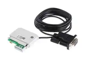
Illustrative purposes only

AL-232CAB
INTERFACE CABLE, ALPHA & PC, 2.5M
⚠️ Reference pricing provided. In case of supply shortages, we will connect you with our trusted procurement partners to ensure your project's continuity.
- Manufacturer: MITSUBISHI
- Product type: Controller Accessories
- SVHC: No SVHC (15-Jan-2018)
- Product Range: ALPHA
- Current Rating: -
| Delivery and price | |
|---|---|
| Units per pack | 10 |
| Price | 60.2 € |
| Current stock | 10+ |
| Lead time | 30 days |
Datasheet

## **FX-Family MELSEC PLC**

# **The world’s favorite micro PLCs**

**10 Million FX PLCs Worldwide /// Over 30 Years Experience /// Expanded Micro PLC Control /// Networking Solutions /// Analog Solutions /// Positioning Solutions ///**

**Global leader /// Global leader /// Global leader /// Global leader /// Global**

## **Global Leader**

The MELSEC FX3U/FX3UC series are the third generation on programmable controllers of the Mitsubushi Electric FX family. They offer improved network capability and solutions for positioning tasks.

## **10 Million FX**

The FX Family of PLCs is the PLC of choice acrosstheworld,industriesandapplications.

Mitsubishi Electric has always worked closely with its customers to design the PLC that they want for their applications. The manufacturing and use of 10 million FX CPUs is a demonstration that this close working relationship has delivered quality, reliability and the product that customers want.

## **Number 1 in the world**

Mitsubishi Electric was shown to be the largest volume producer of PLCs in the world following the 2004 Worldwide PLC survey by the respected American automation research company ARC.

## **Over 30 Years**

The FX Family of PLCs has been an important part of control engineering for over 30 years. Throughout its history, the product has evolved from the original F Series into today's current FX3G series.

The FX Family has proven to be highly reliable and it consistently improves its compatibility with previous PLC generations.

2

ARC is protected by ARC Advisory Group copyright 2004

**/// Contents /// Contents /// Contents /// Contents /// Contents /// Contents**

## **Contents**

|**What makes a world leading PLC?**|**4-5**|
|---|---|
|**Range overview**|**6**|
|**FX3U/FX3UC, a new concept in PLCs**|**7-9**|
|**FX3G, an automation standard**|**10**|
|**FX1N, the modular micro**|**11**|
|**FX1S, micro control**|**12**|
|**Programming and software**|**13**|
|**Networking**|**14**|
|**Analog solutions**|**15**|
|**Positioning solutions**|**16**|
|**Displays solutions**|**17**|
|**Applications**|**18**|


**Section 2: Technical Informations**

3 |

## **What makes a world leading PLC range?**

Adapter or "ADP" units are used on the left hand side of the main PLC unit.

Memory cassette port is located under the removable front cover.

## **Global use**

Wide range power supply means your FX solution will work all over the world.

## **International acceptance**

Shipping approvals such as Lloyds, German Lloyds, ABS, RINA, Det Norse Vetaritas, for example plus CE and E1 compliance for Low Voltage and EMC directives as well as manufacturing to Automotive industry quality levels, make the FX Family PLCs products to trust.

Optional communication boards are available in USB, RS232C, RS422 and RS485 formats.

The standard RS422 Mini-DIN programming port can also be used for HMI connection.

The RUN/STOP switch has become a familiar feature with all FX Family PLCs.

## **Flexible design**

The FX Family is designed so that the main PLC CPU acts as a platform to which you can add and customize the special functions you need – making every FX your personal PLC.

4

**eading PLCs /// World leading PLCs /// World leading PLCs /// World leading**

Main base unit where CPU, I/O and power supply are contained in a single unit.

All FX PLC units can be mounted on a DIN rail or directly mounted with screw fixings.

## **Easy Programming**

The FX Family incorporates an easy programming concept where several complex tasks can be reduced to a single instruction.

## **Fast and reliable**

Simple ribbon connection links each unit together.

Bright LED lamps indicate I/O and power status.

Special function blocks can be added to the right hand communications bus of the PLC.

FX PLCs continually push the limits of high speed operation to process your applications more effectively and accurately. 8098; | POWER , ry BATT as . a #66 7¢ eooe iT **Compatibility** The FX Family of PLCs continues to raise the level of backward compatibility with ree FXav-16EX

The FX Family of PLCs continues to raise the level of backward compatibility with many existing FX PLC programs being transferable. And in later models, sharing common peripherals and special function blocks means even greater protection for your investment in both FX and the machine or process being controlled.

5

## **The power to perform**

**==> picture [464 x 215] intentionally omitted <==**

**----- Start of picture text -----**<br>
/ FX3UC<br>Ultra high speed, maximum<br>performance and a simplified<br>design concept make this the<br>ultimate micro PLC.<br>FX3G<br>Advanced control, multiple<br>communication possibilities<br>and a wide range of options<br>make this PLC an industry<br>leader.<br>FX1N<br>This powerful micro brings<br>the flexibility of the modular<br>PLC design concept but, with<br>14-132 ~ T' |in the ease of use typical of<br>FX Family PLCs.<br>FX1S<br>A compact micro controller<br>for simple applications, sup-<br>ported by a strong communi-<br>oe ssJ FXis cations capability.<br>I/O<br>Performance<br>**----- End of picture text -----**<br>


The FX Family of PLCs builds on previous performance and capability, ensuring you have a comprehensive range of control and automation options to choose from.

**==> picture [319 x 157] intentionally omitted <==**

**----- Start of picture text -----**<br>
Model FX1S FX1N FX3G FX3U FX3UC<br>a<br>100–240V AC, 100–240V AC, 100–240V AC,<br>Power supply 24V DC 12-24V DC 100–240V AC 24V DC 24V DC<br>—_— si<br>30 128<br>Maximum I/O 256** 384* 384*<br>(34 optional) (132 optional)<br>Digital I/O Relay/Transistor Relay /Transistor Relay /Transistor Relay /Transistor Transistor<br>_ [Ta] sss<br>Cycle period/<br>logical 0.55 µs 0.55 µs 0.21 µs or 0.42 µs 0.065 µs 0.065 µs<br>instruction<br>—<br>PLC program<br>2 k steps 8 k steps 32 k steps 64 k steps 64 k steps<br>memory<br>—_<br>**----- End of picture text -----**<br>


Summary table of FX PLCs

Note * : When networked with CC-Link or AS-Interface (Discrete I/O, maximum 256) Note **: When networked with CC-Link or AS-Interface (Discrete I/O, maximum 128)

## **A solution for every application**

Micro PLCs have opened up a world of opportunities in Industrial Automation due to their small size and low cost. Now many applications benefit from enhanced performance, easier manufacturing, maintenance and greater reliability.

The FX Family has been a part of this revolution for over 30 years and has developed and redeveloped a range of products to suit most applications. The FX Family consists of four main ranges which are distinct and independent but compatible.

Depending on your application and control needs, you can choose from; the simple FX1S CPU, the modular FX1N range, the powerful FX3U and now the current and dynamic FX3G.

With the FX Family there really is a solution to most applications.

6 L|

The FX3U has an enhanced communications bus that automatically switches into high speed mode for communication with new FX3U expansion modules.

Full compatibility is still available with FX2N and FX0N expansion blocks, and when these are configured the FX3U automatically reduces the bus speed to suit.

This means greater support for existing installed systems as well as delivering high performance and greater response with new installations.

## **Adapters add flexibility**

## **FX3U a perfect PLC concept**

A major design enhancement of FX3U is the new adapter expansion bus on the left hand side of the FX3U CPU. Through this bus users can add additional analog and temperature units as well as multiple communications and positioning blocks.

The FX3U CPU brings a combination of greater flexibility and increased performance to the FX Family.

## **New high speed bus**

The FX3U design has increased the opportunity to configure the PLC directly for your needs.

Following the standard FX Family configuration, the FX3U CPU can be expanded to the right hand side using a wide range of options. These include input and output blocks as well as special function blocks such as analog, pulse train and network communication units.

FX3U has a unique new system of directly programmable adapters.

However, the major benefit for the user is that the analog and positioning adapter units no longer require the use of the traditional To/From instruction to configure and operate.

All control is through direct access data registers and setting bits. This means quicker set-up, easier use, and above all much higher processing speeds.

The FX3U can use new FX3U blocks as well as standard FX2N and FX0N expansion blocks..

7 _

## **FX3U/FX3UC. More power. More performance.**

**==> picture [428 x 75] intentionally omitted <==**

**----- Start of picture text -----**<br>
FX3U/FX3UC Base Unit Expansion I/O<br>Maximum<br>Network master 256 I/O System Maximum<br> mimo fi _ 384 I/O<br>anne a<br>B Remote I/O Remote I/O Remote I/O Maximum EY + Ei < =<br>Remote network stations 256 I/O<br>**----- End of picture text -----**<br>


FX3U/FX3UC provides additional I/O and networking capacity.

**==> picture [138 x 34] intentionally omitted <==**

**----- Start of picture text -----**<br>
Basic 0,065ps FAST<br>instruction 0,08<br>Applied 0,642us FAST<br>instruction (MOV) 1,52<br>**----- End of picture text -----**<br>


FX3U/FX3UC provides increased performance in all areas.

Note: 4.5 times increase in speed is measured under the following conditions: program capacity=16 k step, with an I/O usage of 144 points. Program scan time is then; FX3U/FX3UC: 4.6 ms and FX2N: 21.0 ms, an increase in processing speed of 4.56 times.

**==> picture [148 x 54] intentionally omitted <==**

**----- Start of picture text -----**<br>
Auxilliary Relay (M) 7680 points FX3U/FX3UC<br>| 3072 points re a |Il<br>State Flags (S) 4096 points<br>1000 points<br>Timers (T) 512 points<br>256 points<br>Data Registers (D) 40768* points<br>8000 points *Includes R Registers<br>**----- End of picture text -----**<br>


FX3U/FX3UC offers increased resources as well as increased performance.

## **Increased I/O capacity**

## **5 times more data storage**

With enhanced networking functions, the FX3U/FX3UC requires an increased input/ output (I/O) range. FX3U/FX3UC can support systems with combined local I/O and networked I/O up to a total of 384 I/O points. For users, this means increased system control and added possibilities for advanced networks.

With a larger program memory comes the need for more operational devices such as timers, state flags, auxiliary relays and data registers. The FX3U/FX3UC has increased capacity in all of these major areas making program construction easier. Data register capacity has increased by a factor of 5 reflecting the needs of users who have an increased requirement to log operation information against products or batches of products being manufactured.

In addition FX3U/FX3UC also fully supports Profibus/DP as well as Ethernet using TCP and UDP protocols.

A typical example of this can be found in the Food and Pharmaceutical industries. Here exact process data such as oven temperatures and cooking times or quantities of ingredients mixed need to be stored against production batches – all this requires increased data handling and data capacity within the PLC.

## **Up to 4.5 times faster**

This means the PC MIX value has been greatly improved with basic instructions now being processed in 0.065 µsec.

For users this means quicker program **75 new** response and more accurate process performance as inputs, outputs and actions **instructions** are processed and monitored more times per second. The FX3U/FX3UC has 75 new

The FX3U/FX3UC has 75 new instructions in comparison with FX2N. This now makes available 249 instructions for program creation. All of the instructions follow the traditional FX Applied instruction concept designed to make the task of application building and program writing easier and quicker, with less chance for errors.

## **8 times more**

## **memory**

FX3U/FX3UC comes with a standard internal memory of 64 k steps, which is 8 times more memory than FX2N.

More memory means users can write larger and more complex programs, store more data in file registers, or take greater advantage of using IEC 61131-3 style programming tools.

8

New instructions include greater control over data processing with a range of new comparison and string manipulation commands.

**LOGE (Nr. 125)**

Calculates the natural logarithm in floating point **SORT2 (Nr.149)** Sort tabulated data

**TBL (Nr. 152)** Batch data positioning mode **BAND (Nr.257)** Defines a band or range of valid numbers **IVWR (Nr.273)** Write parameter to inverter

Some examples of new instructions from the FX3U/FX3UC.

**==> picture [238 x 196] intentionally omitted <==**

**----- Start of picture text -----**<br>
GOT1000<br>RS 232<br>RS 422<br>USB<br>RS 485 Inverter multidrop<br>1S<br>ae @<br>Inverter 1 Inverter 8<br>**----- End of picture text -----**<br>


FX3U/FX3UC has a range of flexible communication options.

## **Simple high speed positioning**

The FX3U/FX3UC has been designed with six high speed counters that can each count up to 100 kHz simultaneously per channel. This, combined with three 100 kHz pulse train outputs, means users can directly configure simple 3-axis positioning systems without the use of additional modules.

Adapter modules increase positioning performance.

However, the new high speed counter ADP and pulse train ADPs can provide the FX3U/FX3UC with maximum positioning performance. Each unit can process signal speeds of up to 200 kHz.

## **A great communicator**

FX3U/FX3UC has strengthened the communications capability of the FX Family even further.

The new adapters allow up to three RS communication channels to be operated simultaneously allowing multiple HMIs to be connected to a single FX3U/FX3UC CPU or combinations of HMIs, third party devices and programming tools – the choice is yours.

The FX3U/FX3UC also supports a wide range of network options including AS-interface, Profibus-DP, CC-Link, DeviceNet, CANopen as well as Ethernet.

The FX3UC is the ideal choice for applications where there is not much space for the controller hardware. The smallest base unit with 8 digital inputs and 8 transistor outputs takes up just 27 % of the space required for a comparable FX3U unit – and yet the FX3UC incorporates all the features of the FX3U.

The connections for the FX3UC inputs and outputs on the front side can be wired with ribbon cable connectors. For this purpose system cabling sets and remote I/O terminal blocks for easy and fast connections are available.

## **FX3U/FX3UC at a glance**

## **I/O range**

16–384 (Discrete I/O, maximum 256)

**Program memory** 64 k steps (standard)

**Basic instruction processing** 0.065 µsec/logical instruction **Analog signal processing** Up to 80 analog inputs, Up to 48 analog outputs

**Analog resolution** 8, 12 and 16 bits

## **Analog options**

19 analog input, output and temperature blocks available for selection

**Positioning** Internal: 6 high speed counters (100 kHz) 2 high speed counters (10 kHz) 3 pulse train outputs (100 kHz), transistor unit only External (FX3U only): High speed counter block (50 kHz) High speed counter ADP module (200 kHz) Pulse train ADP (200 kHz) Pulse train output block (1 MHz)

9 LJ

## **FX3G an industry standard**

## **Highly flexible**

A dual bus architecture provides flexible expansion possibilities and with the ability to handle analog, high speed, positioning, and inverter control, the FX3G is able to successfully adapt to a range of applications in industry areas such agriculture, water processing, material handling, food processing and more.

## **The great communicator**

With a wide range of network and serial protocols available, such as Ethernet, CC-Link and Modbus, the FX3G enables seamless integration and data communications between both Mitsubishi Electric and third-party devices. Furthermore, a built-in USB port permits convenient connection

FX3G PLCs are used in many applications for processing and packaging as well chilled storage and transportion of food items.

to any PC or laptop. **Customized control FX3G at a** The FX3G is an introductory compact PLC **glance** and is the newest addition to the FX3 series, designed for simple yet perform- **I/O range** ance-critical applications that require dis14–256 (Discrete I/O, maximum 128) crete control of up to 128 local I/O or up to **Program memory** 256 I/O with CC-Link remote I/Os. 32 k steps (internal) Incorporating innovative FX3 series tech- **Basic instruction processing** nology the customer is presented with a 0.21 µs or 0.42 µs/logical instruction suite of benefits. These include a large pro- **Analog signal processing** gram memory to implement sophisticated Up to 74 analog inputs algorithms plus high speed execution to Up to 41 analog outputs **Analog resolution** enhance system productivity. 8, 12 and 16 bit **Analog options** 19 analog input, output and temperature blocks available for selection **Positioning** Internal: Up to 4 high speed counters (max. 10kHz) up to 2 high speed counters (max. 60kHz) up to 3 (2) pulse train outputs (100 kHz) on a- Pt len Sai = i = FX3G has the versatility to handle applications from a wide range of industries.

Since its launch, the FX3G has been a standard of micro PLC control.

10 L|

## **FX1N the modular micro**

## **Powerful performance**

The FX1N saves space, cost and engineering time with the use of powerful, built in, positioning tools such two 100 kHz pulse train outputs and up to two 60 kHz high speed counters. These can be used to create simple 2-axis positioning systems, linked to servo amplifiers or stepper motor drivers without the need for additional PLC hardware saving space, cost and engineering time.

FX1N has six shipping approvals. It has been used in applications from controlling temperature in containers to managing diesel engines.

The FX1N provides a simple introduction to modular micro control offering comprehensive functionality and expansion options.

## **Compatibility cuts costs**

## **FX1N at a glance**

**I/O range** 14–132

**Program memory** 8 k steps (standard)

**Basic instruction processing** 0.55 µsec/logical instruction **Analog signal processing** 66 analog inputs 33 analog outputs

**Analog resolution** 8, 12 and 16 bits

**Analog options**

The FX1N offers comprehensive expansion options.

The FX1N provides many user benefits including excellent compatibility with other FX Family PLCs. The FX1N is upwardly compatible to the FX2N/FX3G using many of the FX2Ns I/O and special function blocks. It also shares the same programming structure as the FX1S. This means that users benefit from learning and using one PLC programming syntax; resulting in faster program development and reduced programming errors.

12 analog input, output and temperature blocks available for selection

**Positioning** Internal:

2 high speed counters 60 kHz, 4 high speed counters 10 kHz 2 pulse train outputs (100 kHz), transistor unit only

In addition, users benefit from a reduced stock and spare parts requirement as the FX1N uses the same expansion boards as the FX1S and the same special function and expansion I/O blocks as the FX2N.

11

## **FX1S micro control**

## **Remote control**

The FX1S has an additional range of BD expansion boards providing RS232, RS485 and RS422 communications options. These can be used to connect and control various third party products such as bar code readers or panel printers.

## **Simple programming**

The FX Family has a simple programming structure combining Basic and Applied instructions. The Basic instructions are common to all FX Family PLCs. Applied instructions provide the specialist control options such as data comparisons, PID and communications control, all of which are available on FX1S. As each FX PLC range increases in capability (FX1S, FX1N, FX3G, FX3U/FX3UC) so do the number of available Applied instructions.

## **FX1S at a glance**

FX1S has been used in a wide range of embedded control applications.

## **Fit and forget**

Typically FX1S applications are small, embedded control functions that are hidden away or unaccessible under normal maintenance activities. This is why the FX1S has been designed to be a robust low maintenance PLC. Features such as the maintenance free, 2000 step EEPROM memory and real time clock management all help to make the FX1S a self managing system, reducing the impact on the maintenance engineer.

FX1S offers communication and real time control from a single unit.

**I/O range** 10–34

**Program memory** 2 k steps (standard) **Basic instruction processing** 0.55 µsec/logical instruction **Analog signal processing** Up to 2 points **Analog resolution** 12 bits

**Analog options** 2 analog input BD board 1 analog output BD board **Positioning** Internal: 2 high speed counters 60 kHz, 4 high speed counters 10 kHz 2 pulse train outputs (100 kHz), transistor unit only

Example of connectivity to 3rd party products

12 LO

**/// Programming /// Programming /// Programming /// Programming ///**

## **Progressive software concepts**

The Mitsubishi FX PLC Family has a worldwide reputation for reliability, performance and ease of use. These key values have also been used to form Mitsubishi’s integrated software concept, MELSOFT.

## **Productivity tools**

Programming software for PLCs is constantly evolving. Users are placing more focus on reusable program code and function block concepts. This helps to reduce errors, reduce programming time and to help manage the whole programming process – increasing overall productivity.

## **Simple and intuitive**

GX Developer offers ease of use for programmers of all skill levels.

The key to any good software is that it is simple to use. Mitsubishi’s GX Developer PLC programming packages have achieved this by using intuitive design.

## **One step further with iQ Works**

Mitsubishi Electric's iQ Works software is a suite of four MELSOFT software packages that enable intuitive programming and setup of an iQ Platform system, including system/network configuration, Q and FX Series programming, Q Motion Controller and Servo setup, GOT1000 HMI screen design. This next generation software provides a fully customizable user friendly environment with the developers in mind.

## **First time user?**

For users who do not have the time to take local training, there is the option of using Mitsubishi’s home study software, FX-TRN-BEG, where PLC programs can be created, simulated and debugged in the safety of a PC simulation.

They also have comprehensive help functions and an advanced communications layer, ensuring safe reliable communication to the target PLC.

Often the biggest cost on a project is engineering time.

## **Choose what you need**

GX Developer offers users the chance to program all Mitsubishi MELSEC PLCs from a single package. However, for users who only need support for FX based systems there is GX Developer FX.

Mitsubishi also provide GX IEC Developer packages, providing IEC61131-3 compliant programming in; Instruction List, Ladder, Function Block, Structured Text - and SFC formats. Using standard proaa E gramming languages, like IEC61131-3, on 7a large programming projects can help Ry users save costs by creating reusable PLCcode and Function Blocks.

Learning to program can be achieved quickly using interactive software.

MELSOFT is a wide range of software solutions designed to optimize your plant productivity.

13

## **Networking and communication solutions**

## **Remote maintenance**

With communications technology it is now possible to put PLC control in the most remote locations. Using a PLC with a RS232 interface to a telemetry solution, such as a GSM modem, allows the user the ability to remotely monitor and maintain the system. It can also allow the remote system to send alarm messages, warnings or general status information back to the user’s central data processing centre.

FX Family PLCs have a wide range of communications options.

Applications are often required to integrate between each other across a factory, to report production or tracking data back for office based processing and in some cases be remotely monitored and maintained when the application is in an inaccessible location. The FX Family of PLCs has evolved to match this demand at all levels.

## **Networks make sense**

Networked solutions to complex applications often make the overall solution easier to achieve and more cost effective. For example a conveyor system integrated with a warehouse pick and place system may extend over many hundreds of meters, and by using a fieldbus, such as CCLink, wiring, troubleshooting and maintenance can be dramatically reduced.

Example of remote pumping station.

## **Easy communications**

Today’s FX Family of PLCs share a basic communication concept where additional RS232, RS422 or RS485 communications boards can be added to the main base unit without increasing the required cabinet space. These can then be used for communication to various third party devices like bar code readers, printers and modems.

FX Family PLCs, such as FX1N, FX3G, FX3U and FX3UC, have a wider range of communications modules. These include options for connection to open and bespoke networks such as Ethernet, Profibus-DP, CC-Link, DeviceNet, CANopen, AS-interface or Modbus for example.

14 L|

## **Analog solutions**

Analog control is one of the most important areas for any automation system. Critically for users the concern is to match the performance demanded by the application to the available solutions in a cost effective way.

**==> picture [137 x 205] intentionally omitted <==**

**----- Start of picture text -----**<br>
Example: D-A<br>control can be<br>Inverter<br>used to set the<br>speed of an<br>inverter driving<br>a motor.<br>Example:<br>Temperature<br>control keeps<br>the liquid at the<br>correct viscosity.<br>**----- End of picture text -----**<br>


## **Where is analog used?**

Analog control is widely used. In simple terms it allows a variable signal to be used to control items such as a motor’s speed or to sense inputs such as fluid levels.

## **Digital to analog (D-A) control**

Here a digital PLC value is output as an analog signal. It can be used, for example, to send a speed command to an inverter which in turn causes the motor to increase or decrease speed.

or decrease speed. Example: A-D control ) **Analog to digital (A-D) control** can be used to control the fillIn this type of control a variable signal is < ing speed of sent to a PLC where it is converted in to a the container. direct digital value. An example of this could be the measurement of the level of a é liquid in a storage tank so that the exact amount of stored liquid can be controlled by the PLC. y

In this type of control a variable signal is sent to a PLC where it is converted in to a direct digital value. An example of this could be the measurement of the level of a liquid in a storage tank so that the exact amount of stored liquid can be controlled by the PLC.

## **Temperature control**

Temperature control is the third type of analog control. An example of use could be where the temperature of a furnace is measured and compared by the PLC against a set range. Additional heating or cooling can then be applied to maintain a constant temperature.

Analog solutions are an important part of control engineering and can be used to simplify and accurately control actions happening in the production environment.

## **22 solutions to choose from**

The FX Family offers a wide range of analog solutions from 1 and 2 channel BD boards for FX1S up to 8 channel input blocks like the FX2N-8AD where temperature, voltage and current input can be mixed on the same block. FX analog blocks also come in a range of resolutions from 8 bit up to 16 bit signal processing. Overall there are 22 different analog options available to users of the FX PLC Family.

With this range of choice and flexibility it is sure that there will be a solution here for most applications.

Example of temperature control.

15

## **Positioning solutions**

X-Y table for simple shaping

The larger the range of output pulse frequencies available means greater speed and/or accuracy is achievable. For example, if a stepper motor with a larger number of steps is used, the travel distance per step can be reduced, resulting in an increased system accuracy.

## **High speed counter input**

When a motor is being driven, its relative position can be controlled by counting the number of output pulses.

However, for a more accurate process, reading the actual position from an encoder feedback directly into a high speed counter is preferred. This helps to overcome issues of backlash and slippage as the actual position is measured and not assumed.

Horizontal drill station Vertical drill station

Simple positioning solutions can be effectively managed within a standard FX PLC.

> Using simple positioning solutions canhelp increase the accuracy of the work **Typical**

> process, reduce waste and rework as well asprovide a higher quality of production. **applications**

Simple positioning applications typically involve independently controlled operational axis and can sometimes have many requirements. In the example of an X-Y table, a relative position is achieved by driving each axis until its target position is achieved, regardless of what happens with the other axis. There are two main elements to achieve this type of positioning control.

## **Positioning built in as standard**

FX PLCs come with high speed counters (in some cases up to 100 kHz) and pulse train outputs (also in some cases up to 100 kHz) as standard. The high speed counters can be configured in single pulse train inputs, The high speed counters can be configured in a single or two phase input.

Pulse train outputs can be configured to provide continuous pulse streams at different frequencies or a set quantity of pulses at a single frequency.

There are also optional modules and adapters that can provide additional high speed counters with performance up to 200 kHz. The same is true for pulse train outputs with 200 kHz and 1 Mpps (1 MHz) output options available.

## **Pulse train outputs**

A stream of output pulses can be used as a drive signal to a line driver, stepper motor or servo amplifier, which then causes the connected motor to perform the positioning activity.

Example of conveyor belt control.

16 O

## **Display solutions**

An increasingly important area of any automation solution is the reporting and display of operational information. This data enables operators, maintenance teams and business managers to make informed decisions in the best interests of the business.

## **The right tool for the right job**

For maximum efficiency, each user requires access to information at their work place in a form that highlights the important data for them first. This means a range of different tools are required. As an example, here are three possible scenarios.

## **The machine operator**

Machines often have a lot of manufacturing debris around or are subject to hygienic cleaning as in the food industry. Any display located in this environment would need to have a high Ingress Protection (IP) rating, indicating a high degree of waterproofness.

## **The maintenance team**

The critical information for a maintenance engineer is the error and diagnostic data within the PLC as this is used to diagnose any process problems. However, additional

The FX3U-7DM can be directly mounted within the PLC (FX3U) or mounted on the front cabinet.

information regarding the operational "hours run" or cycles processed, which could be called soft information as it is calculated on operational parameters, could allow the maintenance engineer to predict possible failure and arrange preventative maintenance.

Access to this data could be through the machine operator's terminal, across a network or through a dedicated display mounted inside or on the control cabinet itself.

## **Data the way you want it**

Mitsubishi offers a wide range of visualization solutions from simple data displays such as the FX3U-7DM, advanced Graphic Operator Terminals like the GOT1000 Series and E1000 Series, and a wide choice of software solutions from the MELSOFT software suite.

This powerful combination of hardware and software means there is a cost effective solution for most applications.

The GOT1000 is a typical HMI.

## **The business manager**

In the food industry hygiene is very important.

It may also be a benefit to the operator to have a large and clear display to reduce the chances for error from misreading, due to poor light or small fonts being used. It is also recognized that the use of graphics also reduces the chances for reading errors with complex data.

In a production controllers office it would be better to display information through a network to their existing desktop PC. In this application a piece of software such as an OPC server/client, a Java applet, an Active X control or a SCADA system would allow lots of data from lots of sources to be displayed in a clear and concise way giving the production controller the overview of the business operation that they need.

17 =

**Application solutions /// Application solutions /// Application solutions ///**

## **Where have FX PLCs been used?**

## Leisure

- Multiplex cinema projection

- Animated mechatronics (museums/theme parks)

## Medical

- Respiration machine testing

- Sterilization

## Pharmaceutical/chemical

- Dosing control

- Polution measurement systems

- Cryogenic freezing

- Gas chromotography

- Packaging

## Plastics

- Plastic welding systems

- Energy management systems for injection molding machines

- Loading/unloading machines

- Blow molding test machines

- Injection molding machines

Sanitation management on Eurostar rollingstock.

Customer applications with FX PLCs have been wide spread from critical applications in pharmaceutical industries to sublime applications in the leisure industry. However, the FX PLC Family still remains the PLC of choice for many machine builders as it is flexible, compact and easy to use, which is why it is so often used.

Here are just a few examples of applications that customers have completed in the past

## Printing

## Textiles

## Transportation

- Sanitation on passenger ships

- Sanitation on rail rolling stock

- Fire tender, pump management

- Waste disposal truck management

## Utilities

- Waste water treatment

- Fresh water pumping

## Agriculture

- Plant watering systems

- Plant handling systems – Saw mill (wood)

## Building management

- Smoke detection monitoring

- Ventilation and temperature control

- Lift (elevator) control

- Automated revolving doors

- Telephone management

- Energy management

- Swimming pool management

## Construction

- Steel bridge manufacturing

- Tunnel boring systems

Swimming pools are managed using FX PLCs.

## Food and drink

- Bread manufacture (mixing/baking)

- Food processing (washing/sorting/ slicing/packaging)

18

**ALPHA /// FX1S /// FX1N /// FX3G /// FX3U /// FX3UC ///**

## **Technical Information Section**

**==> picture [596 x 43] intentionally omitted <==**

## **Further Publications within the PLC Range**

## **System Q Family**

##

Product catalogues for programmable logic controllers and accessories for the further MELSEC PLC series

## **HMI Family**

Product catalogue for operator terminals, supervision software and accessories

## **Inverter Family**

Product catalogue for frequency inverters and accessories

## **Servo and Motion Systems**

Product catalogue for servo amplifiers and servo motors as well as motion controller and accessories

## **Robots Family**

Product catalogue for industrial robots and accessories

## **Low Voltage Switchgears**

Product catalogue for low voltage switchgears, magnetic contactors and circuit breakers

## **Automation Book**

Overview on all Mitsubishi automation products, like frequency inverters, servo/motion, robots etc.

## **More information?**

This product catalogue is designed to give an overview of the extensive range of FX Family of MELSEC PLCs. If you cannot find the information you require in this catalogue, there are a number of ways you can get further details on configuration and technical issues, pricing and availability.

For technical issues visit the www.mitsubishi-automation.com website.

Our website provides a simple and fast way of accessing further technical data and up to the minute details on our products and services. Manuals and catalogues are available in several different languages and can be downloaded for free.

For technical, configuration, pricing and availability issues contact our distributors and partners.

Mitsubishi partners and distributors are only too happy to help answer your technical questions or help with configuration building. For a list of Mitsubishi partners please see the back of this catalogue or alternatively take a look at the "contact us" section of our website.

## **About this product catalogue**

This catalogue is a guide to the range of products available. For detailed configuration rules, system building, installation and configuration the associated product manuals must be read. You must satisfy yourself that any system you design with the products in this catalogue is fit for purpose, meets your requires and conforms to the product configuration rules as defined in the product manuals. Specifications are subject to change without notice. All trademarks acknowledged.

© Mitsubishi Electric Europe B.V., Factory Automation - European Business Group

_**2**_

**MITSUBISHI ELECTRIC**

**CONTENTS ///**

**1**

**2**

**4**

**5**

**6**

**7**

## **System Description**

� ALPHA and MELSEC PLC system . . . . . . . . . . . . . . . . . . . . . . . . . . . . . . . . . . . . . . . . . . . . . . . . . . . . . . . . . . . . . . . . . . . . . . . . . . . 4 � Extension modules and special function modules . . . . . . . . . . . . . . . . . . . . . . . . . . . . . . . . . . . . . . . . . . . . . . . . . . . . . . . . . . 6 **1 ALPHA Controllers** � Base units . . . . . . . . . . . . . . . . . . . . . . . . . . . . . . . . . . . . . . . . . . . . . . . . . . . . . . . . . . . . . . . . . . . . . . . . . . . . . . . . . . . . . . . . . . . . . . . . 8 � Extension units and accessories . . . . . . . . . . . . . . . . . . . . . . . . . . . . . . . . . . . . . . . . . . . . . . . . . . . . . . . . . . . . . . . . . . . . . . . . . . 11 **2 MELSEC FX Base Units** � FX1S series . . . . . . . . . . . . . . . . . . . . . . . . . . . . . . . . . . . . . . . . . . . . . . . . . . . . . . . . . . . . . . . . . . . . . . . . . . . . . . . . . . . . . . . . . . . . . . 13 � FX1N series . . . . . . . . . . . . . . . . . . . . . . . . . . . . . . . . . . . . . . . . . . . . . . . . . . . . . . . . . . . . . . . . . . . . . . . . . . . . . . . . . . . . . . . . . . . . . 16 � FX3G series . . . . . . . . . . . . . . . . . . . . . . . . . . . . . . . . . . . . . . . . . . . . . . . . . . . . . . . . . . . . . . . . . . . . . . . . . . . . . . . . . . . . . . . . . . . . . 19 � FX3U series. . . . . . . . . . . . . . . . . . . . . . . . . . . . . . . . . . . . . . . . . . . . . . . . . . . . . . . . . . . . . . . . . . . . . . . . . . . . . . . . . . . . . . . . . . . . . . 22 � FX3UC series . . . . . . . . . . . . . . . . . . . . . . . . . . . . . . . . . . . . . . . . . . . . . . . . . . . . . . . . . . . . . . . . . . . . . . . . . . . . . . . . . . . . . . . . . . . . 26 **3 MELSEC FX Extension Units** � Powered compact extension units. . . . . . . . . . . . . . . . . . . . . . . . . . . . . . . . . . . . . . . . . . . . . . . . . . . . . . . . . . . . . . . . . . . . . . . . 29 � Unpowered modular extension blocks. . . . . . . . . . . . . . . . . . . . . . . . . . . . . . . . . . . . . . . . . . . . . . . . . . . . . . . . . . . . . . . . . . . . 31 **4 MELSEC FX Special Function Modules** � Analog modules . . . . . . . . . . . . . . . . . . . . . . . . . . . . . . . . . . . . . . . . . . . . . . . . . . . . . . . . . . . . . . . . . . . . . . . . . . . . . . . . . . . . . . . . . 33 � Temperature control modules/Data logger modules . . . . . . . . . . . . . . . . . . . . . . . . . . . . . . . . . . . . . . . . . . . . . . . . . . . . . . 36 � High-speed counter modules . . . . . . . . . . . . . . . . . . . . . . . . . . . . . . . . . . . . . . . . . . . . . . . . . . . . . . . . . . . . . . . . . . . . . . . . . . . . 37 � Positioning modules. . . . . . . . . . . . . . . . . . . . . . . . . . . . . . . . . . . . . . . . . . . . . . . . . . . . . . . . . . . . . . . . . . . . . . . . . . . . . . . . . . . . . 38 � Network modules. . . . . . . . . . . . . . . . . . . . . . . . . . . . . . . . . . . . . . . . . . . . . . . . . . . . . . . . . . . . . . . . . . . . . . . . . . . . . . . . . . . . . . . . 39 � Communications modules, Interface modules . . . . . . . . . . . . . . . . . . . . . . . . . . . . . . . . . . . . . . . . . . . . . . . . . . . . . . . . . . . . 45 � Adapter boards and communications adapter . . . . . . . . . . . . . . . . . . . . . . . . . . . . . . . . . . . . . . . . . . . . . . . . . . . . . . . . . . . . 46 � Interface adapters . . . . . . . . . . . . . . . . . . . . . . . . . . . . . . . . . . . . . . . . . . . . . . . . . . . . . . . . . . . . . . . . . . . . . . . . . . . . . . . . . . . . . . . 49 **5 Accessories** � Expansion Adapter . . . . . . . . . . . . . . . . . . . . . . . . . . . . . . . . . . . . . . . . . . . . . . . . . . . . . . . . . . . . . . . . . . . . . . . . . . . . . . . . . . . . . . 50 � Memory media . . . . . . . . . . . . . . . . . . . . . . . . . . . . . . . . . . . . . . . . . . . . . . . . . . . . . . . . . . . . . . . . . . . . . . . . . . . . . . . . . . . . . . . . . . 50 � External Terminal Blocks . . . . . . . . . . . . . . . . . . . . . . . . . . . . . . . . . . . . . . . . . . . . . . . . . . . . . . . . . . . . . . . . . . . . . . . . . . . . . . . . . 51 � Power supply units . . . . . . . . . . . . . . . . . . . . . . . . . . . . . . . . . . . . . . . . . . . . . . . . . . . . . . . . . . . . . . . . . . . . . . . . . . . . . . . . . . . . . . 53 � Backup batteries, Cables . . . . . . . . . . . . . . . . . . . . . . . . . . . . . . . . . . . . . . . . . . . . . . . . . . . . . . . . . . . . . . . . . . . . . . . . . . . . . . . . . 53 � Display modules. . . . . . . . . . . . . . . . . . . . . . . . . . . . . . . . . . . . . . . . . . . . . . . . . . . . . . . . . . . . . . . . . . . . . . . . . . . . . . . . . . . . . . . . . 55 **6 Dimensions** � Base and extension units. . . . . . . . . . . . . . . . . . . . . . . . . . . . . . . . . . . . . . . . . . . . . . . . . . . . . . . . . . . . . . . . . . . . . . . . . . . . . . . . . 56 � Special function modules . . . . . . . . . . . . . . . . . . . . . . . . . . . . . . . . . . . . . . . . . . . . . . . . . . . . . . . . . . . . . . . . . . . . . . . . . . . . . . . . 60 � Accessories. . . . . . . . . . . . . . . . . . . . . . . . . . . . . . . . . . . . . . . . . . . . . . . . . . . . . . . . . . . . . . . . . . . . . . . . . . . . . . . . . . . . . . . . . . . . . . 62 **7 Software & Programming** � Trainings and programming software . . . . . . . . . . . . . . . . . . . . . . . . . . . . . . . . . . . . . . . . . . . . . . . . . . . . . . . . . . . . . . . . . . . . 63 � Programming unit . . . . . . . . . . . . . . . . . . . . . . . . . . . . . . . . . . . . . . . . . . . . . . . . . . . . . . . . . . . . . . . . . . . . . . . . . . . . . . . . . . . . . . . 66 **Others** � Approvals . . . . . . . . . . . . . . . . . . . . . . . . . . . . . . . . . . . . . . . . . . . . . . . . . . . . . . . . . . . . . . . . . . . . . . . . . . . . . . . . . . . . . . . . . . . . . . . 67 � Index. . . . . . . . . . . . . . . . . . . . . . . . . . . . . . . . . . . . . . . . . . . . . . . . . . . . . . . . . . . . . . . . . . . . . . . . . . . . . . . . . . . . . . . . . . . . . . . . . . . . 69

**3**

_**3**_

**MITSUBISHI ELECTRIC**

**/// SYSTEM DESCRIPTION**

## **ALPHA and MELSEC PLC Systems**

Network integration is also supported, making it possible for your FX controllers to communicate with other PLCs, controllers and HMIs. The PLC systems can be configured as local stations in MITSUBISHI networks. In addition these flexible units can also be used as master or slave units on fieldbus’s like Profibus/DP and CC-Link. The MELSEC FX Family controllers also support CANopen, DeviceNet, AS-Interface and Ethernet. Special versions with E-Mark label (ECE requestion) are available upon request for vehicle application.

## **The ALPHA Series**

## **The MELSEC FX Family**

The MELSEC FX family includes a very comprehensive range of base and expansion modules, enabling you to configure a customised system tailored to your precise requirements.

The ALPHA closes the gap between single components and a PLC system. It combines all advantages of a PLC system in a very compact housing and therefore provides a space and cost saving alternative to relays and contactors.

Depending on your application and control needs you can choose from the small, attractively-priced, "stand-alone" FX1S series, the expandable FX1N series or the more powerful FX3G and FX3U series.

The ALPHA series is suited to applications in industrial machines and in automated building services.

**==> picture [511 x 536] intentionally omitted <==**

**----- Start of picture text -----**<br>
Key enhancements in the ALPHA2 include sions with E-Mark label (ECE requestion)<br>a program capacity of 200 function blocks, With the exception of the FX1S all FX series are available upon request for vehicle<br>an extra-large display, expansion options can be expanded to adapt them to the application.<br>and a second communications port. The changing needs of your installations and<br>instruction set, includes math operations, applications.<br>PWM and SMS text messaging functions.<br>All this opens up possibilities for analog<br>and temperature control as well as remote — =<br>operation.<br>a «| De Boe iH mJ<br>| Dasa — ae i |<br>A. SS Re<br>Expandability and Power<br>The MELSEC FX family is highly flexible, expansion capabilities. You can choose Thus the FX3U and FX3UC series give you<br>enabling fast and efficient configuration from I/O expansion modules and special the most powerful CPU for your applica-<br>and programming for the application at function modules for a wide variety of tion and combines all benefits of a com-<br>hand. applications. pact PLC system with the performance of<br>It is the ideal choice, no matter whether a modular PLC system.<br>you need to install a simple control e The FX3G Series<br>application requiring 30 I/Os (FX1S) or a1S) or a) or a The FX3G is an introductory compact PLC<br>demanding, complex system with up to and is the newest addition to the FX3<br>384 I/O points (FX3U).3U).). series, designed for simple yet perfor-<br>The use of memory cassettes can expand mance-critical applications. Incorporating<br>the available programming space on some innovative FX3 series technology the cus-<br>FX Family PLCs while generally providing a tomer is presented with a suite of benefits.<br>long term program storage option for allFX PLC users. In addition, memory cas-FX PLC users. In addition, memory cas- e The FX3U Series ee |<br>settes can also allow programs to be The FX3U series gives you the freedom of<br>switched at very short notice simply by modular expandability, with a wide<br>replacing the cassette. selection of expansion modules and<br>There are five series in the MELSEC FX special function modules.<br>family, each of which is designed for a The FX3U is the fastest PLC systems avail-<br>different application profile: able, with a cycle time of just 0.065 μs per<br>logical instruction. This gives users a<br>The FX1S Series powerful CPU delivering modular PLC<br>The MELSEC FXentry to the MELSEC FX family. With its1S series is the inexpensiveentry to the MELSEC FX family. With its1S series is the inexpensive1S series is the inexpensive series is the inexpensive performance in a compact PLC design. . FX1S | FX1N FX3G FX3U/FX3UC<br>small dimensions it is also an excellent e The FX3UC Series No.ofinputs/outputs Cycletime(µs)<br>alternative to relay/contactor control The performance of the FX3UC is the same3UC is the same is the same Programsteps *Availablewithoptionalcassette<br>24V0VCOM0COM1COM2Y0 Y1 Y2Y3 Y4Y5 14MR-ES/UL 24+0VCOM0Y0COM1Y1COM2Y2COM3Y3Y4 Y5COM4Y6Y7Y10Y11 24MR-ES/UL<br>100-240VAC L NS/SX0X1X2X3X4X5X6X7 100-240VAC L NS/SX0X1X2X3X4X5X6X7X10X11X12X13X14X15<br>ESC<br>OK<br>04 15 26 37<br>POWERRUNERROR<br>FX -14MR<br>04 15 2 3<br>IN<br>OUT<br>(A) (B) 1 2 3 4 5 6 7 8 9 10 11 12 13 14 15<br>AL2-24MR-D<br>MITSUBISHI<br>+ -<br>12 13 14 15048 915 10 1126 37<br>POWERRUNERROR<br>FX -24MR<br>10 1104 15 26 37<br>POWER24V DC<br>1S<br>MITSUBISHI<br>DC INPUT<br>IN<br>1N OUT<br>MITSUBISHI<br>64,000<br>32,00016.000*<br>384<br>8,000*<br>256256<br>2,000 0.55 – 0.7 132 0.55 – 0.7 0.21 – 0.42 0.065<br>34<br>**----- End of picture text -----**<br>


It is the ideal choice, no matter whether you need to install a simple control application requiring 30 I/Os (FX1S) or a1S) or a) or a demanding, complex system with up to 384 I/O points (FX3U).3U).).

The use of memory cassettes can expand the available programming space on some FX Family PLCs while generally providing a long term program storage option for allFX PLC users. In addition, memory cas-FX PLC users. In addition, memory cassettes can also allow programs to be switched at very short notice simply by replacing the cassette.

There are five series in the MELSEC FX family, each of which is designed for a different application profile:

The MELSEC FXentry to the MELSEC FX family. With its1S series is the inexpensiveentry to the MELSEC FX family. With its1S series is the inexpensive1S series is the inexpensive series is the inexpensive small dimensions it is also an excellent alternative to relay/contactor control configurations.

The performance of the FX3UC is the same3UC is the same is the same as that of the FX3U series, but it has more compact dimensions. It is the ideal choice for applications where little space is available for the controller.

## **The FX1N Series**

The CPUs of the FX1N series offer more power than the FX1S series, plus modular

_**4**_

**MITSUBISHI ELECTRIC**

**SYSTEM DESCRIPTION ///**

## **Features**

Themodulardesignofthe FX family makes it extremely flexible, enabling it to be used for a very broad range of applications. You can configure tailor-made systems by combining modules from a variety of different categories (see figure).

All modules are electrically isolated from their environment with optocouplers for maximum reliability.

**==> picture [455 x 193] intentionally omitted <==**

**----- Start of picture text -----**<br>
Digital I/O modules<br>For a variety of signal<br>levels with relay or<br>transistor switches<br>Communications modules DIGITAL<br>INPUTS/OUTPUTS<br>Interface modules with<br>RS232/RS422/RS485 interfaces DIGITALE<br>for the connection of peripher- EIN-/AUSGÄNGE<br>COMMUNI-<br>als and PLC–PLC links. ANALOG<br>CATIONS-<br>INPUTS/<br>Network modules for Ethernet, MODULES CPU OUTPUTS<br>Profibus/DP, CC-Link, AS-Inter- KOMMUNI- ANALOGE<br>KATIONS- EIN-/AUS-<br>face, DeviceNet, CANopen and MODULE GÄNGE<br>for the configuration of propri- POSITIONING<br>etary Mitsubishi networks MODULES<br>POSITIONIER-<br>MODULE<br>**----- End of picture text -----**<br>


## **Analog I/O modules**

## **Positioning modules**

High-speed counter modules with support for the connection of incremental rotary transducers and positioning modules for servo and stepping motor drives

For processing current/voltage signals and temperature registration with a direct connection option for PT100 resistance thermometers and thermocouplers

## **Digital and special function modules – configuration**

The options for using digital and special function modules are dictated by the CPU used in the system.

When calculating the number of special function modules you can use in a system you must take both the number of digital modules and the maximum number of special function modules that can be used into account.

The table on the right provides a simplified guide to the number of modules you can use in each system type. More detailed information and the basic principles of system configuration can be found in the corresponding manuals.

||||||||||
|---|---|---|---|---|---|---|---|---|
|**FX1S**<br>Stand-alonePLC with10/14/20or30I/Os;<br>nospecialfunctionmodulesbut1I/Oadapterboardcanbeinstalled|||||||||
|**FX1N**|||PLC withmax.132I/Os<br>Amaximumof2specialfunctionmodulesordigitalexpansionmoduleswithupto<br>32inputsandoutputs(4x8I/Osor2x16I/Os) oronespecialfunctionmoduleandonedigi-<br>talextensionmodulewithupto16inputsandoutputs(2x8I/Osor1x16I/Os)<br>canbeconnected.||||||
|**FX3G**|||PLC withmax.256I/Os<br>Amaximumof8specialfunctionmodulesanddigitalextensionmoduleswithupto<br>128I/Oscanbeconnectedtotherightsideofthemainunit.Inaddition,amaximumof<br>4specialadaptersfromtheFX3Useriescanbeconnectedtotheleftside.||||||
|**FX3U**|||PLC withmax.384I/Os<br>Totheleftsideofthemainunit,amaximumof10specialadaptersfromtheFX3Useries<br>canbeconnected.Totherightsideofthemainunit,upto8specialfunctionmodulesand<br>digitalextensionmoduleswithupto256I/Oscanbeconnected.||||||
|**FX3UC**|||PLC withmax.384I/Os<br>Totheleftsideofthemainunit,amaximumof6specialadaptersfromtheFX3Useriescan<br>beconnected.Totherightsideofthemainunit,upto4specialfunctionmodulesanddigi-<br>talextensionmoduleswithupto256I/Oscanbeconnected.||||||


_**5**_

**MITSUBISHI ELECTRIC**

**/// SYSTEM DESCRIPTION**

## **The Components for an FX PLC System**

A basic FX PLC system can consist of a stand alone base unit, with the functionality and I/O range increased by adding extension I/O and special function modules. The following section provides an overview of options available.

## **Base Units**

The entire FX PLC range can be AC or DC powered with a mix of input and output styles. The PLCs can be programmed with the user friendly GX or GX IEC Developer programming software, allowing programs to be transferred between different FX PLCs. All PLC base units include an integrated real time clock.

Base units are available with different I/O configurations from 10 to 128 points but can be expanded to 384 points depending upon the FX range selected.

## **Extension Boards**

Extension adapter boards can be installed directly into the base unit and therefore do not require any additional installation space. For a small number of I/O (2 to 4) an extension adapter boards can be installed directly into the (left-hand side) FX1S, FX1N, FX3G or FX3U controller. Interface adapter boards can also provide the FX PLC with additional RS232, RS422, RS485 or USB interfaces. To connect special function modules (e.g. Ethernet module) a communication adapter has to be installed (except FX3UC).

## **Extension I/O Modules**

Unpowered and powered extension I/O modules can be added to the FX1N/FX3U and FX3UC PLCs.

For expansion modules powered by the base unit, the power consumption has to

be calculated as the 5 V DC bus can only support a limited number of expansion I/O (for further details please refer to next page – calculation of the power consumption).

## **Special Function Modules**

A wide variety of special function modules are available for the FX1N, FX3G, FX3U and FX3UC PLCs. They cover networking functionality, analog control, pulse train outputs, data logging function and temperature inputs.

## **Memory extension and operator terminals**

Each FX family base unit can be equipped with a memory cassette. The programming unit interface enables the connection of programming tools like PC and hand held programming units as well as graphical operator terminals.

**==> picture [261 x 84] intentionally omitted <==**

**----- Start of picture text -----**<br>
; i 0 1 2 3 4 5 6 7 —————__<br>8 9 A B C D E F<br>IN<br>ON LINE STATION<br>POWER<br>FX0N-3A<br>OFFOFFONON<br>ERR<br>MODOFFON 0 1 2 3 FX2N-16LNK-M<br>ERROR STATION<br>24+ 24-<br>RUNAA RUNBDG<br>**----- End of picture text -----**<br>


|**ALPHA2**<br>**FX1S**<br>**FX1N**<br>**FX3G**<br>**FX3U**<br>**FX3UC**<br>**Reference page**<br>Extensionsforinside<br>PLC installation<br>Digital<br>11, 45<br>Analog<br>11, 46|**ALPHA2**<br>**FX1S**<br>**FX1N**<br>**FX3G**<br>**FX3U**<br>**FX3UC**<br>**Reference page**<br>Extensionsforinside<br>PLC installation<br>Digital<br>11, 45<br>Analog<br>11, 46|**ALPHA2**<br>**FX1S**<br>**FX1N**<br>**FX3G**<br>**FX3U**<br>**FX3UC**<br>**Reference page**<br>Extensionsforinside<br>PLC installation<br>Digital<br>11, 45<br>Analog<br>11, 46|
|---|---|---|
|||11, 46|
|Extensionmodules<br>(installationoutside<br>thePLC)<br>Digital<br>Analog<br>Temperature|—<br>—|29|
||—<br>—|33|
||—|11, 34|
|Networkmodules<br>AS-Interface<br>CC-Link<br>CANopen<br>Ethernet<br>Profibus/DP<br>DeviceNet<br>ModbusRTU/ASCII<br>SSCNET|—<br>—|12, 39|
||—<br>—|38|
||—<br>—|43|
||—|40|
||—<br>—|41|
||—<br>—<br>—<br>—|43|
||ModbusRTU/ASCII<br>—<br>—<br>—|44|
||—<br>—<br>—<br>—|37|
|Communications<br>boards<br>RS232<br>RS422<br>RS485<br>USB||—<br>48|
||—|—<br>48|
||—|—<br>48|
||—<br>—<br>—<br>—|—<br>47|
|Communications<br>modules<br>RS232<br>RS485|—|44|
||—|44|
|Dedicatedfunction<br>modules<br>Highspeedcounter<br>Positioning|Highspeedcounter<br>—<br>—<br>—<br>—|36|
||—<br>—<br>—<br>—|37|
|Memorycassettes||12, 49|
|ExternalDisplay|—|—<br>54|


onlyviaIEC functionblocks

~~a~~ _**6**_

**MITSUBISHI ELECTRIC**

**SYSTEM DESCRIPTION ///**

## **Calculation of the Power Consumption**

The power consumption figures on the 5 V DC bus for the special function modules are shown in the specifications tables on the following pages.

The maximum permissible currents on the 5 V DC and 24 V DC bus are shown in the table below.

|**Modules**|**Max. current**|
|---|---|
||**5 V bus**<br>**24 V bus**|
|FX3G-14/24M�-ES(ESS)|—<br>400mA|
|FX3G-40/60M�-ES(ESS)|—<br>400mA|
|FX3U-16/32M�-ES(ESS)|500mA<br>400mA|
|FX3U-48–128M�-ES(ESS)|500mA<br>600mA|
|FX3UC-16MT/D(DSS)|600mA<br>—|
|FX3UC-32MT/D(DSS)|560mA<br>—|
|FX3UC-64MT/D(DSS)|480mA<br>—|
|FX3UC-96MT/D(DSS)|400mA<br>—|


The residual currents for the 24 V DC service voltage at different input/output configurations are shown in the tables on the right.

A maximum of 256 I/Os are possible for FX3U/FX3UC (128 I/Os for FX3G).

Max.residualcurrentvalues(inmA)forFX3U-16M�-E�� through FX3U-32M�-E�� for the permissible configuration

**==> picture [259 x 97] intentionally omitted <==**

**----- Start of picture text -----**<br>
40 25<br>32 100 50 0<br>Number of 24 175 125 75 25<br>additional<br>outputs 16 250 200 150 100 50 0<br>8 325 275 225 175 125 75 25<br>0 400 350 300 250 200 150 100 50 0<br>0 8 16 24 32 40 48 56 64<br>Number of additional inputs<br>**----- End of picture text -----**<br>


Max.residualcurrentvalues(inmA)forFX3U-48M�-E�� through FX3U-128M�-E�� for the permissible configuration

|**Number of**<br>**additional**<br>**outputs**|**64**|0|||||||||||||
|---|---|---|---|---|---|---|---|---|---|---|---|---|---|---|
||**56**|75|25||||||||||||
||**48**|150|100|50|0||||||||||
||**40**|225|175|125|75|25|||||||||
||**32**|300|250|200|150|100|50|0|||||||
||**24**|375|325|275|225|175|125|75|25||||||
||**16**|450|400|350|300|250|200|150|100|50|0||||
||**8**|525|475|425|375|325|275|225|175|125|75|25|||
||**0**|600|550|500|450|400|350|300|250|200|150|100|50|0|
|||**0**|**8**|**16**|**24**|**32**|**40**|**48**|**56**|**64**|**72**|**80**|**88**|**96**|
|||**Number of additional inputs**|||||||||||||


An external power supply is necessary, if the residual current for the 24 V supply of the special function modules is not sufficiant.

## **Sample Calculations**

The tables below and on the right show different examples for sample power calculation for a PLC system.

The current values for the special function modules can be found in the specifications on the following pages. Comparison with the current value tables show that the calculated figures for the 5 V bus lie within the allowable ranges. In the example below all units can be supplied sufficiently with the internal 24 V power supply.

|**Module**|**No.**|**24 VDC calculation**|**24 VDC calculation**|**24 VDC calculation**|**5 VDC calculation**|**5 VDC calculation**|
|---|---|---|---|---|---|---|
|||**Current/module**|**Calculation**||**Current/module**|**Total current**|
|FX3U-80MR/ES|1|600mA|+600mA||+500mA|+500mA|
||||||||
|FX3U-4AD|3|90mA|-180mA||110mA|-220mA|
|FX3U-4DA|2|160mA|-320mA||120mA|-240mA|
|FX3U-ENET|1|240mA|-240mA||—|—|
||||**-140 mA !!!**|||**500 –460 mA**|
||||||Result:|**40 mA (OK!)**|
|An external 24 V power supply has to|||||||


An external 24 V power supply has to be added in the example above.

|**Module**|**No.**|**NumberofI/Os**|**NumberofI/Os**|**NumberofI/Os**|**24 VDC calculation**|**24 VDC calculation**|**5 VDC calculation**|**5 VDC calculation**|
|---|---|---|---|---|---|---|---|---|
|||**X**|**Y**|**X/Y**|**Total** �|**Total current** �|**Current/module**|**Total current**|
|FX3U-48MR/ES|1|24|24|—|X=8<br>Y=24<br>➞|+325mA|500mA|+500mA|
|FX2N-16EYR-ES/UL|1|—|16|—|||—|0mA|
|FX2N-8EX-ES/UL|1|8|—|—|||—|0mA|
|FX2N-8EYR-ES/UL|1|—|8|—|||—|0mA|
|FX3U-4AD-PT-ADP|1|—|—|—||-50mA|30mA|-15mA|
|||||||**+275 mA (OK!)**||**+485 mA (OK!)**|
|FX2N-32ER-ES/UL|1|16|16|—|X=16<br>Y=0<br>➞|+150mAresidualcur-<br>rentforextensionunit<br>FX2N-32ER-ES/UL|690mA|+690mA|
|FX2N-16EX-ES/UL|1|16|—|—|||—|0mA|
|FX2N-10PG|1|—|—|8||0mA|120mA|-120mA|
|FX2N-32CCL|1|—|—|8||-50mA|130mA|-130mA|
|Result:||**64 +64 +16 =144!(<256)OK!**||||**+100 mA (OK!)**||**+440 mA (OK!)**|


> � Totalno.ofI/Oswhichareconnectedtoabaseunittocalculatethemax.residualcurrentvalues(seetables) � seetablesabove(max.residualcurrentvalues)

_**7**_

**MITSUBISHI ELECTRIC**

**/// ALPHA SYSTEM OUTLINE**

**1**

## ~~**The ALPHA 2 Series**~~

**==> picture [265 x 41] intentionally omitted <==**

**----- Start of picture text -----**<br>
Up to  15 inputs  can be used as digital The  analog inputs  (0–10 V, 9 bits<br>inputs and up to for (con- resolution) can be used very easily due<br>trollers with 24 V DC supply). to the integrated gain function and a<br>Schmitt-trigger.<br>8 analog inputs<br>**----- End of picture text -----**<br>


**==> picture [514 x 272] intentionally omitted <==**

**----- Start of picture text -----**<br>
The communication with a com-<br>puter and with external periph-<br>erals is supported by the two<br>Integrated calender/real-time function integrated serial interfaces .<br>with up to 1200 switch ON<br>or OFF commands in one program<br>YSproedawsosonesceo: |<br>Ypoospassossegcocc2 A<br>—— ee :<br>Direct programming via<br>8 function keys  on the front control<br>N es Ct— panel without any additional program-<br>qe ming device<br>@<br>‘e) The units can be expanded<br>to additional inputs/outputs<br>with  extension modules  to<br>be mounted directly into the<br>controller<br>Se<br>———<br>Flexible mounting  through integrated<br>nn a<br>DIN rail adapter and screw fixing<br>The program is stored in a maintenance-<br>free  EEPROM  with a memory capacity of<br>5000 bytes.<br>Large  LC display  for programming, A backup battery is not required.<br>entering, and editing plain text,<br>values and bar graphs<br>Password protection<br>can be activated.<br>ESC<br>OK<br>POWER<br>24V DC<br>(A) (B) 1 2 3 4 5 6 7 8 9 10 11 12 13 14 15<br>DC INPUT<br>AL2-24MR-D<br>+ -<br>MITSUBISHI<br>**----- End of picture text -----**<br>


## **Description of the Unit Components**

**==> picture [482 x 280] intentionally omitted <==**

**----- Start of picture text -----**<br>
Power supply<br>terminals<br>Terminals for<br>Mounting hole<br>nN digital/analog inputs<br>Npecoooacaooscso2s2f Connector for PC,<br>Adapter for eT GSM, modem and<br>DIN rail mounting other automation<br>components<br>Slot for q =f mi c<br>= =<br>EEPROM cassetteor connector for Ee eee Operating keys (8 pcs.)<br>programming cable i—3 © SSS<br>\<br>Housing cover<br>(place holder) for the<br>Protective cover Se = extension modules<br>LCD display<br>(4 lines x 12 characters) $$ RY/ Connection for<br>extensions<br>Terminals for<br>digital outputs<br>(A) (B) 1 2 3 4 5 6 7 8 9 10 11 12 13 14 15<br>AL2-24MR-D<br>DC INPUT<br>+ -<br>POWER<br>24V DC<br>ESC<br>OK<br>MITSUBISHI<br>**----- End of picture text -----**<br>


_**8**_

**MITSUBISHI ELECTRIC**

**ALPHA BASE UNITS ///**

**1**

## ~~**Specifications ALPHA 2**~~

## **ALPHA 2 Base Units**

**==> picture [461 x 152] intentionally omitted <==**

**----- Start of picture text -----**<br>
The ALPHA 2 controllers offer simple reliable control for a range<br>of automation applications including lighting, air conditioning,<br>e e security systems, and temperature and water control.<br>) = a<br>Special features:<br>©e Transistor and relay output options<br>© [e] Analog input/output<br>©e High Speed counters up to 1 kHz<br>GGG 0 SS-e° GSM function for communication with mobile phonesLanguage support for 8 different languages<br>SSS|a= e Display unit for messages and function block data<br>e.g. AL2-24M OO -<br>(A) (B) 1 2 3 4 5 6 7 8 9 10 11 12 13 14 15<br>AL2-24MR-D<br>POWER<br>24V DC<br>DC INPUT<br>+ -<br>ESC<br>OK<br>MITSUBISHI<br>**----- End of picture text -----**<br>


The ALPHA 2 controllers offer simple reliable control for a range of automation applications including lighting, air conditioning, security systems, and temperature and water control.

## **Base Units with 10–24 I/Os**

||||||||**AL2-10MR-D**|**AL2-14MR-A**|**AL2-14MR-D**|**AL2-24MR-A**|**AL2-24MR-D**|
|---|---|---|---|---|---|---|---|---|---|---|---|
|**Electrical specifications**||||||||||||
|Integratedinputs/outputs||||||10|10|14|14|24|24|
|Powersupply||||||100–240VAC|24VDC|100–240VAC|24VDC|100–240VAC|24VDC|
|Digitalinputs||||||6|6|8|8|15|15|
|Analoginputs||||||—|6|—|8|—|8|
|Channels||||||—|6|—|8|—|8|
|Integratedoutputs||||||4|4|6|6|9|9|
|||||||||||||
|Max.powerconsumption|||||W|4.9|4.0|5.5|7.5|7.0|9.0|
|Typ.power<br>consumption||||All I/Os<br>ON/OFF|W|3.5/1.85240VAC<br>3.0/1.55120VAC|2.5/0.75|4.5/2.0240VAC<br>3.5/1.5120VAC|4.0/1.0|5.5/2.5240VAC<br>4.5/2.0120VAC|5.0/1.0|
|Weight|||||kg|0.2|0.2|0.3|0.3|0.35|0.3|
|Dimensions(WxHxD)|||||mm|71.2x90x55|71.2x90x55|124.6x90x52|124.6x90x52|124.6x90x52|124.6x90x52|
|||||||||||||
|**Order information**|||||Art. no.|215070|215071|215072|215073|215074|215075|
|||||||||||||
|**Accessories**||||||PowersupplieswithDIN-railorwallmountingpossibilitiesforpoweringthe24VDC modules(refertothepowersupplychapterinthiscatalogue)||||||


_**9**_

**MITSUBISHI ELECTRIC**

**/// GENERAL SPECIFICATIONS**

**1**

## **Environmental Specifications**

||||||||
|---|---|---|---|---|---|---|
|Ambienttemperature<br>Display:-10–55°C,Hardware:-25–55°C (storagetemperature:-30–+70°C)|||||||
|Protectionrating||||IP20|||
|Noiseimmunity||||1000Vppwithnoisegenerator;1µsat30–100Hz,testedbynoisesimulator|||
|Dielectricwithstandvoltage||||3750VAC,>1min.accordingtoEN60730|||
|Allowablerelativehumidity||||35–85%(nocondensation)|||
|Shockresistance||||Acc.toIEC 68-2-27:147m/s2acceleration,11ms3x3directions|||
|Vibrationresistance|||directmounting<br>DINrailmounting|Acc.toIEC-2-6:19.6m/s2acceleration,80min.ineachdirection|||
|||||Acc.toIEC-2-6:9.8 m/s2acceleration,80min.ineachdirection|||
|Insulationresistance||||500VDC,7M�acc.toEN60730-1|||
|Ambientconditions||||Nocorrosivegases,nodust|||
|Certifications||||Pleaserefertopages66–67inthiscatalogue|||


## **Electrical Specifications**

|Powersupply<br>24VDC<br>100–240VAC(50/60Hz)|Powersupply<br>24VDC<br>100–240VAC(50/60Hz)|Powersupply<br>24VDC<br>100–240VAC(50/60Hz)|
|---|---|---|
|InrushcurrentatON||�7.0A(at24VDC)<br>�6.5A(at240VAC)|
|Allowablemomentarypowerfailuretime||5ms<br>10ms|
|**Digital In**|**puts**||
|Inputvolt|age|24VDC<br>(+20%/-15%)<br>100–240VAC<br>(+10%/-15%),50/60Hz|
|Inputcurr|ent|Theinputcurrentchanges<br>dependingonSourceorSink.<br>ForSink:<br>(AL2-10/14/24MR-D)<br>=5.5mA,24VDC<br>ForSource:<br>(AL2-10/14MR-D)<br>=6.0mA,24VDC<br>(AL2-24MR-D)<br>=5.5mA,24VDC<br>I01–I08<br>0.13mA/120VAC*<br>0.25mA/240VAC*<br>I09–I15<br>0.15mA/120VAC*<br>0.29mA/240VAC*|
|Response|time<br>OFF�ON<br>ms<br>ON�OFF<br>ms|10–20<br>35–85ms,120VAC<br>25–55ms,240VAC|
|||10–20<br>35–85ms,120VAC<br>50–130ms,240VAC|
|**AnalogIn**|**puts**||
|Analoginputrange||0–500<br>—|
|Resolution||9bit,(10V/500)<br>—|
|Conversionspeed<br>ms||8<br>—|
|Voltage||0–10VDC<br>—|
|Impedance<br>k�||142±5%<br>—|
|Accuracy||±5%(0.5VDC)<br>—|


|Type|Type|
|---|---|
|Type|Relay|
|Switchingvoltage(max.)<br>V|250VAC,30VDC|
|Ratedcurrent|10M,14M:8A/point<br>24M (001-004):8A/point<br>24M (005-009):2A/point|
|Max.switching<br>load<br>-inductiveload|14M,24M:249VA,250VAC/373VA,250VAC<br>24M:93VA,125VAC/93VA,250VAC|
|Minimumload|10mA,5VDC|
|Responsetime<br>ms|�10|


* Currentleakagefromthesensorsconnectedtotheinputsmightprovideenoughcurrenttoturnthe controllerOn.Donotusetwowiresensors

## **Programming Specifications**

|||||||
|---|---|---|---|---|---|
|Programmingmethod<br>Functionblock||||||
|Programcapacity|||200functionblocksor5000bytes|||
|Programprocessing|||Cyclicprocessingofthestoredprogram|||
|Numberofavailableinstructions|||38differentfunctionblocks|||
|Programstorage|||IntegratedEEPROM andoptionaladditionalEEPROM cassette|||
|Datastorage|||Atvoltagelossthecurrentstatusofvalues,runningtimemeters,andreal-timedataarestoredforupto20days(attemperaturesof0to25°C) through<br>integratedcapacitors|||
|Processingtime|||1ms+20�s/log.instruction(complexcommands500�s/instruction)|||
|Real-timeclock|||Seconds,minutes,hours,dayofweek,month,year(4-digit);accuracy:5s/day;automaticsummerandwintertimetoggling|||
|Programprotection|||Programandkeys(3levels)|||


_**10**_

**MITSUBISHI ELECTRIC**

**EXTENSION MODULES ///**

**1**

**==> picture [65 x 83] intentionally omitted <==**

**----- Start of picture text -----**<br>
NWS SSS<br>00000<br>eSI — =—<br>EO3 EO4<br>OUTPUTRELAY<br>4EYR<br>MITSUBISHI<br>EO1 EO2<br>**----- End of picture text -----**<br>


## **Digital Extension Modules**

Thereare4differentextensionmodulesavailablefortheALPHA2, which allow the controller to be extended through additional inputs or outputs. The modules are inserted directly into the ALPHA 2 and therefore do not take up any additional space.

The AL2-4EX has the additional feature that 2 inputs may be used as high-speed counters with a counting frequency of 1 kHz.

All modules feature photocoupler insulation for all I/Os.

Note: The digital extension modules cannot be used with the AL2-10MR series.

|Digitalextension modulesspecifications|Digitalextension modulesspecifications|Digitalextension modulesspecifications|Digitalextension modulesspecifications|Digitalextension modulesspecifications|Digitalextension modulesspecifications|Digitalextension modulesspecifications|Digitalextension modulesspecifications|Digitalextension modulesspecifications|AL2~~-~~4EX~~-~~A2|**AL2-4EX**|**AL2-4EYR**|**AL2-4EYT**|
|---|---|---|---|---|---|---|---|---|---|---|---|---|
|**Inputs**|||||||||||||
|Integratedinputs|||||||||4|4|—|—|
|Inputvoltage|||||||||220–240VAC|24VDC (+20%,-15%)|—|—|
|Inputcurrent|||||||||7.5mAat240VAC (50Hz),<br>9.0mAat240VAC (60Hz)|5.4mA±1mAat24VDC|—|—|
|**Outputs**|||||||||||||
|Integratedoutputs|||||||||—|—|4|4|
|Outputtype|||||||||—|—|Relay|Transistor|
|Switchedvoltage(max.)||||||||V|—|—|250VAC,30VDC|5–24VDC|
|Ratedcurrent||||||||A|—|—|2Aperoutput|1Aperoutput|
|**Electrical specifications**|||||||||||||
|PowerSupply||||AC range(+10%,-15%)|||||220–240VAC|24VDC|100–240VAC|24VDC|
|**Mechanical specifications**|||||||||||||
|Weight||||||||kg|0.05|0.05|0.05|0.05|
|Dimensions(WxHxD)||||||||mm|53.1x90x24.5|53.1x90x24.5|53.1x90x24.5|53.1x90x24.5|
||||||||||||||
|**Order information**||||||||Art. no.|142522|142521|142523|142524|


Note: EI1andEI2oftheAL2-4EXcanbeusedashigh-speedcounterinputs.Ineachcasetheresponsetimeforthehigh-speedcounterinputswillbe0.5msorless. The AL2-4EX-A2, AL2-4EX, AL2-4EYR and AL2-4EYT modules can not be used with the AL2-10MR series.

## **Analog Extension Modules**

**==> picture [169 x 108] intentionally omitted <==**

**----- Start of picture text -----**<br>
009009<br>OSsase00000| p Z SNS sall te<br>, C0000<br>tes »<br>Se 600600 fa<br>_ iw ><br>600000aes \==s0007SSS V2+ I2+ VI2- J @<br>POWER<br>POWER<br>V1+ V1- V2+ V2-<br>POWER24V DC OUTPUT 0~10V<br>MITSUBISHI<br>V1+ V1- V2+ V2-<br>POWER24V DC OUTPUT 0~10V<br>MITSUBISHI<br>200°C -50°CCH1 Line 200°C CH2-50°C Line<br>450°C -50°CCH1 Line 450°C CH2-50°C Line CH1 CH2<br>L1+ L1- I1- L2+ L2- I2-<br>CH1 CH2<br>L1+ L1- SLD L2+ L2- SLD<br>+ -<br>+ -<br>AL2-2PT-ADPPT100 -50~200°C<br>K-type Thermocouple -50~450°CAL2-2TC-ADP<br>POWER24V DC ANALOGOUTPUT<br>ANALOGOUTPUT 2DA<br>CH1 CH2<br>CH1 CH2<br>MITSUBISHI<br>+ - V1+ I1+ VI1-<br>**----- End of picture text -----**<br>


The analog extension modules significantly increase the range of applications for the ALPHA 2. With these modules it is possible to output voltage or current signals or to measure temperatures.

Three different analog extension modules are available:

The AL2-2DA offers two additional analog outputs for the ALPHA 2 and converts a digital input value into a voltage or a current. This module is inserted directly into the ALPHA 2.

Note: the AL2-2DA cannot be used with the AL2-10MR series.

The AL2-2PT-ADP connects an external PT100 sensor to convert temperature readings into analog signals (0–10 V).

The AL2-2TC-ADP connects thermocouple sensors (K type) to convert temperature readings into analog signals (0–10 V).

|Analog extensionmodules|Analog extensionmodules|Analog extensionmodules|modulesspecifications|modulesspecifications|modulesspecifications|modulesspecifications|modulesspecifications|AL2~~-~~2DA|||||**AL2-2PT-ADP**|**AL2-2TC-ADP**|
|---|---|---|---|---|---|---|---|---|---|---|---|---|---|---|
|**Analoginputs**|||||||||||||||
|Integratedinputs||||||||—|||||2|2|
|Connectabletemperaturesensors||||||||—|||||PT100sensor<br>Temp. coefficient3.850ppm/°C(IEC 751)|Thermocouple(Ktype),isolatedtype<br>(IEC 584-11977,IEC 584-21982)|
|Compensatedrange||||||||—|||||-50–+200°C|-50–+450°C|
|**Analogoutputs**|||||||||||||||
|Integratedoutputs||||||||2|||||—|—|
|Analogoutput|||voltage|||||0–10VDC(5k|Q|1M )<br>a|||—|—|
|range|||current|||||4–20mA(max.500|||QO|)|—|—|
|**Electrical specifications**|||||||||||||||
|Numberofchannels||||||||2|||||2|2|
|PowerSupply||||||||24VDC(-15–+10%),70mA|||||24VDC(-15–+20%),1W|24VDC(-15–+20%),1W|
|**Mechanical specifications**|||||||||||||||
|Weight|||||||kg|0.05|||||0.07|0.07|
|Dimensions(WxHxD)|||||||mm|53.1x90x24.5|||||35.5x90x32.5|35.5x90x32.5|
||||||||||||||||
|**Order information**|||||||Art. no.|151235|||||151238|151239|


_**11**_

**MITSUBISHI ELECTRIC**

**/// EXTENSION MODULES AND ACCESSORIES**

**1**

## **AS-Interface Module AL2-ASI-BD**

**==> picture [65 x 36] intentionally omitted <==**

**----- Start of picture text -----**<br>
occ a<br>{ [2008 ASI+ASI-ASI+ASI-<br>**----- End of picture text -----**<br>


The Actuator Sensor Interface module AL2-ASI-BD in combination with an ALPHA 2 controller facilitates the data communications via an AS-Interface system. The AL2-ASI-BD is attached to an ALPHA 2 series module and forms a slave unit. Up to 4 inputs and 4 outputs can be exchanged with the AS-Interface master.

The addresses of the slave devices in the AS-Interface are assigned either automatically via the master in the network or via a programming device (software).

The maximum communication distance is 100 m without a repeater. If 2 repeaters are used, the distance is extended to up to 300 m.

For the AS-Interface a separate power supply is required. The communication signal is superimposed on the power supply of the AS-Interface bus.

Note: The AL2-ASI-BD cannot be used with the AL2-10MR series.

|Moduletype||Slavemodule|
|---|---|---|
|NumberofI/Opoints||4inputs,4outputs|
|Externalpowersupply||30.5VDC (AS-Interfacepowersupply)|
|Externalcurrentconsumption|mA|Max.40|
|Communicationsprotocol||AS-Interfacestandard|
|Weight|kg|0.05|
|Dimensions(WxHxD)|mm|53.1x90x24.5|
||||
|**Order information**|Art. no.|142525|


## **Memory Cassette AL2-EEPROM-2 Memory Media**

With the AL2-EEPROM-2 memory cassettes, a new program can be transferred to the ALPHA 2 controller’s internal system memory from the cassette, or the program of the internal system memory can be saved to the cassette.

If the memory cassette is used, a certain program can be run temporarily by simply plugging the external memory module onto the ALPHA 2.

After removing the memory cassette, the former program in the internal memory becomes active again.

**==> picture [5 x 32] intentionally omitted <==**

**----- Start of picture text -----**<br>
AL2-EEPROM<br>IN JAPAN<br>MADE<br>**----- End of picture text -----**<br>


The memory cassette AL2-EEPROM-2 is not a memory expansion device, but a medium for data exchange.

|Memorytype||EEPROM|
|---|---|---|
|Application||ALPHA2|
|Memorycapacity||5,000bytes|
|Functionblocks||Max.200|
|Dimensions(WxHxD)|mm|10x45x25|
||||
|**Order information**|Art. no.|142526|


## **Interface Cable AL-232CAB**

The AL-232CAB is an RS232C interface cable. It connects the ALPHA 2 controller to a personal computer running the programming software for the ALPHA 2 controller. The cable ensures a galvanic isolation between the ALPHA 2 controller and the personal computer. The cable AL-232CAB can not be used for any other connection.

## **GSM Cable AL2-GSM-CAB**

**==> picture [141 x 97] intentionally omitted <==**

**----- Start of picture text -----**<br>
AL-232CAB<br>> NN<br>~<br>Ri;<br>ee> Sscar<br>MITSUBISHIELECTRIC<br>AL2-GSM-CABLOT .24<br>**----- End of picture text -----**<br>


**==> picture [42 x 5] intentionally omitted <==**

**----- Start of picture text -----**<br>
AL2-GSM-CAB<br>**----- End of picture text -----**<br>


The GSM AL2-GSM-CAB is an RS232C interface cable and it is used to connect the ALPHA 2 controller to a normal or GSM modem, a personal computer or other serial devices. It can transfer SMS data to a GSM modem for onward transmission to mobile telephones or e-mail addresses. It also permits remote monitoring and remote maintenance.

Note: The above cables cannot be used with the AL2-10MR series.

|Connector<br>Application<br>Length|m|9-pinD-SUBfemaleconnector<br>ALPHA2<->PC<br>2.5|9-pinD-SUBmaleconnector<br>ALPHA2<->PC,modem<br>1.5|
|---|---|---|---|
|||||
|**Order information**|Art. no.|87674|142528|


_**12**_

**MITSUBISHI ELECTRIC**

**BASE UNITS FX1S SERIES ///**

**2**

## **The MELSEC FX1S Series**

All units feature two **analog potentiometer** for setpoint value entry and an **integrated RUN/STOP switch** .

Integration of **interface, extension, and functions adapters** for direct installation in the base unit

**High-speed inputs** for fast counting tasks with counting frequencies of up to 60 kHz and **interrupt processing capabilities**

LOK, <— S KE

The **internal service power supply unit** for 24 V DC has a capacity of 400 mA. Note: service power supply is only available for AC Power Supply types.

**Square pulse output** (thisappliesonlytotransistorunits.) Two **high speed pulse outputs** for frequencies up to 100 kHz for outputting integrated and controlling stepping motors pulse signals **Integrated real-time clock** with year, month, day and time

**Integrated serial RS422 interface** for direct communication with computers

## **Flexible installation** with the

integrated DIN rail adapter and screw fastening holes for mounting on flat surfaces

## **Password access protection**

facility for effective protection of your intellectual property.

Your PLC programs are stored in a maintenance-free **EEPROM user memory** with a capacity of 2,000 program steps, so there is no need for a backup battery to protect against power failures.

## **Description of the Unit Components**

**==> picture [476 x 237] intentionally omitted <==**

**----- Start of picture text -----**<br>
Protective cover<br>Terminal cover<br>: 5000ee2—_<br>Fixing hole<br>Connection of the<br>Terminals for<br>power supply tic ERP E EE<br>digital inputs<br>Adapter interface LEDs for indicating<br>the input status<br>Slot for adapter<br>RUN/STOP switch<br>2 analog potentiometers<br>- o o LEDs for indicating the<br>Connection for operating status<br>programming units LEDs for indicating<br>the output status<br>Service voltage<br>source<br>Housing cover<br>Terminals for<br>digital outputs<br>24V0VCOM0COM1COM2Y0 Y1 Y2Y3 Y4Y5 14MR-ES/UL<br>100-240VAC L NS/SX0X1X2X3X4X5X6X7<br>IN<br>OUT<br>04 15 26 37<br>POWER<br>RUN<br>ERROR<br>FX -14MR<br>0 1 2 3<br>4 5<br>MITSUBISHI<br>1S<br>**----- End of picture text -----**<br>


_**13**_

**MITSUBISHI ELECTRIC**

**/// BASE UNITS FX1S SERIES**

**2**

## ~~**Base Units**~~

## ~~**FX1S FX1N FX3G FX3U FX3UC**~~

## **Base Units FX1S**

The FX1S series base units are available with 10 to 30 input/output points.

It is possible to choose between relay and transistor output type.

Note: Versions with UL certification are available on request.

**==> picture [84 x 100] intentionally omitted <==**

**----- Start of picture text -----**<br>
NN<br>|<br>|<br>T [PRERREUCe|<br>24V0VCOM0COM1COM2Y0 Y1 Y2Y3 Y4Y5 14MR-ES/UL<br>100-240VAC L NS/SX0X1X2X3X4X5X6X7<br>1S<br>04 15 26 IN37<br>POWER<br>RUN<br>ERROR<br>FX -14MR<br>OUT<br>04 15 2 3<br>MITSUBISHI<br>**----- End of picture text -----**<br>


## **Special Features:**

Integrated power supply (AC or DC powered)

- Maintenance-free EEPROM memory

- Ample memory capacity (2000 steps) and device ranges

- High-speed operations

- Incorporated positioning control Integrated real-time clock

- System upgrades by exchangeable interface and I/O adapter boards for direct fitting into the base unit

- LEDs for indicating the input and output status

- Standard programming unit interface

- User-friendly programming systems, including IEC 61131.3 (EN 61131.3)-compatible programming software, HMIs and hand-held programming units

## **Base Units with 10–14 I/Os**

|||||||**FX1S-10**|**FX1S-10**|**FX1S-14**|**FX1S-14**|**FX1S-14**|
|---|---|---|---|---|---|---|---|---|---|---|
|||||||**MR-ES/UL**|**MT-DSS**|**MR-DS**|**MR-ES/UL**|**MT-DSS**|
||||||||||||
|Max.numberinputs/outputs|||||10|10|10|14|14|14|
|Powersupply|||||24VDC|100–240VAC|24VDC|24VDC|100–240VAC|24VDC|
|Integratedinputs|||||6|6|6|8|8|8|
|Integratedoutputs|||||4|4|4|6|6|6|
|Outputtype|||||Relay|Relay|Transistor<br>(source)|Relay|Relay|Transistor<br>(source)|
||||||||||||
|Powerconsumption||||W|6|19|6|6.5|19|6.5|
|Weight||||kg|0.22|0.3|0.22|0.22|0.3|0.22|
|Dimensions(WxHxD)||||mm|60x90x49|60x90x75|60x90x49|60x90x49|60x90x75|60x90x49|
||||||||||||
|**Order information**||||Art. no.|141240|141243|141246|141247|141248|141249|


## **Base Units with 20–30 I/Os**

|||||||**FX1S-20**|**FX1S-20**|**FX1S-30**|**FX1S-30**|**FX1S-30**|
|---|---|---|---|---|---|---|---|---|---|---|
|||||||**MR-ES/UL**|**MT-DSS**|**MR-DS**|**MR-ES/UL**|**MT-DSS**|
||||||||||||
|Max.numberinputs/outputs|||||20|20|20|30|30|30|
|Powersupply|||||24VDC|100–240VAC|24VDC|24VDC|100–240VAC|24VDC|
|Integratedinputs|||||12|12|12|16|16|16|
|Integratedoutputs|||||8|8|8|14|14|14|
|Outputtype|||||Relay|Relay|Transistor<br>(source)|Relay|Relay|Transistor<br>(source)|
||||||||||||
|Powerconsumption||||W|7|20|7|8|21|8|
|Weight||||kg|0.3|0.4|0.3|0.35|0.45|0.35|
|Dimensions(WxHxD)||||mm|75x90x49|75x90x75|75x90x49|100x90x49|100x90x75|100x90x49|
||||||||||||
|**Order information**||||Art. no.|141251|141252|141254|141255|141256|141257|


_**14**_

**MITSUBISHI ELECTRIC**

**BASE UNITS FX1S SERIES ///**

**2**

## ~~�~~ ~~**Base Units**~~

## ~~�~~ ~~**FX1S** �~~ ~~**FX1N** �~~ ~~**FX3G** �~~ ~~**FX3U** �~~ ~~**FX3UC**~~

## **Environmental Specifications**

|||
|---|---|
|Ambienttemperature<br>0|–55°C (storagetemperature:-20–+70°C)|
|Protection<br>I|P10|
|Noisedurability<br>1|000Vppwithnoisegenerator;1µsat30–100Hz|
|Dielectricwithstandvoltage<br>1|,500VAC,1min.(500VAC fordirectvoltagemodules)|
|Ambientrelativehumidity<br>3|5–85%(non-condensing)|
|Shockresistance<br>A|cc.toIEC/EN68-2-27:15G(3timeseachin3directionsfor11ms)|
|Vibrationresistance<br>A|cc.toIEC/EN68-2-6:1G(resistancetovibrationsfrom57–150Hz for80minutesalongall3axes);0.5GforDINrailmounting|
|Insulationresistance<br>5|00VDC,5M�|
|Ground<br>C|lassD:Groundingresistance100�orless|
|Fuserating<br>A|C models:250V1.0A;DC models:0.8A|
|Environment<br>A|voidenvironmentscontainingcorrosivegases,installinadust-freelocation.|
|Certifications<br>P|leaserefertopages66–67inthiscatalogue|


## **Electrical Specifications**

|Powersupply<br>24VDC (+10%/-15%)<br>100–240VAC(+10%/-15%),<br>50/60Hz (±10%)|Powersupply<br>24VDC (+10%/-15%)<br>100–240VAC(+10%/-15%),<br>50/60Hz (±10%)|
|---|---|
|InrushcurrentatON|10A/0.1ms(at24VDC)<br>15A/5ms(at100VAC);<br>25A/5ms(at200VAC)|
|Allowablemomentarypower<br>failuretime|5ms<br>10ms|
|Primarypowersupply|24VDC,400mA|
|Externalpower supply(24VDC)|—<br>400mA|


|Type<br>**Transistor**<br>|Type<br>**Transistor**<br>|Type<br>**Transistor**<br>|
|---|---|---|
|**modules**<br>Switchingvoltage(max.)<br>V<br><250VAC,<30VDC<br>5–30VDC|||
|Max.output<br>current|-peroutput<br>A|2<br>0.5|
||-pergroup*<br>A|8<br>0.8|
|Max.switching<br>current|-inductiveload|80VA<br>12W|
||-lampload<br>W|100<br>1.2|
|Responsetime|ms|10<br>0.2|
|Lifeofcontacts(switchingtimes)**||3,000,000at20VA;1,000,000at35VA;<br>200,000at80VA|


* Thelimitationappliesonlyperreferenceterminalforeachgroup,1and4outputsforrelaysand transistors.Pleaseobservetheterminalassignmentsforthegroupidentification.

** NotguaranteedbyMitsubishiElectric.

## **Programming Specifications**

|**Programdata**|**Programdata**|
|---|---|
|Programmemory<br>2|.000stepsEEPROM (internal)|
|Programexecution<br>P|eriodicalexecutionofthestoredprogram|
|Programprotection<br>P|asswordprotectionwith3protectionlevels.Note:ProtectionlevelsmayonlybechangedwithFX-10P/FX-20P/FX-30P.|
|Numberofinstructions<br>2|7sequenceinstructions,2stepladderinstructions,85appliedinstructions|
|Cycleperiod<br>0|.55–0.7µs/logicalinstruction|
|**Operands**||
|Internalrelays<br>5|12total,with384general(M0–M383) and128latched(M384–M511)|
|Specialrelays<br>2|56(M8000–M8255)|
|Staterelays<br>1|28|
|Timers<br>6|4(max.63timers,partiallyswitchableto100msand10ms)|
|Externalsetpointentryviapotentiometer<br>2|potentiometers|
|Counter<br>3|2(16bit),C0–C31|
|High-speedcounterinputs<br>1|phase,6pointsmax:60kHz/2points, 10kHz/4points;2phase,2pointsmax:30kHz/1point,5kHz/1point|
|Dataregister<br>2|56subtotal(128general(D0–D127) and128latched(D128–D255))|
|Indexregister<br>1|6|
|Specialregister<br>2|56(16bit),D8000–D8255|
|Pointer<br>6|4,P0–P63|
|Nestingoperands<br>8|,N0–N7|
|Interruptinputs<br>6||
|Constants<br>1<br>3|6bits:K:-32768to+32767,hex:0–FFFF<br>2bits:K:-2147483648to+2147483647,hex:0–FFFFFFFF|


_**15**_

**MITSUBISHI ELECTRIC**

**/// BASE UNITS FX1N SERIES**

**2**

## **The MELSEC FX1N Series**

**==> picture [470 x 204] intentionally omitted <==**

**----- Start of picture text -----**<br>
High-speed inputs  for fast<br>counting tasks with counting<br>frequencies of up to 60 kHz and Integrated RUN/STOP switch  and<br>interrupt processing two  analog potentiometers  for<br>capabilities setpoint value entry.<br>Integration of The base units can be expanded<br>for up to 128 inputs/outputs with<br>for direct installa- different extension units .<br>tion in the base unit eerionandtunctos GL<br>Integrated real-time<br> so there<br>clock  with year, month,<br>day and time<br>FX1N-24MR<br>POWERINRUNERROR<br>OUT<br>MITSUBISHI<br>MELSEC<br>04110 11 12 13521463157<br>04110 1152637<br>**----- End of picture text -----**<br>


The base units have integrated, **maintenance-free EEPROM user memory for up to 8,000 PLC program steps,** so there is no need for a backup battery to protect against power failure. You can also configure password protection to prevent unauthorized access to your programs.

**==> picture [134 x 71] intentionally omitted <==**

**----- Start of picture text -----**<br>
Square pulse output<br>(Thisonlyappliesfortransistorunits.)<br>Two i ntegrated high-speed pulse<br>outputs  for frequencies up to<br>100 kHz for outputting  pulse<br>signals  and controlling stepping<br>motors<br>**----- End of picture text -----**<br>


**External EEPROM memory cassettes** for PLC program storage

## **Description of the Unit Components**

**==> picture [313 x 228] intentionally omitted <==**

**----- Start of picture text -----**<br>
Terminal cover<br>Fixing hole<br>RUN/STOP switch<br>7<br>Slot for memory cassettes, 1 7 1.<br>displays and ADPs.<br>2 analog potentiometers<br>Connection for anc a. we<br>programming units<br>Terminals for<br>service voltage source<br>Terminals for<br>digital outputs<br>Terminal cover<br>Protective cover<br>24+0VCOM0Y0COM1Y1COM2Y2COM3Y3Y4 Y5COM4Y6Y7Y10Y11 24MR-ES/UL<br>100-240VAC L NS/SX0X1X2X3X4X5X6X7X10X11X1212 13 14 15048 X13159 10 11X1426 37X15<br>POWERRUNERROR<br>FX -24MR<br>10 1104 15 26 37<br>MITSUBISHI<br>IN<br>1N OUT<br>**----- End of picture text -----**<br>


Protective cover Terminals for digital inputs Connection of the power supply Extension bus LEDs for indicating the input status LEDs for indicating the operating status LEDs for indicating the output status Housing cover Lid

_**16**_

**MITSUBISHI ELECTRIC**

**BASE UNITS FX1N SERIES ///**

**2**

## ~~**Base Units**~~

## ~~**FX1S FX1N FX3G FX3U FX3UC**~~

## **Base Units FX1N**

The FX1N series base units are available with 14 to 60 input/output points.

It is possible to choose between relay and transistor output type.

**==> picture [122 x 118] intentionally omitted <==**

**----- Start of picture text -----**<br>
f e BB R ERE P EE<br>ee<br>N<br>|<br>| |y<br>.PEE EP ERE R P |<br>24+0VCOM0Y0COM1Y1COM2Y2COM3Y3Y4 Y5COM4Y6Y7Y10Y11 24MR-ES/UL<br>100-240VAC L NS/SX0X1X2X3X4X5X6X7X10X11X12X13X14X15<br>IN<br>OUT<br>MITSUBISHI<br>12 13 14 15048 159 10 1126 37<br>POWER<br>RUN<br>ERROR<br>FX -24MR<br>10 1104 15 26 37<br>1N<br>**----- End of picture text -----**<br>


Note: Versions with UL certification are available on request.

## **Special Features:**

Integrated serial interface for communication between Personal computers and HMI

Standard programming unit interface LEDs for indicating the input and output status

Detachable terminal blocks for units with 14, 24, 40, and 60 I/Os. Slot for memory cassettes

All DC models with variable voltage from 12 up to 24 V Integrated real-time clock

Exchangeable interface and I/O adapter boards for direct fitting into the base unit

## **Base Units with 14–24 I/Os**

|**Specifications**||**FX1N-14**<br>**MR-DS**|**FX1N-14**<br>**MR-ES/UL**|**FX1N-14**<br>**MT-DSS**|**FX1N-24**<br>**MR-DS**|**FX1N-24**<br>**MR-ES/UL**|**FX1N-24**<br>**MT-DSS**|
|---|---|---|---|---|---|---|---|
|||||||||
|Integratedinputs/outputs||14|14|14|24|24|24|
|Powersupply||12–24VDC|100–240VAC|12–24VDC|12–24VDC|100–240VDC|12–24VDC|
|Integratedinputs||8|8|8|14|14|14|
|Integratedoutputs||6|6|6|10|10|10|
|Outputtype||Relay|Relay|Transistor<br>(source)|Relay|Relay|Transistor<br>(source)|
|||||||||
|Powerconsumption|W|13|29|13|15|30|15|
|Weight|kg|0.45|0.45|0.45|0.45|0.45|0.45|
|Dimensions(WxHxD)|mm|90x90x75|90x90x75|90x90x75|90x90x75|90x90x75|90x90x75|
|||||||||
|**Order information**|Art. no.|141258|141259|141260|141261|141262|141263|


## **Base Units with 40–60 I/Os**

|**Specifications**||**FX1N-40**<br>**MR-DS**|**FX1N-40**<br>**MR-ES/UL**|**FX1N-40**<br>**MT-DSS**|**FX1N-60**<br>**MR-DS**|**FX1N-60**<br>**MR-ES/UL**|**FX1N-60**<br>**MT-DSS**|
|---|---|---|---|---|---|---|---|
|||||||||
|Integratedinputs/outputs||40|40|40|60|60|60|
|Powersupply||12–24VDC|100–240VAC|12–24VDC|12–24VDC|100–240VAC|12–24VDC|
|Integratedinputs||24|24|24|36|36|36|
|Integratedoutputs||16|16|16|24|24|24|
|Outputtype||Relay|Relay|Transistor<br>(source)|Relay|Relay|Transistor<br>(source)|
|||||||||
|Powerconsumption|W|18|32|18|20|35|20|
|Weight|kg|0.65|0.65|0.65|0.8|0.8|0.8|
|Dimensions(WxHxD)|mm|130x90x75|130x90x75|130x90x75|175x90x75|175x90x75|175x90x75|
|||||||||
|**Order information**|Art. no.|141264|141265|141266|141267|141268|141269|


_**17**_

**MITSUBISHI ELECTRIC**

**/// BASE UNITS FX1N SERIES**

**2**

## ~~�~~ ~~**Base Units**~~

## ~~�~~ ~~**FX1S** �~~ ~~**FX1N** �~~ ~~**FX3G** �~~ ~~**FX3U** �~~ ~~**FX3UC**~~

## **Environmental Specifications**

||||||
|---|---|---|---|---|
|Ambienttemperature|||0–55°C (storagetemperature:-20–+70°C)||
|Protection|||IP10||
|Noisedurability|||1000Vppwithnoisegenerator;1µsat30–100Hz||
|Dielectricwithstandvoltage|||1,500VAC,1min.(500VAC fordirectvoltagemodules)||
|Ambientrelativehumidity|||35–85%(non-condensing)||
|Shockresistance|||Acc.toIEC 68-2-27:15G(3timeseachin3directionsfor11ms)||
|Vibrationresistance|||Acc.toIEC 68-2-6:1G(resistancetovibrationsfrom57–150Hz for80minutesalongall3axes);0.5GforDINrailmounting||
|Insulationresistance|||500VDC,5M�||
|Ground|||ClassD:Groundingresistance100�orless||
|Fuserating|||AC units:FromFX1N-14M�toFX1N-24M�:250VAC 1.0A;FromFX1N-40M�toFX1N-60M�:250VAC 3.15A/DC units:125VDC 3.15A||
|Environment|||Avoidenvironmentscontainingcorrosivegases,installinadust-freelocation.||
|Certifications|||Pleaserefertopages66–67inthiscatalogue||


## **Electrical Specifications**

|Powersupply<br>12–24VDC (+20%/-15%)<br>100–240VAC (+10%/-15%),<br>50/60Hz (±10%)|Powersupply<br>12–24VDC (+20%/-15%)<br>100–240VAC (+10%/-15%),<br>50/60Hz (±10%)|
|---|---|
|InrushcurrentatON|25A/1ms(at24VDC);<br>22A/0.3ms(at12VDC)<br>30A/5ms(at100VAC);<br>50A/5ms(at200VAC)|
|Allowablemomentarypower<br>failuretime|5ms<br>10ms|
|Primarypowersupply|24VDC,400mA|
|Externalpower supply(24VDC)|—<br>400mA|


|yp<br>**modules**<br>Switchingvoltage(max.)<br>V<br><240VAC,<30VDC<br>5–30VDC|yp<br>**modules**<br>Switchingvoltage(max.)<br>V<br><240VAC,<30VDC<br>5–30VDC|yp<br>**modules**<br>Switchingvoltage(max.)<br>V<br><240VAC,<30VDC<br>5–30VDC|
|---|---|---|
|Max.output<br>current<br><br>|-peroutput<br>A<br>2|0.5|
||-pergroup<br>A<br>8|0.8|
|Max.switching<br>current<br>|-inductiveload<br>80|VA<br>12W|
|Responsetime|ms<br>10|<0.2(Y0,Y1<5µs)|
|Lifeofcontacts(switchingtimes)*<br>3,0<br>20||00,000at20VA;1,000,000at35VA;<br>0,000at80VA|


* NotguaranteedbyMitsubishiElectric.

## **Programming Specifications**

|**Programdata**|**Programdata**|
|---|---|
|I/Opoints(addresses)|128(+4optional)|
|Addressrange|Max.128inputsX0–X177,<br>max.128outputsY0–Y177|
|Programmemory|8,000stepsEEPROM (internal),exchangeable<br>EEPROM foreasyprogramexchange|
|Cycleperiod|0.55–0.7µs/logicalinstruction|
|Numberofinstructions|27sequenceinstructions,2stepladderinstructions,<br>89appliedinstructions|
|Programminglanguage|Stepladder,instructionlist,SFC|
|Programexecution|Cyclicalexecution,refreshmodeprocessing|
|Programprotection|Passwordprotectionwith3protectionlevels*|


* ProtectionlevelsmayonlybechangedwithFX-10P/FX-20P/FX-30P.

|**Operands**|**Operands**|
|---|---|
|Internalrelays<br>1,5|36|
|Specialrelays<br>25|6|
|Stepladder<br>1,0|00|
|Timer<br>25|6|
|Ext.presetvalueviapotentiometer<br>2||
|Counter<br>23|5|
|High-speedcounter<br>1p<br>2p|hase,6pointsmax:60kHz/2points,10kHz/4points;<br>hase,2pointsmax:30kHz/1point,5kHz/1point|
|Real-timeclock<br>Ye|ar,month,day,hour,minute,second,weekday|
|Dataregister<br>8,0|00|
|Fileregister<br>Ma<br>Tot|x.7,000 (parametereditable),<br>alregisters=8,000|
|Indexregister<br>16||
|Specialregister<br>25|6|
|Pointer<br>12|8|
|Nestings<br>8||
|Interruptinputs<br>6||
|Constants<br>16<br>K:|bits:K:-32768to+32767,hex:0–FFFF;32bits:<br>2147483648to+2147483647,hex:0–FFFFFFFF|


_**18**_

**MITSUBISHI ELECTRIC**

**BASE UNITS FX3G SERIES ///**

**2**

## **The MELSEC FX3G Series**

**Integrated high-speed counter inputs** for processing fast input signals. For example, you can configure two 60 kHz counters and four 10 kHz counters.

**Interrupt processing** is also handled via the inputs.

Add-in function boards can be installed in the PLC to provide a **second RS485/ RS422/RS232 communications**

**interface** for programming or network configurations. Analog function boards for input and output and a function board with 8 analog potentiometers are also available as add-in.

RAM/EEPROMmemoryforupto **32,000 PLC program steps** gives you plenty of reserve, even for big, complex applications.

The base units can be expanded to provide configurations with up to 256 inputs and outputs with **modular and compact extension units** .

**Integrated real-time clock** with year, month, day and time

An **integrated RUN/STOP switch** is available.

Connection possibility for special function adaptermodules

**Two integrated serial interfaces** for direct communication with computers.

Two **integrated pulse outputs** for frequencies from 2 to 100,000 Hz for controlling stepping motors and outputting **pulse-width modulated signals** .

## **Description of the Unit Components**

Memory cassette, display module, and expansion board connector 2 analog potentiometers RUN/STOP switch Option battery holder

Programming port: RS-422 Programming port: USB

Terminal cover Terminal protector Input terminals Input indicator LEDs

Operation status indicator LEDs

Expansion bus connector cover

Output indicator LEDs Output terminals Terminal protector

Terminal cover

Flip cover for programming port, potentiometer and Run/Stop switch

Protective cover

Top cover

_**19**_

**MITSUBISHI ELECTRIC**

**/// BASE UNITS FX3G SERIES**

**2**

## ~~**Base Units**~~

## ~~**FX1S** O~~ ~~**FX1N** 4~~ ~~**FX3G** O~~ ~~**FX3U** O~~ ~~**FX3UC**~~

## **Base Units FX3G**

The FX3G series base units are available with 14 to 60 input/output points .

It is possible to choose between relay and transistor output types.

## **Special features:**

      - Integrated USB interface for communication between PLCs and PC Integrated serialinterfaceforcommunicationbetweenPCsand HMI LEDs for indicating the input and output status Detachable terminal blocks for all units Slot for memory cassettes

- Slot for memory cassettes

- \—° Integrated real-time clock

   - @ Integrated positioning control @ Exchangeable interface and extension adapters for direct mounting into a base unit

   - @ Expandable with digital I/O modules, special function modules and ADP modules

   - @ User-friendly programming systems, including IEC 1131.3 (EN 61131.3) compatible programming software, HMIs and hand-held programming units

## **Base Units with 14–24 I/Os**

|Integratedinputs/outputs|14<br>14<br>14<br>14<br>24<br>24<br>24<br>24|
|---|---|
|Powersupply|100–240VAC<br>100–240VAC<br>24VDC<br>24VDC<br>100–240VAC<br>100–240VAC<br>24VDC<br>24VDC|
|Integratedinputs|8<br>8<br>8<br>8<br>14<br>14<br>14<br>14|
|Integratedoutputs|6<br>6<br>6<br>6<br>10<br>10<br>10<br>10|
|Outputtype|Relay<br>Transistor<br>(source)*<br>Relay<br>Transistor<br>(source)*<br>Relay<br>Transistor<br>(source)*<br>Relay<br>Transistor<br>(source)*|
|Powerconsumption|W<br>31<br>31<br>19<br>19<br>32<br>32<br>21<br>21|
|Weight|kg<br>0.50<br>0.50<br>0,50<br>0,50<br>0.55<br>0.55<br>0,55<br>0,55|
|Dimensions(WxHxD)|mm<br>90x90x86<br>90x90x86<br>90x90x86<br>90x90x86<br>90x90x86<br>90x90x86<br>90x90x86<br>90x90x86|


* Sinktypetransistoroutputunitsonrequest.

## **Base Units with 40–60 I/Os**

|Integratedinputs/outputs|40<br>40<br>40<br>40<br>60<br>60<br>60<br>60|
|---|---|
|Powersupply|100–240VAC<br>100–240VAC<br>24VDC<br>24VDC<br>100–240VAC<br>100–240VAC<br>24VDC<br>24VDC|
|Integratedinputs|24<br>24<br>24<br>24<br>36<br>36<br>36<br>36|
|Integratedoutputs|16<br>16<br>16<br>16<br>24<br>24<br>24<br>24|
|Outputtype|Relay<br>Transistor<br>(source)*<br>Relay<br>Transistor<br>(source)*<br>Relay<br>Transistor<br>(source)*<br>Relay<br>Transistor<br>(source)*|
|Powerconsumption|W<br>37<br>37<br>25<br>25<br>40<br>40<br>29<br>29|
|Weight|kg<br>0.70<br>0.70<br>0,70<br>0,70<br>0.85<br>0.85<br>0,85<br>0,85|
|Dimensions(WxHxD)|mm<br>130x90x86<br>130x90x86<br>130x90x86<br>130x90x86<br>175x90x86<br>175x90x86<br>175x90x86<br>175x90x86|


* Sinktypetransistoroutputunitsonrequest.

_**20**_

**MITSUBISHI ELECTRIC**

**BASE UNITS FX3G SERIES ///**

**2**

## ~~�~~ ~~**Base Units**~~

## ~~�~~ ~~**FX1S** �~~ ~~**FX1N** �~~ ~~**FX3G** �~~ ~~**FX3U** �~~ ~~**FX3UC**~~

## **Environmental Specifications**

||||||
|---|---|---|---|---|
|Ambienttemperature|||0–55°C (storagetemperature:-25–+75°C)||
|Protection|||IP10||
|Noisedurability|||1000Vppwithnoisegenerator;1µsat30–100Hz||
|Dielectricwithstandvoltage|||1500VAC,1min.||
|Ambientrelativehumidity|||5–95%(non-condensing)||
|Shockresistance|||147m/s2Acceleration,Actiontime:11ms,3timesbyhalf-sinepulseineachdirectionX,Y,andZ||
|Vibrationresistance|||Acc.toIEC 68-2-6:1g(resistancetovibrationsfrom57–150Hz for80minutesalongall3axes);0.5gforDINrailmounting||
|Insulationresistance|||500VDC,5M�||
|Ground|||ClassD:Groundingresistance100�orless||
|Fuse|||ForFX3G-14M�andFX3G-24M�:250V1A;ForFX3G-40M�andFX3G-60M�:250V3.15A||
|Environment|||Avoidenvironmentscontainingcorrosivegases,installinadust-freelocation.||
|Certifications|||Pleaserefertopages66–67inthiscatalogue||


## **Electrical Specifications**

|Powersupply<br>100–240 VAC(+10%/-15%),50/60Hz|Powersupply<br>100–240 VAC(+10%/-15%),50/60Hz|
|---|---|
|InrushcurrentatON|30A/<5ms(at100VAC);<br>50A/<5ms(at200VAC)|
|Allowablemomentarypower<br>failuretime|10ms|
|Primarypowersupply|—|
|Externalpower supply(24VDC)|400mA|


|**Transistor**<br>|**Transistor**<br>|**Transistor**<br>|
|---|---|---|
|**modules**<br>Switchingvoltage(max.)<br>V<br><240VAC,<30VDC<br>5–30VDC|||
|Max.output<br>current<br><br>|-peroutput<br>A|2<br>0.5|
||-pergroup*<br>A|8<br>0.8|
|Max.switching<br>current<br>|-inductiveload|80VA<br>12W|
|Responsetime|ms|10<br><0.2(<5µsforY0,Y1) �|
|Lifeofcontacts(switchingtimes) �||3,000,000at20VA;1,000,000at35VA;<br>200,000at80VA|


> � The40and 60I/Opointsmain unitssupports5µsfor Y2. � Not guaranteed by MitsubishiElectric. * Thislimitationappliesonlyperreferenceterminalforeachgroup,4and8outputsforrelaysand 2and4outputsfortransistors.Pleaseobservetheterminalassignmentsforthegroupidentification.

## **Programming Specifications**

|I/Opoints(addresses)<br>|256total(combinedlocalandCC-LinkremoteI/O)|
|---|---|
|Addressrange<br>|Max.128directaddressingandmax.128remoteI/O|
|Programmemory<br> <br>|32,000stepsEEPROM (internal),<br>exchangeableEEPROM memorycassette|
|Cycleperiod<br>|0.21µsor0.42µs/contactinstruction|
|Numberofinstructions<br><br><br>|29sequenceinstructions,<br>2stepladderinstructions,<br>123appliedinstructions|
|Programminglanguage<br>|Stepladder,instructionlist,SFC|
|Programexecution<br>|Cyclicalexecution,refreshmodeprocessing|
|Programprotection<br><br>|2differentkeywords,<br>maximumpasswordlength16characters|


|Internalrelays|7680|
|---|---|
|Specialrelays|512|
|Stepladder|4096|
|Timer|320|
|Ext.presetvalueviapotentiometer|2|
|Counter|235|
|High-speedcounter|6singlephaseinputs(max.60kHz),<br>3doublephaseinputs(max.30kHz)|
|Real-timeclock|Year,month,day,hour,minute,second,weekday|
|Dataregister|8.000|
|Fileregister|24,000(ER0~R23999) internal/optionalmemory|
|Indexregister|16|
|Specialregister|512(D8000-D8511)|
|Pointer|2,048|
|Nestings|8|
|Interruptinputs|6|
|Constants|16bits:K:-32,768to+32,767;hex:0–FFFF<br>32bits:K:2,147,483,648to+2,147,483,647;<br>hex:0–FFFFFFFF|


_**21**_

**MITSUBISHI ELECTRIC**

**/// BASE UNITS FX3U SERIES**

**2**

## **The MELSEC FX3U Series**

RAM/EEPROMmemoryforupto **64,000 PLC program steps** gives you plenty of reserve, even for big, complex applications.

Add-in function boards can be installed in the PLC to provide a **second RS485 / RS422 / RS232/USB communications interface** for programming or network configurations.

An **integrated RUN/STOP switch** is available.

Connection possibility for special function adapter modules

**Integrated serial interface** for direct communication with computers

**Integrated high-speed counter** inputs for processing fast input signals. For example, you can configure six 100 kHz counters and two 10 kHz counters. **Interrupt processing** is also handled via the inputs.

The base units can be expanded to provide configurations with up to 384 inputs and outputs with **compact extension units** (total of 384 only by using main unit I/Os, extension unit I/Os and remote I/Os).

**==> picture [90 x 30] intentionally omitted <==**

**----- Start of picture text -----**<br>
Integrated real-time<br>clock  with year, month,<br>days and time<br>**----- End of picture text -----**<br>


Three **integrated pulse outputs** for frequencies up to 100 kHz with **deceleration and acceleration ramps** for controlling stepping motors and outputting **pulse-width modulated signals** .

## **Description of the Unit Components**

**==> picture [106 x 261] intentionally omitted <==**

**----- Start of picture text -----**<br>
Battery cover<br>Battery<br>Installation place for<br>FX3U-7DM<br>Expansion board<br>dummy cover<br>RUN/STOP switch<br>Periphal device<br>connecting connector<br>Top cover with Model name<br>(used, if FX3U-7DM<br>is not installed)<br>**----- End of picture text -----**<br>


Protective cover Terminal block cover Input terminals LEDs for indicating the input status LEDs for indicating the operating status Extension device connecting connector cover LEDs for indicating the output status Output terminals Terminal block cover Protective cover

_**22**_

**MITSUBISHI ELECTRIC**

**BASE UNITS FX3U SERIES ///**

**2**

## ~~**Base Units**~~

## ~~**FX1S FX1N FX3G FX3U FX3UC**~~

## **Base Units FX3U**

The FX3U series base units are available with 16, 32, 48, 64, 80 or 128 input/output points expandable to 384 points.

It is possible to choose between relay and transistor output type.

Note: Additional special versions are available on request.

## **Special Features:**

IntegratedserialinterfaceforcommunicationbetweenPCsandHMI Integrated positioning control

Exchangeable interface modules for direct mounting into a base unit

LEDs for indicating the input and output status

Slot for memory cassettes

Integrated real-time clock

Expandable with digital I/O modules, special function modules and ADP modules

User-friendly programming systems, including IEC 1131.3 (EN 61131.3) compatible programming software, HMIs and hand-held programming units

## **Base Units with 16 I/Os**

|Specifications|Specifications|Specifications|Specifications||MBS6|**FX3U-16**<br>**MR/ES**|**FX3U-16**<br>**MT/DSS**|**FX3U-16**<br>**MT/ESS**|
|---|---|---|---|---|---|---|---|---|
||||||||||
|Integratedinputs/outputs|||||16|16|16|16|
|Powersupply|||||24VDC|100–240VAC|24VDC|100–240VAC|
|Integratedinputs|||||8|8|8|8|
|Integratedoutputs|||||8|8|8|8|
|Outputtype|||||Relay|Relay|Transistor<br>(sourcetype)|Transistor<br>(sourcetype)|
||||||||||
|Powerconsumption|||||25W|30VA|25W|30VA|
|Weight||||kg|0.6|0.6|0.6|0.6|
|Dimensions(WxHxD)||||mm|130x90x86|130x90x86|130x90x86|130x90x86|
||||||||||
|**Order information**||||Art. no.|231498|231486|231503|231492|


## **Base Units with 32 I/Os**

|Specifications|Specifications|Specifications|Specifications||MR~~S~~?|**FX3U-32**<br>**MR/ES**|**FX3U-32**<br>**MT/DSS**|**FX3U-32**<br>**MT/ESS**|
|---|---|---|---|---|---|---|---|---|
||||||||||
|Integratedinputs/outputs|||||32|32|32|32|
|Powersupply|||||24VDC|100–240VAC|24VDC|100–240VAC|
|Integratedinputs|||||16|16|16|16|
|Integratedoutputs|||||16|16|16|16|
|Outputtype|||||Relay|Relay|Transistor<br>(sourcetype)|Transistor<br>(sourcetype)|
||||||||||
|Powerconsumption|||||30W|35VA|30W|35VA|
|Weight||||kg|0.65|0.65|0.65|0.65|
|Dimensions(WxHxD)||||mm|150x90x86|150x90x86|150x90x86|150x90x86|
||||||||||
|**Order information**||||Art. no.|231499|231487|231504|231493|


_**23**_

**MITSUBISHI ELECTRIC**

**/// BASE UNITS FX3U SERIES**

**2**

## **Base Units with 48 I/Os**

|**FX3U-48**<br>**FX3U-48**|**FX3U-48**<br>**FX3U-48**|
|---|---|
|**MT/ESS**<br>**MT/DSS**||
|Integratedinputs/outputs|48<br>48<br>48<br>48|
|Powersupply|24VDC<br>100–240VAC<br>100–240VAC<br>24VDC|
|Integratedinputs|24<br>24<br>24<br>24|
|Integratedoutputs|24<br>24<br>24<br>24|
|Outputtype|Relay<br>Relay<br>Transistor<br>(sourcetype)<br>Transistor<br>(sourcetype)|
|||
|Powerconsumption|35W<br>40VA<br>40VA<br>35W|
|Weight<br>kg|0.85<br>0.85<br>0.85<br>0.85|
|Dimensions(WxHxD)<br>mm|182x90x86<br>182x90x86<br>182x90x86<br>182x90x86|
|**Order information**<br>Art. no.|231500<br>231488<br>231494<br>231505|


## **Base Units with 64 I/Os**

|**FX3U-64**<br>**FX3U-64**<br>**FX3U-64**|**FX3U-64**<br>**FX3U-64**<br>**FX3U-64**|
|---|---|
|**MR/ES**<br><br>**MT/ESS**<br><br>**MT/DSS**||
|||
|Integratedinputs/outputs|64<br>64<br>64<br>64|
|Powersupply|24VDC<br>100–240VAC<br>100–240VAC<br>24VDC|
|Integratedinputs|32<br>32<br>32<br>32|
|Integratedoutputs|32<br>32<br>32<br>32|
|Outputtype|Relay<br>Relay<br>Transistor<br>(sourcetype)<br>Transistor<br>(sourcetype)|
|||
|Powerconsumption|40W<br>45VA<br>45VA<br>40W|
|Weight<br>kg|1.0<br>1.0<br>1.0<br>1.0|
|Dimensions(WxHxD)<br>mm|220x90x86<br>220x90x86<br>220x90x86<br>220x90x86|
|**Order information**<br>Art. no.|231501<br>231489<br>231495<br>231506|


## **Base Units with 80–128 I/Os**

|**MR/ES**<br><br>**MT/DSS**<br><br>**MT/ESS**<br><br>**MR/ES**<br><br>**MT/ESS**|**MR/ES**<br><br>**MT/DSS**<br><br>**MT/ESS**<br><br>**MR/ES**<br><br>**MT/ESS**|
|---|---|
|||
|Integratedinputs/outputs|80<br>80<br>80<br>80<br>128<br>128|
|Powersupply|24VDC<br>100–240VAC<br>24VDC<br>100–240VAC<br>100–240VAC<br>100–240VAC|
|Integratedinputs|40<br>40<br>40<br>40<br>64<br>64|
|Integratedoutputs|40<br>40<br>40<br>40<br>64<br>64|
|Outputtype|Relay<br>Relay<br>Transistor<br>(sourcetype)<br>Transistor<br>(sourcetype)<br>Relay<br>Transistor<br>(sourcetype)|
|||
|Powerconsumption|45W<br>50VA<br>45W<br>50VA<br>65VA<br>65VA|
|Weight<br>kg|1.20<br>1.20<br>1.20<br>1.20<br>1.80<br>1.80|
|Dimensions(WxHxD)<br>mm|285x90x86<br>285x90x86<br>285x90x86<br>285x90x86<br>350x90x86<br>350x90x86|
|**Order information**<br>Art. no.|231502<br>231490<br>231507<br>231496<br>231491<br>231497|


_**24**_

**MITSUBISHI ELECTRIC**

**BASE UNITS FX3U SERIES ///**

**2**

## ~~�~~ ~~**Base Units**~~

## ~~�~~ ~~**FX1S** �~~ ~~**FX1N** �~~ ~~**FX3G** �~~ ~~**FX3U** �~~ ~~**FX3UC**~~

## **Environmental Specifications**

||||||
|---|---|---|---|---|
|Ambienttemperature|||0–55°C (storagetemperature:-25–+75°C)||
|Protection|||IP10||
|Noisedurability|||1000Vppwithnoisegenerator;1µsat30–100Hz||
|Dielectricwithstandvoltage|||AC PSU:1500VAC,1min./DC PSU:500VAC,1min.||
|Ambientrelativehumidity|||5–95%(non-condensing)||
|Shockresistance|||Acc.toIEC 68-2-27:15G(3timeseachin3directionsfor11ms)||
|Vibrationresistance|||Acc.toIEC 68-2-6:1G(resistancetovibrationsfrom57–150Hz for80minutesalongall3axes);0.5GforDINrailmounting||
|Insulationresistance|||500VDC,5M�||
|Ground|||ClassD:Groundingresistance100�orless||
|Fuse|||FromFX3U-16M�toFX3U-32M�:3.15A;FromFX3U-48M�toFX3U-128M�:5A||
|Environment|||Avoidenvironmentscontainingcorrosivegases,installinadust-freelocation.||
|Certifications|||Pleaserefertopages66–67inthiscatalogue||


## **Electrical Specifications**

|Powersupply<br>24VDC (+20%/-30%)<br>100–240VAC(+10%/-15%),<br>50/60Hz|Powersupply<br>24VDC (+20%/-30%)<br>100–240VAC(+10%/-15%),<br>50/60Hz|
|---|---|
|InrushcurrentatON|—<br>30A/<5ms(at100VAC);<br>65A/<5ms(at200VAC)|
|Allowablemomentarypower<br>failuretime|5ms<br>10ms|
|Primarypowersupply|24VDC<br>—|
|Externalpower supply(24VDC)|—<br>FX3U-16/32MR/ES:400mA/<br>FX3U-48–128MR/ES:600mA|


|Te<br>**Transistor**<br>|Te<br>**Transistor**<br>|Te<br>**Transistor**<br>|
|---|---|---|
|yp<br>**modules**<br>Switchingvoltage(max.)<br>V<br><240VAC,<30VDC<br>5–30VDC|||
|Max.output<br>current<br><br>|-peroutput<br>A|2<br>0.5/0.3�|
||-pergroup*<br>A|8<br>0.8/1.6�|
|Max.switching<br>current<br>|-inductiveload|80VA<br>12W/7.2W|
|Responsetime|ms|10<br><0.2(Y0,Y1<30µs)|
|Lifeofcontacts(switchingtimes)�||3,000,000at20VA;1,000,000at35VA;<br>200,000at80VA|


- forY0andY1=0.3A;allothers0.5A � 0.8for4pergroupand1.6for8pergroup

- NotguaranteedbyMitsubishiElectric.

* Thislimitationappliesonlyperreferenceterminalforeachgroup,4and8outputsforrelaysand 2and4outputsfortransistors.Pleaseobservetheterminalassignmentsforthegroupidentification.

## **Programming Specifications**

|I/Opoints(addresses)<br>|Max.total384(withremoteI/O)|
|---|---|
|Addressrange<br><br>|Max.256directaddressingand<br>max.256networkI/Os|
|Programmemory<br> <br>|64,000stepsRAM (internal),exchangeableFLROM<br>foreasyprogramexchange|
|Cycleperiod<br>|0.065µs/basicinstruction|
|Numberofinstructions<br><br>|27sequenceinstructions,2stepladderinstructions,<br>209appliedinstructions|
|Programminglanguage<br>|Stepladder,instructionlist,SFC|
|Programexecution<br>|Cyclicalexecution,refreshmodeprocessing|
|Programprotection<br>|Passwordprotectionwith3protectionlevels*|


* ProtectionlevelsmayonlybechangedwithFX-10P/FX-20P/FX-30P.

|Internalrelays|7,680|
|---|---|
|Specialrelays|512|
|Staterelays|4,096|
|Timer|512|
|Counter|235|
|High-speedcounter|16|
|High-speedcounterspeed|1phase,8pointsmax:100kHz/6points<br>10kHz/2points<br>2phase,2pointsmax:50kHz/2points|
|Real-timeclock|Year,month,day,hour,minute,second,weekday|
|Dataregister|8,000|
|Extensionfileregister|32768|
|Indexregister|16|
|Specialregister|512|
|Pointer|4,096|
|Nestings|8|
|Interruptinputs|6|
|Constants|16bits:K:-32768to+32768,hex:0–FFFF;<br>32bits:K:-2147483648to+2147483647;<br>hex:0–FFFFFFFF|


_**25**_

**MITSUBISHI ELECTRIC**

**/// BASE UNITS FX3UC SERIES**

**2**

## **The MELSEC FX3UC Series**

## **Integrated RUN/STOP switch**

**==> picture [474 x 154] intentionally omitted <==**

**----- Start of picture text -----**<br>
Integrated serial interface RAM/EEPROMmemoryforupto<br>for direct communication ) \) =x 64,000 PLC program steps  gives<br>with computers you plenty of reserve, even for<br>big, complex applications.<br>T<br>\ Wax<br>Interface adapter connection i WS a ard The base units can be expanded<br>for interfacesecond RS485 / RS422 /  communications d NY SN to provide configurations withup to 384 inputs and outputs<br>RS232 : N N with  compact extension units<br>(total of 384 only by using main<br>unit I/Os, extension unit I/Os<br>and remote I/Os).<br>**----- End of picture text -----**<br>


**Integrated high-speed counter** inputs for processing fast input signals. For example, you can configure six 100 kHz counters and two 10 kHz counters. **Interrupt processing** is also handled via the inputs.

Three **integrated pulse outputs** for frequencies up to 100 kHz with **deceleration and acceleration ramps** for controlling stepping motors and outputting **pulse-width modulated signals** .

## **Description of the Unit Components**

**==> picture [491 x 297] intentionally omitted <==**

**----- Start of picture text -----**<br>
RUN/STOP switch LEDs for indicating<br>the input status<br>LEDs for indicating the<br>operating status<br>LEDs for indicating<br>the output status<br>Slot for memory cassettes<br>PSS<br>Memory cassette Protective cover for the<br>(optional) NY == NN ss — extension bus<br>Extension bus (lateral)<br>Cover for<br>Connection for<br>adapter module<br>connection programming units<br>Nae INAS<br>| JTS) ISS<br>NIN SE<br>Back-up battery Connector for<br>=)\) digital outputs<br>Connector for<br>Battery cover digital inputs<br>**----- End of picture text -----**<br>


_**26**_

**MITSUBISHI ELECTRIC**

**BASE UNITS FX3UC SERIES ///**

**2**

## ~~**Base Units**~~

## ~~**FX1S FX1N FX3G FX3U FX3UC**~~

## **Base Units FX3UC**

The FX3U series base units are available with 16, 32, 64 or 128 input/output points (expandable to 384 I/Os).

It is possible to choose between relay and transistor output type.

## **Special Features:**

IntegratedserialinterfaceforcommunicationbetweenPCsandHMI Same instruction set as FX3U

Integrated positioning control Very compact dimensions LEDs for indicating the input and output status Slot for memory cassette

Adapter modules and system cabling sets available for units with ribbon cable connectors

Expandable with digital I/O modules, special function modules and ADP modules

User-friendly programming systems, including IEC 1131.3 (EN 61131.3) compatible programming software, HMIs and hand-held programming units

## **Base Units with 16–96 I/Os**

|||||||**FX3UC-32**|**FX3UC-64**|FX3UC~~-~~96|
|---|---|---|---|---|---|---|---|---|
|||||||**MT/DSS**|**MT/DSS**||
||||||||||
|Integratedinputs/outputs|||||16|32|64|96|
|Powersupply|||||24VDC(+20%,-15%)|24VDC(+20%,-15%)|24VDC(+20%,-15%)|24VDC(+20%,-15%)|
|Integratedinputs|||||8|16|32|48|
|Integratedoutputs|||||8|16|32|48|
|Outputtype|||||Transistor(sourcetype)*|Transistor(sourcetype)*|Transistor(sourcetype)*|Transistor(sourcetype)*|
||||||||||
|Powerconsumption||||W|6|8|11|14|
|Weight||||kg|0.2|0.2|0.3|0.35|
|Dimensions(WxHxD)||||mm|34x90x74|34x90x74|59.7x90x74|85.4x90x74|
||||||||||
|**Order information**||||Art. no.|231508|231509|231510|231511|


* Sinktypetransistoroutputunitsonrequest.

## **System Cabling**

A choice of terminal blocks with screw or spring terminals are available for easy wiring of the FX3UC modules with standard ribbon cable connectors.

For more details please refer to the "Accessories" section in this catalogue.

**==> picture [100 x 23] intentionally omitted <==**

**----- Start of picture text -----**<br>
Output terminal block with screw<br>or spring terminals. It can be fitted<br>with relay or transistor outputs.<br>**----- End of picture text -----**<br>


**==> picture [255 x 91] intentionally omitted <==**

**----- Start of picture text -----**<br>
Input terminal block with screw<br>or spring terminals.<br><LsLs) Hel<br>| [SEEN [N]<br>Lae witlll<br>.0 .1 .2 .3 .4 .5 .6 .7<br>A2- A2- A2- A2- A2- A2- A2- A2-<br>24V 24V 24V 24V 24V 24V 24V 24V<br>.0 .1 24V+.2 .3 -PLC-V8/FLK14/OUT.4Art. 22.5 95.6554.7<br>**----- End of picture text -----**<br>


_**27**_

**MITSUBISHI ELECTRIC**

**/// BASE UNITS FX3UC SERIES**

**2**

## ~~�~~ ~~**Base Units**~~

## ~~�~~ ~~**FX1S** �~~ ~~**FX1N** �~~ ~~**FX3G** �~~ ~~**FX3U** �~~ ~~**FX3UC**~~

## **Environmental Specifications**

||||||
|---|---|---|---|---|
|Ambienttemperature|||0–55°C (storagetemperature:-25–+75°C)||
|Protection|||IP10||
|Noisedurability|||1000Vppwithnoisegenerator;1µsat30–100Hz||
|Dielectricwithstandvoltage|||AC PSU:1500VAC,1min./DC PSU:500VAC,1min.||
|Ambientrelativehumidity|||5–95%(non-condensing)||
|Shockresistance|||Acc.toIEC 68-2-27:15G(3timeseachin3directionsfor11ms)||
|Vibrationresistance|||Acc.toIEC 68-2-6:1G(resistancetovibrationsfrom57–150Hz for80minutesalongall3axes);0.5GforDINrailmounting||
|Insulationresistance|||500VDC,5MW||
|Ground|||ClassD:Groundingresistance100Worless||
|Environment|||Avoidenvironmentscontainingcorrosivegases,installinadust-freelocation.||
|Certifications|||Pleaserefertopages66–67inthiscatalogue||


## **Electrical Specifications**

|Powersupply<br>24VDC (+20%/-30%)|Powersupply<br>24VDC (+20%/-30%)|
|---|---|
|InrushcurrentatON|—|
|Allowablemomentarypower<br>failuretime|5ms|
|Primarypowersupply|24VDC|
|Externalpower supply(24VDC)|—|


|Switchingvoltage(max.)<br>V<br>5|Switchingvoltage(max.)<br>V<br>5|–30VDC|
|---|---|---|
|Max.output<br>current<br><br>|-peroutput<br>A<br>0|.1/0.3 �|
||-pergroup*<br>A<br>0|.8/1.6|
|Max.switching<br>current<br>|-inductiveload<br>2|.4W/7.2W �|
|Responsetime|ms<br><|0.2(Y0,Y1<30µs)|
|Lifeofcontacts(switchingtimes)��<br>3<br>2||,000,000at20VA;1,000,000at35VA;<br>00,000at80VA|
|�forY0andY1=0.3A;allothers0.1A<br>�7.2WforY0toY3,allotheroutputs2.4W|||


- NotguaranteedbyMitsubishiElectric.

* Thislimitationappliesonlyperreferenceterminalforeachgroup,4and8outputsforrelaysand 2and4outputsfortransistors.Pleaseobservetheterminalassignmentsforthegroupidentification.

## **Programming Specifications**

|I/Opoints(addresses)|Max.total384(withremoteI/O)|
|---|---|
|Addressrange|Max.256directaddressingand<br>max.256networkI/Os|
|Programmemory|64,000stepsRAM (internal),exchangeableFLROM<br>foreasyprogramexchange|
|Cycleperiod|0.065µs/basicinstruction|
|Numberofinstructions|27sequenceinstructions,2stepladderinstructions,<br>209appliedinstructions|
|Programminglanguage|Stepladder,instructionlist,SFC|
|Programexecution|Cyclicalexecution,refreshmodeprocessing|
|Programprotection|Passwordprotectionwith3protectionlevels*|


* ProtectionlevelsmayonlybechangedwithFX-30P.

|Internalrelays<br>7|,680|
|---|---|
|Specialrelays<br>5|12|
|Staterelays<br>4|,096|
|Timer<br>5|12|
|Counter<br>2|35|
|High-speedcounter<br>1|6|
|High-speedcounterspeed<br>1<br>1<br>2|phase,8pointsmax:100kHz/6points<br>0kHz/2points<br>phase,2pointsmax:50kHz/2points|
|Real-timeclock<br>Y|ear,month,day,hour,minute,second,weekday|
|Dataregister<br>8|,000|
|Extensionfileregister<br>3|2768|
|Indexregister<br>1|6|
|Specialregister<br>5|12|
|Pointer<br>4|,096|
|Nestings<br>8||
|Interruptinputs<br>6||
|Constants<br>1<br>3<br>h|6bits:K:-32768to+32768,hex:0–FFFF;<br>2bits:K:-2147483648to+2147483647;<br>ex:0–FFFFFFFF|


_**28**_

**MITSUBISHI ELECTRIC**

**COMPACT EXTENSION UNITS ///**

**3**

## ~~**Powered Compact Extension Units**~~

## ~~**FX1S FX1N FX3G FX3U FX3UC**~~

## **Extension Units FX0N**

The FX0N series extension units are available with 40 input/ output points.

It is possible to choose between relay and transistor output type.

## **Special Features:**

LEDs for indicating the input and output status MELSEC FX1N series compatible

Integrated service power supply with up to 200 mA capacity

|||||**FX0N-40**|**FX0N-40**|**FX0N-40**|**FX0N-40**|**FX0N-40**|
|---|---|---|---|---|---|---|---|---|
|||||**ER-DS**||**ET-DSS**|||
|**Electrical data**|||||||||
|Integratedinputs/outputs|||40|40||40|||
|AC range(+10%,-15%)|||100–240V|—||—|||
|Power<br>supply<br>FrequencyatAC||Hz|50/60|—||—|||
|DC range(+20%,-15%)|||—|24V||24V|||
|Max.inputapparentpower|||40VA|20W||30W|||
|100VAC|||30A/5ms|—||—|||
|Inrush<br>currentatON<br>200VAC|||50A/5ms|—||—|||
|24VDC|||—|60A/50|s<br>u|60A/50||s<br>LL|
|Allowablemomentarypower<br>failuretime||ms|10|5||5|||
|Externalservicepowersupply(24VDC)||mA|200|—||—|||
|**Inputs**|||||||||
|Integratedinputs|||24|24||24|||
|Min.currentforlogical1||mA|3.5|3.5||3.5|||
|Max.currentforlogical0||mA|1.5|1.5||1.5|||
|Responsetime|||ForallextensionunitsoftheMELSEC FX0Nseries:10ms(attimeofshipment)||||||
|**Outputs**|||||||||
|Integratedoutputs|||16|16||16|||
|Outputtype|||Relay|Relay||Transistor|||
|Max.switchingvoltage|||Generallyforrelayversion: <240VAC,<30VDC;fortransistorversion:5–30VDC||||||
|Max.output<br>-peroutput||A|2|2||0.5|||
|current<br>-pergroup*||A|5|5||0.8|(0)||
|Max.switching<br>power<br>-inductiveload||VA|80|80||12|||
|Responsetime||ms|10|10||<0.2|||
|Lifeofcontacts(switchingtimes)|2)||ForallextensionunitsoftheMELSEC FX0Nseries:3,000,000at20VA;1,000,000at35VA;200,000at80VA(onlyforrelayoutput)||||||
|**Mechanical data**|||||||||
|Weight||kg|0.75|0.75||0.75|||
|Dimensions(WxHxD)||mm|150x90x87|150x90x87||150x90x87|||
||||||||||
|**Order information**||Art. no.|60012|55955||55954|||


0.8for4pergroup

NotguaranteedbyMitsubishiElectric.

* Thislimitationappliesonlyperreferenceterminalforeachgroup.Pleaseobservetheterminalassignmentsforthegroupidentification.

_**29**_

**MITSUBISHI ELECTRIC**

**/// COMPACT EXTENSION UNITS**

**3**

## ~~**Powered Compact Extension Units**~~

## ~~**FX1S FX1N FX3G FX3U FX3UC**~~

## **Extension Units FX2N**

The FX2N series extension units are available with 32 or 48 input/output points.

It is possible to choose between relay and transistor output type.

## **Special Features:**

LEDs for indicating the input and output status MELSEC FX1N/FX3G and FX3U series compatible Detachable terminal blocks

Integrated service power supply with 250 mA or 460 mA

|Specifications|||FX~~2~~N-32<br>ER~~-~~ES/UL|**FX2N-32**<br>**ET-ESS/UL**|**FX2N-32**<br>**ET-ESS/UL**|**FX2N-48**<br>**ER-DS**|**FX2N-48**<br>**ER-ES/UL**|**FX2N-48**<br>**ET-DSS**|**FX2N-48**<br>**ET-DSS**|**FX2N-48**<br>**ET-ESS/UL**|**FX2N-48**<br>**ET-ESS/UL**|
|---|---|---|---|---|---|---|---|---|---|---|---|
|**Electrical data**||||||||||||
|Integratedinputs/outputs|||32|32||48|48|48||48||
|AC range(+10%,-15%)|||100–240V|100–240V||—|100–240V|—||100–240V||
|Power<br>supply<br>frequencyatAC||Hz|50/60|50/60||—|50/60|—||50/60||
|DC range(+20%,-30%)|||—|—||24V|—|24V||—||
|Max.inputapparentpower|||35VA|35VA||30W|45VA|30W||45VA||
|Inrush<br>100VAC|||40A<5ms|40A<5ms||—|40A<5ms|40A<5ms||40A<5ms||
|currentatON<br>200VAC|||60A<5ms|—||—|60A<5ms|60A<5ms||60A<5ms||
|Allowablemomentarypower<br>failuretime||ms|10|10||5|10|5||10||
|Externalservicepowersupply(24VDC)||mA|250|250||—|460|—||460||
|Powersupplyint.bus(5VDC)||mA|690|690||690|690|690||690||
|**Inputs**||||||||||||
|Integratedinputs|||16|16||24|24|24||24||
|Min.currentforlogical1||mA|3.5|3.5||3.5|3.5|3.5||3.5||
|Max.currentforlogical0||mA|1.5|1.5||1.5|1.5|1.5||1.5||
|Responsetime|||ForallextensionunitsoftheMELSEC FX2Nseries:10ms(attimeofshipment)|||||||||
|**Outputs**||||||||||||
|Integratedoutputs|||16|16||24|24|24||24||
|Outputtype|||Relay|Transistor<br>(source)||Relay|Relay|Transistor<br>(source)||Transistor<br>(source)||
|Switchingvoltage(max.)|||Generallyforrelayversion:<264VAC,<30VDC;fortransistorversion:5–30VDC|||||||||
|Max.output<br>-peroutput||A|2|0.5||2|2|0.5||0.5||
|current<br>-pergroup*||A|8|0.8/1.6|®|8|8|0.8/1.6|®|0.8/1.6|®|
|Max.switching<br>power<br>-inductiveload||W|80|12||80|80|12||12||
|Responsetime||ms|10|<0.2||10|10|<0.2||<0.2||
|Lifeofcontacts(switchingtimes)|®||ForallextensionunitsoftheMELSEC FX2Nseries:3,000,000at20VA;1,000,000at35VA;200,000at80VA(forrelayoutputonly)|||||||||
|**Mechanical data**||||||||||||
|Weight||kg|0.65|0.65||0.85|0.85|0.85||0.85||
|Dimensions(WxHxD)||mm|150x90x87|150x90x87||182x90x87|182x90x87|182x90x87||182x90x87||
|||||||||||||
|**Order information**||Art. no.|65568|65569||66633|65571|66634||65572||
|NotguaranteedbyMitsubishiElectric<br>®||0.8for4pergroupand1.6for8pergroup<br>®||||||||||


* Thislimitationappliesonlyperreferenceterminalforeachgroup.Pleaseobservetheterminalassignmentsforthegroupidentification.

_**30**_

**MITSUBISHI ELECTRIC**

**MODULAR EXTENSION UNITS ///**

**3**

## ~~**Unpowered Modular Extension Blocks**~~

## ~~**FX1S FX1N FX3G FX3U FX3UC**~~

## **Extension Blocks FX2N**

The FX2N series modular extension blocks are available with 8 or 16 input/output points.

It is possible to choose between relay and transistor output type.

## **Special Features:**

**==> picture [195 x 133] intentionally omitted <==**

**----- Start of picture text -----**<br>
a=N —_—FX u-BEXES —<br>= =| POWER<br>Bea 9000 aan<br>el<br>SE —  *<br>FX2N-8EX-ES<br>=  __POwER <=<br>OUT<br>OUT<br>IN<br>2<br>**----- End of picture text -----**<br>


LEDs for indicating the input and output status MELSEC FX1N/FX3G and FX3U series compatible Very compact dimensions Vertically terminal blocks with a cable guide to the upper or lower side

FX2N-16EYR-ES/UL

|Specifications||||F~~ON~~<br>ER~~-~~ES/UL|**FX2N-8**<br>**EX-ES/UL**|**FX2N-8**<br>**EYR-ES/UL**|**FX2N-8**<br>**EYT-ESS/UL**|~~_~~<br>EX~~-~~ES/UL|**FX2N-16**<br>**EYR-ES/UL**|**FX2N-16**<br>**EYT-ESS/UL**|
|---|---|---|---|---|---|---|---|---|---|---|
|**Electrical data**|||||||||||
|Integratedinputs/outputs||||8|8|8|8|16|16|16|
|Nbr.ofoccupiedI/OpointsinthePLC||||16|8|8|8|16|16|16|
|Powersupply||||Allmodularextensionblocksaresuppliedbythebaseunit.|||||||
|**Inputs**|||||||||||
|Integratedinputs||||4|8|—|—|16|—|—|
|Min.currentforlogical1|||mA|3.5|3.5|—|—|3.5|—|—|
|Max.currentforlogical0|||mA|1.5|1.5|—|—|1.5|—|—|
|Responsetime||||ForallextensionblocksoftheMELSEC FX2Nseries:10ms(attimeofshipment)|||||||
|**Outputs**|||||||||||
|Integratedoutputs||||4|—|8|8|—|16|16|
|Outputtype||||Relay|—|Relay|Transistor|—|Relay|Transistor<br>(source)|
|Max.switchingvoltage||||Generallyforrelayversion: <240VAC,<30VDC;fortransistorversion:5–30VDC|||||||
|Max.output<br>-peroutput|||A|2|—|2|0.5|—|2|0.5|
|current<br>-pergroup|®||A|8|—|8|0.8|—|8|1.6|
|Max.switching<br>power<br>-inductiveload|||VA|80|—|80|12|—|80|12|
|Responsetime|||ms|10|10|10|<0.2|—|10|<0.2|
|Lifeofcontacts(switchingtimes)||@||ForallextensionunitsoftheMELSEC FX2Nseries:3,000,000at20VA;1,000,000at35VA;200,000at80VA(forrelayoutputonly)|||||||
|**Mechanical data**|||||||||||
|Weight|||kg|0.2|0.2|0.2|0.2|0.3|0.3|0.3|
|Dimensions(WxHxD)|||mm|43x90x87|43x90x87|43x90x87|43x90x87|40x90x87|40x90x87|40x90x87|
||||||||||||
|**Order information**|||Art. no.|166285|166284|166286|166287|65776|65580|65581|


Thislimitationappliesonlyperreferenceterminalforeachgroup.Pleaseobservetheterminalassignmentsforthegroupidentification. NotguaranteedbyMitsubishiElectric

_**31**_

**MITSUBISHI ELECTRIC**

**/// MODULAR EXTENSION UNITS**

**3**

## ~~**Modular Extension Units**~~

## ~~**FX1S FX1N FX3G FX3U FX3UC**~~

## **Extension Units FX2NC**

**==> picture [35 x 52] intentionally omitted <==**

**----- Start of picture text -----**<br>
SNA<br>FX2NC-32EX-DS<br>POWERX0X4X0X4123567123567 X0X4X0X4123567123567<br>**----- End of picture text -----**<br>


The modular extension units of the FX2NC series can be used in combination with FX3UC series base units only. They are available with 16 or 32 input/output points. For modules with 16 outputs it is possible to choose between relay and transistor output type.

Note: These modules can be used in combination with a FX3UC PLC only!

## **Special Features:**

Very compact dimensions

FX2NC-32EX-DS

**==> picture [19 x 42] intentionally omitted <==**

**----- Start of picture text -----**<br>
FX2NC-16EYR-T-DS<br>PWY0Y4Y0Y4123567123567<br>**----- End of picture text -----**<br>


LEDs for indicating the input and output status Removable terminal blocks for FX2NC-16EYR-T-DS and FX2NC-16EX-T-DS (interchangeable against optional spring terminal blocks)

Adapter modules and system cabling sets are optionally available for units with ribbon cable connectors (transistor output types)

FX2NC-16EYR-DS

|oes<br>pecifications||||FX2NC~~-~~16<br>EX~~-T-~~DS||FX2NC~~-~~16<br>EYR~~-~~T~~-~~DS|FX2NC~~-~~16<br>EYR~~-~~T~~-~~DS|FX2NC~~-~~16<br>EX~~-~~DS|FX2NC~~-~~16<br>EYT~~-~~DSS|FX2NC~~-~~16<br>EYT~~-~~DSS|FX2NC~~-~~16<br>EYT~~-~~DSS|**FX2NC-32**<br>**EX-DS**|**FX2NC-32**<br>**EYT-DSS**|**FX2NC-32**<br>**EYT-DSS**|
|---|---|---|---|---|---|---|---|---|---|---|---|---|---|---|
|**Electrical data**|||||||||||||||
|Integratedinputs/outputs||||16||16||16|16|||32|32||
|Powersupply||||Allmodularextensionblocksaresuppliedbythebaseunit.|||||||||||
|**Inputs**|||||||||||||||
|Integratedinputs||||16||—||16|—|||32|—||
|InputcurrentX0<br>X7/X10<br>>|00|||7/5||—||7/5|—|||7/5|—||
|Min.currentforlogical1<br>X0<br>X7/X10|||mA|4.5/3.5||—||4.5/3.5|—|||4.5/3.5|—||
|Max.currentforlogical0|||mA|1.5||—||1.5|—|||1.5|—||
|Isolation||||PhotocouplerisolationbetweeninputterminalsandPCpowerforallbaseunits|||||||||||
|Responsetime||||ForallextensionunitsoftheMELSEC FX2NCseries:10ms(attimeofshipment),partlyadjustablebetween0and60msin1mssteps(REFF,FNC51=0–60ms)|||||||||||
|**Outputs**|||||||||||||||
|Integratedoutputs||||—||16||—|16|||—|32||
|Outputtype||||—||Relay||—|Transistor|||—|Transistor||
|Max.switchingvoltage|||V|Generallyforrelayversion: <240VAC,<30VDC;fortransistorversion:5–30VDC||version: <240VAC,<30VDC;fortransistorversion:5–30VDC|||||||||
|Max.output<br>-peroutput|||A|—||2||—|0.1/0.3|(0)||—|0.1/0.3|®|
|current<br>-pergroup*|||A|—||4/8||—|0.8|||—|0.8||
|Max.switching<br>-inductiveload|||VA|—||80||—|2.4/7.2|®@||—|2.4/7.2|(2)|
|power<br>-lampload|||W|—||100||—|0.3/0.9||®|—|0.3/0.9|(©)|
|Responsetime|||ms|—||10||—|<0.2|||—|<0.2||
|Lifeofcontacts(switchingtimes)||||—||likebaseunit||—|—|||—|—||
|**Mechanical data**|||||||||||||||
|Connectiontype||||Removablescrewterminalblocks||||Ribboncableconnector|Ribboncableconnector|||Ribboncableconnector|Ribboncableconnector||
|Weight|||kg|0.2||0.2||0.15|0.2|||0.2|0.2||
|Dimensions(WxHxD)|||mm|20.2x90x89||24.2x90x89||14.6x90x87|14.6x90x87|||26.2x90x87|26.2x90x87||
||||||||||||||||
|**Order information**||Art. no.||128152||128153||104503|104504|||104505|104506||
|0.3AforY0toY1;0.1Aallothers<br>(0)||@|7.2WforY0toY3;2.4Wallothers|||@|0.9WforY0toY3;0.3Wallothers||||||||


* Thislimitationappliesonlyperreferenceterminalforeachgroup.Pleaseobservetheterminalassignmentsforthegroupidentification.

_**32**_

**MITSUBISHI ELECTRIC**

**ANALOG MODULES ///**

**4**

## ~~**Analog Output Modules**~~

## ~~**FX1S** |~~ ~~**FX1N** |~~ ~~**FX3G** |~~ ~~**FX3U** |~~ ~~**FX3UC**~~

## **FX2N-2DA, FX2N-4DA, FX3U-4DA**

The analog output modules provide the user with 2 to 4 analog outputs. The modules convert digital values from the FX1N/FX3G/FX3U controller to the analog signals required by the process. The module can output both current and voltage signals.

Note: The FX3U-4DA can only be used in combination with a FX3G/FX3U series base unit.

**==> picture [147 x 57] intentionally omitted <==**

**----- Start of picture text -----**<br>
FX2N-2DA<br>_ an<br>FX3U-4DA<br>24 V<br>D/A<br>FX3U-4DA<br>**----- End of picture text -----**<br>


|**FX2N-4DA**<br>**FX3U-4DA**<br>Analogchannels<br>inputs<br>—<br>—<br>—<br>outputs<br>2<br>4<br>4|**FX2N-4DA**<br>**FX3U-4DA**<br>Analogchannels<br>inputs<br>—<br>—<br>—<br>outputs<br>2<br>4<br>4|
|---|---|
||2<br>4<br>4|
|Analogoutputrange|0–+10VDC/<br>0–+5VDC/<br>4–+20mA<br>-10–+10VDC/<br>0–+20mA/<br>4–+20mA<br>-10–+10VDC/<br>0–+20mA/<br>4–+20mA|
|Resolution<br>voltage<br>current|2.5mV(12bits)<br>5mV(10bits)<br>0.32mV(16bits+sign)|
||4µA(12bits)<br>20µA(11bits+sign)<br>0.63µA(15bits)|
|Fullscaleoverallaccuracy|±1%<br>±1%<br>±0.3–0.5%*|
|Powersupply<br>5VDC<br>24VDC|30mA(frombaseunit)<br>30mA(frombaseunit)<br>100mA(frombaseunit)|
||85mA<br>200mA<br>160mA|
|RelatedI/Opoints|8<br>8<br>8|
|Weight<br>kg|0.3<br>0.3<br>0.2|
|Dimensions(WxHxD)<br>mm|43x90x87<br>55x90x87<br>55x90x87|


* Dependentontheambienttemperature

## ~~a~~ ~~**Analog Input Modules FX1S FX1N FX3G FX3U FX3UC**~~

**FX2N-2AD, FX2N-4AD, FX3U-4AD, FX2N-8AD**

The analog input modules provide the user with 2 to 8 analog inputs. The module ~~i~~ converts analog process signals into digital values which are further processed by the MELSEC FX1N/FX3G/FX3U controller. The actual values or mean values over several measurements may be output. = Note: The FX3U-4AD can only be used in combination with a FX3G/FX3U series base unit.

**==> picture [95 x 83] intentionally omitted <==**

**----- Start of picture text -----**<br>
|<br>s e<br>FX2N-8AD<br>POWER<br>24V<br>MITSUBISHI<br>**----- End of picture text -----**<br>


|Analogchannels<br>inputs<br>outputs|**FX2N-4AD**<br>**FX3U-4AD**<br>**FX3UC-4AD**<br>**FX2N-8AD**<br>2<br>4<br>4<br>4<br>8|
|---|---|
||—<br>—<br>—<br>—<br>—|
|Analoginputrange|0–+10VDC/<br>0–+5VDC/<br>0/4–+20mA<br>-10–+10VDC/<br>-20–+20mA/<br>4–+20mA<br>-10–+10VDC/<br>-20–+20mA/<br>4–+20mA<br>-10–+10VDC/<br>-20–+20mA/<br>4–+20mA<br>-10–+10VDC/<br>-20–+20mA/<br>4–+20mA|
|Resolution<br>voltage<br>current|2.5mV,1.25mV/<br>4µA(12bits)<br>5mV<br>(11bits+sign)<br>0.32mV<br>(16bits+sign)<br>0.32mV<br>(16bits+sign)<br>0.63mV<br>(14bits+sign)<br>20µA<br>(10bits+sign)<br>1.25µA<br>(15bits+sign)<br>1.25µA<br>(15bits+sign)<br>2.5µA<br>(13bits+sign)|
|Fullscaleoverallaccuracy|±1%<br>±1%<br>±0.3–1%*<br>±0.3–1%*<br>±0.3–0.5%*|
|Powersupply<br>5VDC<br>24VDC|20mA<br>(frombaseunit)<br>30mA<br>(frombaseunit)<br>110mA<br>(frombaseunit)<br>100mA<br>(frombaseunit)<br>50mA<br>(frombaseunit)|
||50mA<br>(frombaseunit)<br>55mA<br>90mA<br>80mA<br>80mA|
|RelatedI/Opoints|8<br>8<br>8<br>8<br>8|
|Weight<br>kg 0.3|0.3<br>0.3<br>0.2<br>0.13<br>0.4|
|Dimensions(WxHxD)<br>mm|43x90x87<br>55x90x87<br>55x90x87<br>20.2x90x79<br>75x105x75|


*Dependentontheambienttemperature

Note:TheFX2N-8ADcanbeconfiguredtoacceptstandardanaloginputsaswellasselectedtemperatureinputssuchasK,TorJtype thermocouples.

~~SC~~ **MITSUBISHI ELECTRIC** _**33**_

**/// ANALOG MODULES**

**4**

## ~~**Combined Analog I/O Modules**~~

## ~~**FX1S FX1N FX3G FX3U FX3UC**~~

## **FX0N-3A, FX2N-5A, FX3U-3A-ADP**

The analog input/output modules are available in two different models. They provide the user with 2 or 4 analog inputs and 1 analog output. They serve for conversion of analog process signals into digital values, and vice versa.

As of the FX2N-5A module the analog inputs can be selected between current or voltage input signals.

Note: The FX2N-5A may not be used in combination with a FX1N series base unit.

**==> picture [137 x 31] intentionally omitted <==**

**----- Start of picture text -----**<br>
FX0N-3A<br>24 V<br>AD / DA<br>FX2N-5A<br>**----- End of picture text -----**<br>


FX2N-5A

|**FX2N-5A**<br>**FX3U-3A-ADP**<br>Numberof<br>analogpoints<br>inputs<br>2<br>4<br>2<br>outputs<br>1<br>1<br>1|**FX2N-5A**<br>**FX3U-3A-ADP**<br>Numberof<br>analogpoints<br>inputs<br>2<br>4<br>2<br>outputs<br>1<br>1<br>1|
|---|---|
||1<br>1<br>1|
|Input(resolution)<br>voltage<br>current|0–+10V(8bit),<br>0–+5V(8bit)<br>-10–+10V(15bit+sign),<br>-100–+100mV(11bit+sign) 0–+10V(2.5mV/12bit)|
||0/4–+20mA(8bit)<br>-20–+20mA(14bit+sign),<br>0/4–+20mA(14bit)<br>4–+20mA(5µA/12bit)|
|Output(resolution)<br>voltage<br>current|0–+10V(8bit),<br>0–+5V(8bit)<br>-10–+10V(12bit)<br>0–+10V(2.5mV/12bit))|
||4–+20mA(8bit)<br>0/4–+20mA(10bit)<br>4–+20mA(4µA/12bit)|
|Totalaccuracy|1%<br>±0.3–1%*<br>±0.5–1%*|
|Powersupply<br>5VDC<br>24VDC|30mA(frombaseunit)<br>70mA(frombaseunit)<br>20mA(frombaseunit)|
||90mA(frombaseunit)<br>90mA<br>90mA|
|RelatedI/Opoints|8<br>8<br>0|
|Weight<br>kg|0.2<br>0.3<br>0.1|
|Dimensions(WxHxD)<br>mm|43x90x87<br>55x90x87<br>17.6x90x89.5|


*Dependentontheambienttemperature

## ~~**Analog Temperature Input Modules**~~

## ~~**FX1S FX1N FX3G FX3U FX3UC**~~

## **FX2N-4AD-TC, FX2N-4AD-PT, FX2N-2LC**

The analog input module for thermocouples FX2N-4AD-TC is used for processing temperatures. It has 4 independent inputs for detecting signals from thermocouples of types J and K. The type of thermocouple can be chosen independently for each point.

The analog input module for Pt100 inputs FX2N-4AD-PT permits the connection of four Pt100 sensors to the FX2N/FX3U series controller.

**==> picture [48 x 39] intentionally omitted <==**

**----- Start of picture text -----**<br>
2N<br>A / D<br>FX -4AD-TC<br>**----- End of picture text -----**<br>


The temperature control module FX2N-2LC is equipped with two temperature input points and two transistor (open collector) output points. It is used to read temperature signals from thermocouples and Pt100 sensors, and performs PID output control

Note: The FX2N-2LC may not be used in combination with a FX1N series base unit.

|**FX2N-4AD-PT**<br>**FX2N-2LC**<br>Analoginputs<br>4(JorKtype)<br>4(Pt100sensors)<br>2points|**FX2N-4AD-PT**<br>**FX2N-2LC**<br>Analoginputs<br>4(JorKtype)<br>4(Pt100sensors)<br>2points|
|---|---|
|Compensatedtemperaturerange<br>°C|-100–+600(Jtype)/<br>-100–+1200(Ktype)<br>-100–+600<br>Thermocoupleand<br>Pt100sensor|
|Digitaloutputs|-1000–+6000(Jtype)/<br>-1000–+12000(Ktype)<br>-1,000–6,000<br>(12bitconversion)<br>2transistoroutputpoints|
|Resolution|0.3(Jtype) /0.4(Ktype)<br>0.2–0.3°C<br>0.1°C or1°C|
|Totalaccuracy|±0.5%fullscale+1°C<br>±1.0%fullscale<br>±0.7%fullscale<br>(±0.3%whenambienttem-<br>peratureis23°C ±5°C)|
|Powersupply<br>5VDC<br>24VDC|40mA(frombaseunit)<br>30mA(frombaseunit)<br>70mA(frombaseunit)|
||60mA<br>50mA<br>55mA|
|RelatedI/Opoints|8<br>8<br>8|
|Weight<br>kg|0.3<br>0.3<br>0.3|
|Dimensions(WxHxD)<br>mm|55x90x87<br>55x90x87<br>55x90x87|


_**34**_

**MITSUBISHI ELECTRIC**

**ANALOG MODULES ///**

**4**

## ~~**Analog Temperature Input Adapters**~~

## ~~**FX1S FX1N FX3G FX3U FX3UC**~~

## **FX3U-4AD-TC-ADP, FX3U-4AD-PT-ADP, FX3U-4AD-PTW-ADP, FX3U-4AD-PNK-ADP**

The analog input adapter for thermocouples FX3U-4AD-TC-ADP is used for processing temperatures. It has 4 independent inputs for detecting signals from thermocouples of types J and K.

**==> picture [138 x 142] intentionally omitted <==**

**----- Start of picture text -----**<br>
ll 4 O<br>FX3U-4AD-TC-ADP<br>POWER<br>POWER<br>FX3U -4AD-TC-ADP<br>FX3U -4AD-PT-ADP<br>24+<br>24-<br> ú•<br>ú•<br>J-type<br>L1+<br>L1-<br>L2+<br>L2-<br>L3+<br>L3- 24+<br>L4+ 24-<br>L4-  ú•<br>ú•<br>J-type<br>L1+<br>L1-<br>L2+<br>L2-<br>L3+<br>L3-<br>L4+<br>L4-<br>**----- End of picture text -----**<br>


FX3U-4AD-PT-ADP

The FX3U-4AD-PNK-ADP analog input adapter enables the connection of up to four Pt1000/Ni1000 thermocouples.

The FX3U-4AD-PT-ADP and FX3U-4AD-PTW-ADP analog input adapters enable the connection of uptofourPt100thermocouples tothePLCsystem.

All analog adapters can be used in combination with the base units of the FX3G/FX3U/FX3UC series only.

Note: When connecting the analog adapters to a FX3U base unit, a communications adapter is required. A direct connection without adapter is possible if these modules are connected to a FX3UC base unit. When connecting an adapter to a FX3G PLC the communications adapter FX3G-CNV-ADP is required.

|**FX3U-4AD-PT-ADP**<br>**FX3U-4AD-PTW-ADP FX3U-4AD-PNK-ADP**<br>Analoginputs<br>4(JorKtype)<br>4(Pt100sensors)<br>4(Pt100sensors,<br>3-wire)<br>(Pt1000/Ni1000<br>sensors,2/3wire)|**FX3U-4AD-PT-ADP**<br>**FX3U-4AD-PTW-ADP FX3U-4AD-PNK-ADP**<br>Analoginputs<br>4(JorKtype)<br>4(Pt100sensors)<br>4(Pt100sensors,<br>3-wire)<br>(Pt1000/Ni1000<br>sensors,2/3wire)|
|---|---|
|Compensatedtemperature<br>range<br>°C|-100–+600(Jtype)/<br>-100–+1000(Ktype) -50–+250<br>-100–+600<br>-50–+250(Pt1000)/<br>-40–+110(Ni1000)|
|Digitaloutputs|-1000–+6000(Jtype)/<br>-1000–+10000(Ktype) -500–+2500<br>-1000–+6000<br>-500–+2500(Pt1000)/<br>-400–+1100(Ni1000)|
|Resolution<br>°C|0.3(Jtype)/<br>0.4(Ktype)<br>0.1<br>0.2–0.3<br>0.1|
|Totalaccuracy|±0.5%fullscale<br>±0.5–1.0%fullscale*|
|Powersupply<br>5VDC<br>24VDC|15mA(frombaseunit) 15mA(frombaseunit) 15mA(frombaseunit) 15mA(frombaseunit)|
||45mA<br>50mA<br>50mA<br>45mA|
|RelatedI/Opoints|0<br>0<br>0<br>0|
|Weight<br>kg|0.1<br>0.1<br>0.1<br>0.1|
|Dimensions(WxHxD)<br>mm|17.6x90(106)x89.5|


*Dependentontheambienttemperature

## ~~**Analog I/O Adapters**~~

## ~~**FX1S FX1N FX3G FX3U FX3UC**~~

## **FX3U-4AD-ADP, FX3U-4DA-ADP**

The FX3U-4AD-ADP adapter module for analog input is a special function adapter to add four analog input points to the FX3G/FX3U/FX3UC PLC system.

The FX3U-4DA-ADP adapter module for analog output is a special function adapter to add four analog output points to the FX3G/FX3U/FX3UC PLC system.

Note: When connecting the analog adapters to a FX3U base unit, a communications adapter is required. A direct connection without adapter is possible if these modules are connected to a FX3UC base unit. When connecting an adapter to a FX3G PLC the communications adapter FX3G-CNV-ADP is required.

FX3U-4AD-ADP

**==> picture [16 x 88] intentionally omitted <==**

**----- Start of picture text -----**<br>
POWER<br>FX3U -4DA-ADP<br>24+<br>24-<br>V1+<br>I1+<br>COM1<br>V2+<br>I2+<br>COM2<br>V3+<br>I3+<br>COM3<br>V4+<br>I4+<br>COM4<br>**----- End of picture text -----**<br>


FX3U-4DA-ADP

|Analogchannels<br>inputs<br>4<br>—<br>outputs<br>—<br>4|Analogchannels<br>inputs<br>4<br>—<br>outputs<br>—<br>4|
|---|---|
||—<br>4|
|Analogrange|0–+10VDC,4–+20mA<br>0–+10VDC,4–+20mA|
|Resolution|2.5mV/10µA(12bit/11bit)<br>2.5mV/4µA(12bit)|
|Overallaccuracy|±0.5%*/±1%<br>±0.5%*/±1%|
|Powersupply<br>5VDC<br>24VDC|15mA(frombaseunit)<br>15mA(frombaseunit)|
||40mA<br>150mA|
|RelatedI/Opoints|0<br>0|
|Weight<br>kg|0.1<br>0.1|
|Dimensions(WxHxD)<br>mm|17.6x90(106)x89.5<br>17.6x90(106)x89.5|


*Dependentontheambienttemperatureandsignalquality

_**35**_

**MITSUBISHI ELECTRIC**

**/// TEMPERATURE CONTROL/DATA LOGGER**

**4**

## ~~**Temperature Control Module**~~

## ~~**FX1S FX1N FX3G FX3U FX3UC**~~

## **Temperature control module**

**==> picture [67 x 29] intentionally omitted <==**

**----- Start of picture text -----**<br>
FX -4LC<br>24 V<br>OUT1<br>OUT2<br>OUT3<br>OUT4<br>3U<br>**----- End of picture text -----**<br>


The temperature control module FX3U-4LC is equipped with four temperature input points and four transistor (open collector) output points. It is used to read temperature signals from thermocouples and Pt100 sensors, and performs PID output control.

The proportional band, the integral time and the derivative time can be easily set by auto tuning. The channels are isolated against each other.

|Analoginputs<br>4(ThermocoupleandPt100sensors)|Analoginputs<br>4(ThermocoupleandPt100sensors)|
|---|---|
|Compensatedtemperature<br>range<br>°C|-200to+2300|
|Digitaloutputs|4NPNtransistoropencollectoroutputpoints|
|Resolution<br>°C|0.1or1|
|Totalaccuracy|±0.3to0.7%(fullscale,dependentontheambienttemperature)|
|Powersupply<br>5VDC<br>24VDC|160mA(frombaseunit)|
||50mA|
|RelatedI/Opoints|8|
|Dimensions(WxHxD)<br>mm|90x90x86|


## ~~**Data Logger Module**~~

## ~~**FX1S FX1N FX3G FX3U FX3UC**~~

## **Data logger module**

**==> picture [48 x 21] intentionally omitted <==**

**----- Start of picture text -----**<br>
POWER CF CARDFULL ACCESSON<br>BUFFER ACCESS<br>ERR. SLOT OFF<br>FX3U-CF-ADP<br>**----- End of picture text -----**<br>


The FX3U-CF-ADP is a general purpose data logging adapter. The difference to other available logging units is that the PLC main unit controls the data logging based on user requirements, e.g. periodical or even based. For tracing a timestamp is automatically added to all data storages, that eases alarm and other time critical log-

ging. Another usage is the storage of bigger recipe data. A CompactFlash memory card up to 2GB can be used. Six applied instructions allow all kinds of data writing, manipulation or reading, making this adapter the optimum solution towards customer requirements.

|Dataaccessmethod<br>Controlledbythemainunit,nopollingfromtheloggingunitpossible.|Dataaccessmethod<br>Controlledbythemainunit,nopollingfromtheloggingunitpossible.|
|---|---|
|Connectableunits|AmaximumofoneFX3U-CF-ADPcanbeconnectedperPLC.|
|Timestampfunction|Therealtimeclockdataofthebaseunitisused.|
|Recommended storagemedia|CompactFlash memorycard(GT05-MEM-256MC,-512MC,-1GC,-2GC)|
|Max.filesize|512MB|
|Fileformat|CSV|
|Max.numbersoffiles|63(PlusoneFIFOfile.)|
|FIFOfunction|Onepattern(Thefilenamegetsautomaticallygenerated.)|
|Powersupply<br>24VDC|130mA|
|RelatedI/Opoints|0|
|Dimensions(WxHxD)<br>mm|45x90x89.5|


~~a~~ _**36**_ **MITSUBISHI ELECTRIC**

**HIGH SPEED COUNTER ///**

**4**

## ~~**High-Speed Counter Modules**~~

## ~~**FX1S FX1N FX3G FX3U FX3UC**~~

## **FX2N-1HC, FX2NC-1HC**

In addition to the internal high-speed MELSEC FX counters, the high-speed counter modules FX2N-1HC and FX2Nc-1HC provide the user with an external counter. It counts 1- or 2-phase pulses up to a frequency of 50 kHz. The counting range covers either 16 or 32 bit. The two integrated transistor outputs can beswitchedindependentlyofoneanother by means of internal comparison functions. Hence, simple positioning tasks can alsoberealizedeconomically.Inaddition, the FX2N-1HC and FX2Nc-1HC can be used as a ring counter.

**==> picture [88 x 50] intentionally omitted <==**

**----- Start of picture text -----**<br>
2i<br>FX2N-1HC<br>**----- End of picture text -----**<br>


|Signallevel<br>5,12,24VDC/7mA<br>5,12,24VDC/7mA|Signallevel<br>5,12,24VDC/7mA<br>5,12,24VDC/7mA|
|---|---|
|Counterinputs|2(1phase) or1(2phase)<br>2(1phase) or1(2phase)|
|Max.countingfrequency<br>kHz|50<br>50|
|Inputformat<br>bit|16,32<br>16,32|
|Typeofcounter|Up/downcounter,ringcounter<br>Up/downcounter,ringcounter|
|Countingrange<br>16 bit<br>32 bit|0–65535<br>0–65535|
||-2147483648–+2147483647<br>-2147483648–+2147483647|
|Outputtype|2xtransistor(5–24VDC;0.5A)<br>2xtransistor(5–24VDC;0.5A)|
|Powersupply<br>5VDC<br>24VDC|90mA(frombaseunit)<br>90mA(frombaseunit)|
||—<br>—|
|RelatedI/Opoints|8<br>8|
|Weight<br>kg|0.3<br>0.13|
|Dimensions(WxHxD)<br>mm|55x90x87<br>20.2x90x89|


## ~~**High-Speed Counter Adapters**~~

## ~~**FX1S FX1N FX3G FX3U FX3UC**~~

## **FX3U-4HSX-ADP, FX3U-2HSY-ADP, FX3U-2HC**

**==> picture [139 x 148] intentionally omitted <==**

**----- Start of picture text -----**<br>
i;<br>FX3U-4HSX-ADP<br>FX3U-2HSX-ADP<br>FX3U -2HSY-ADP<br>POWER<br>X0/3 X2/5<br>X1/4 X6/7<br>POWER<br>Y0/2 Y1/3<br>Y4/6 Y5/7<br>FP.RP<br>PLS DIR<br>X0/3<br>X1/4<br>X2/5<br>X6/7<br>SG<br>SG<br>+<br>-<br>+<br>-<br>+<br>-<br>+<br>-<br>+<br>-<br>+<br>-<br>+<br>-<br>+<br>-<br>Y0/2<br>Y4/6<br>SGA<br>Y1/3<br>Y5/7<br>SGB<br>**----- End of picture text -----**<br>


FX3U-2HSY-ADP

These adapter modules allow direct processing of positioning application data. The FX3U-4HSX-ADP and the FX3U-2HC provide high speed counter inputs up to 200 kHz while the FX3U-2HSY-ADP delivers 2 channels of pulse train outputs up to 200 kHz. Note: The adapters FX3U-ADP can only be used with the FX3U and they require a function extension board. ;

|**FX3U-2HSY-ADP**<br>**FX3U-2HC**<br>Counter<br>inputs<br>4<br>—<br>2<br>outputs<br>—<br>2<br>—|**FX3U-2HSY-ADP**<br>**FX3U-2HC**<br>Counter<br>inputs<br>4<br>—<br>2<br>outputs<br>—<br>2<br>—|
|---|---|
||—<br>2<br>—|
|Max.counting<br>frequency<br>inputs<br>kHz<br>outputs<br>kHz|1ch1inputor<br>1ch2inputs:200<br>2ch2inputs:100<br>—<br>1phaseinput:200<br>2phaseinput:200/100/50|
||—<br>200<br>—|
|Inputformat|Differentiallinereceiver<br>(AM26C32issuitable)<br>Photocouplerisolationon<br>inputs<br>—<br>Differentiallinereceiver<br>(AM26C32issuitable)<br>Photocouplerisolationon<br>inputs|
|Outputformat|—<br>Differentiallinedriver<br>(AM26C31issuitable)<br>Normalrotationpulsetrain,<br>reversepulsetrainorpulse<br>train+one<br>Transistoroutput,5–24VDC<br>Whenthecountervaluecoin-<br>cideswithanoutputcompare<br>value,theappropriateoutput<br>issetON.|
|Maximumcablelength<br>m|10<br>10<br>10|
|Inputpotential|5VDC<br>—<br>5/12/24VDC|
|Outputload|—<br>lessthan25mA<br>0.5A|
|Maximumconnectivity|2<br>2<br>8|
|Powersupply<br>5VDC<br>24VDC|30mA(frombaseunit)<br>30mA(frombaseunit)<br>245mA(frombaseunit)|
||30mA(frombaseunit)<br>60mA(frombaseunit)<br>—|
|RelatedI/Opoints|0<br>0<br>8|
|Weight<br>kg|0.08<br>0.08<br>0.08|
|Dimensions(WxHxD)<br>mm|17.6x90(106)x89.5<br>17.6x90(106)x89.5<br>55x90x87|


~~Be~~ **MITSUBISHI ELECTRIC** _**37**_

**/// POSITIONING MODULES**

**4**

## ~~**Positioning Modules**~~

## ~~**FX1S FX1N FX3G FX3U FX3UC**~~

## **FX2N-1PG-E, FX2N-10PG**

**==> picture [76 x 61] intentionally omitted <==**

**----- Start of picture text -----**<br>
=—\<br>8 8<br>Hi<br>FX<br>POWERERROR<br>2N-10PG STARTDOGX0X1øAøB PGOFPRPCLR<br>**----- End of picture text -----**<br>


The positioning modules FX2N-1PG-E and FX2N-10PG are extremely efficient single-axis positioning modules for controlling either step drives or servo drives (by external regulator) with a pulse chain. They are very suitable for achieving accurate positioning in combination with the MELSEC FX series. The configuration and allocation of the position data are carried out directly via the PLC program. A very wide range of manual and automatic functions are available to the user.

|**FX2N-10PG**<br>Accessibleaxes<br>1<br>1|**FX2N-10PG**<br>Accessibleaxes<br>1<br>1|
|---|---|
|Outputfrequency<br>pulse/s|10–100000<br>1–1000000|
|Signallevelfordigitalinputs|24VDC/40mA<br>5VDC/100mA;24VDC/70mA|
|Powersupply<br>5VDC<br>24VDC|55mA(frombaseunit)<br>120mA(frombaseunit)|
||—<br>—|
|RelatedI/Opoints|8<br>8|
|Weight<br>kg|0.3<br>0.2|
|Dimensions(WxHxD)<br>mm|43x90x87<br>43x90x87|


## ~~**Positioning Module for SSCNET**~~

## ~~**FX1S FX1N FX3G FX3U FX3UC**~~

## **SSCNET III Module FX3U-20SSC-H**

**==> picture [87 x 98] intentionally omitted <==**

**----- Start of picture text -----**<br>
2»\<br>i<br>POWER<br>FX2CU-20SSC-H<br>INT 0INT 1AB STARTDOGINT 0INT 1AB X READYY READYX ERRORY ERROR<br>**----- End of picture text -----**<br>


The SSCNET module FX3U-20SSC-H can be used in combination with a FX3U programmable controller to achieve a cost effective solution for high precision, high speed positioning. The plug-and-play fiber optic SSCNET cabling reduces setup time and increases control distance for positioning operations in a wide range of applications.

Servo parameters and positioning information for the FX3U-20SSC-H are easily set up with an FX3U base unit and a personal computer. For parameter setting, monitoring and testing the easy programming software FX Configurator-FP is available.

Note: the FX3U-20SSC-H can be used in combination with a FX3U- or FX3UC base unit only. Please refer to the Mitsubishi Electric MELSERVO catalog for suitable servo motors and amplifiers.

|Accessibleaxes<br>2(independentorinterpolation)|Accessibleaxes<br>2(independentorinterpolation)|
|---|---|
|Outputfrequency|1Hz to50MHz|
|Pulseoutputformat|SSCNETIII(servobus)|
|Communicationsspeed|50Mbps|
|Startingtime<br>ms|1.6(+1.7SSCNETcycletime)|
|Max.toPLC connectablemodules|Upto8canbeconnectedtotheFX3UPLC|
|Statusdisplays|Power,modulestatus,axisstatus,error|
|Powersupply<br>5VDC<br>24VDC|100mA|
||—|
|RelatedI/Opoints|8|
|Weight<br>kg|0.3|
|Dimensions(WxHxD)<br>mm|55x90x87|


_**38**_

**MITSUBISHI ELECTRIC**

**NETWORK MODULES ///**

**4**

## ~~**Network Modules for CC-Link FX1S FX1N FX3G FX3U FX3UC**~~

## **CC-Link Master Module FX2N-16CCL-M**

The CC-Link network enables the controlling and monitoring of decentralized I/O modules at the machine.

**==> picture [139 x 115] intentionally omitted <==**

**----- Start of picture text -----**<br>
a x<br>FX2n-16CCL-M CC-LINK<br>RUN<br>ERR.MST<br>TEST 1<br>TEST 2<br>L RUN<br>L ERR.<br>PRMSWM/S<br>TIME<br>LINE<br>SDRD<br>**----- End of picture text -----**<br>


The CC-Link master module FX2N-16CCL-M is a special extension block which assigns an FX series PLC as the master station of the CC-Link system.

The setting of all modules within the network is handled directly via the master module.

Up to 15 remote stations and remote device stations can be connected to the master station as decentralized I/O stations. These remote stations can be up to 7 I/O modules and up to 8 remote device stations. 2 master modules can be connected to one FX1N, FX3G or FX3U/FX3UC base unit.

The maximum communications distance is 1200 m without repeater.

Note: When connecting this module to a FX3UC base unit, the communications adapter FX2N-CNV-IF resp. a power supply unit FX3UC-1PS-5V is required. For more informations about CC-Link please refer to the "Automation Book".

|Moduletype<br>Masterstation|Moduletype<br>Masterstation|
|---|---|
|Linkpointsperstation<br>I/Opoints <br>register|32|
||8|
|Max.numberofI/Opoints|128(withFX1NPLC),256(withFX3GPLC)*,384(withFX3UPLC)*|
|Numberofconnectablemodules|Max.15|
|Powersupply<br>5VDC<br>24VDC|—|
||150mA|
|RelatedI/Opoints|8|
|Weight|0.4|
|Dimensions(WxHxD)|85x90x87|


*IncludingI/OpointsinPLC andnetwork.

## **FX3U-64CCL Interface Block**

**==> picture [110 x 106] intentionally omitted <==**

**----- Start of picture text -----**<br>
oy __<br>a<br>POWER<br>RUN<br>ERR.<br>L RUN<br>L ERR.<br>SD<br>RD<br>FX3U-64CCL<br>**----- End of picture text -----**<br>


The FX3U-64CCL CC-Link interface block is available for FX3 series main units and enables CC-Link V2 functionality, for example expanded cyclic transmission which facilitates handling of multiple data processes.

Note: When attaching the FX3U-64CCL to an FX3UC main unit, the FX2NC-CNV-IF interface converter or the FX3UC-1PS-5V power supply unit is required. For more informations about CC-Link please refer to the "Automation Book".

|Moduletype<br>Intelligentdevicestation|Moduletype<br>Intelligentdevicestation|
|---|---|
|Linkpointsperstation<br>I/Opoints <br>register|128(Occupying1stationwithOctupleexpandedcyclicsetting)|
||32(Occupying1stationwithOctupleexpandedcyclicsetting)|
|Max.transmissionspeed|10Mbps|
|RelatedI/Opoints|8|
|Powersupply|24VDC/220mA|
|Weight|0.3|
|Dimensions(WxHxD)|55x90x87|


_**39**_

**MITSUBISHI ELECTRIC**

**/// NETWORK MODULES**

**4**

## ~~a~~ ~~**Network Modules for CC-Link FX1S FX1N FX3G FX3U FX3UC**~~

## **CC-Link Communication Module FX2N-32CCL**

The communication module FX2N-32CCL enables the user to connect to the CC-Link network with a superior PLC system as master CPU. This gives him access to the network of all MELSEC PLC systems and frequency inverters and to additional products from other suppliers. Thus the network is expandable via the digital inputs/outputs of the FX modules to a maximum of 256 I/Os. The buffer memory of the FX2N-32CCL is read and written by FROM/TO instructions. ~~_~~ The connection is to the extension bus on the right side of the controller. ~~a~~ Note: For more informations about CC-Link please refer to the "Automation Book".

|Moduletype||Remotestation|
|---|---|---|
|Linkpointsperstation|I/Opoints <br>register|32<br>8|
|Max.numberofI/Opoints||—|
|Numberofconnectablemodules||—|
|Powersupply<br>5VDC<br>24VDC<br>RelatedI/Opoints<br>Weight<br>Dimensions(WxHxD)<br>**Order information**|Art. no.|max.130mA(frombaseunit)<br>50mA<br>8<br>0.3<br>43x90x87<br>102961|


## ~~a~~ ~~**Network Module for AS-Interface FX1S FX1N FX3G FX3U FX3UC**~~

## **AS-Interface Module FX2N-32ASI-M**

The FX2N-32ASI-M serves as master module for the connection of the FX1N, FX3G, FX3U and FX3UC PLC to the AS-Interface system. Up to 31 slave units with up to 4 inputs and 4 outputs can be controlled.

||||**FX2N-32ASI-M**|**FX2N-32ASI-M**|
|---|---|---|---|---|
|Moduletype||||Mastermodule|
|Max.numberofI/Opoints||||128(withFX1NPLC);256(withFX3GPLC);384(withFX3U/FX3UC PLC)*|
|Communicationprotocol||||AS-Interfacestandard|
|Communicationspeed<br>kbps||||167|
|Method||||APM method(AlternatingPulseModulation)|
|Communicationcable||||AS-Interfacestandardcable|
|Totalextensiondistance<br>m<br>~~:~~||||100(upto2repeaterscanbeusedonthesystem.Thetotalextensiondistancemay<br>beextendedby100mforeachrepeater.)<br>~~:~~|
|Max.numberofcontrollableunits||||Upto31slavemodules(upto4inputs/4outputsperslave)|
|I/Orefreshtime||||Max.5ms|
|Networksetup||||2keynetworksetup|
|Display||||7-segmentdisplayforstatusanddiagnosismessages|
|Powersupply<br>5VDC<br>24VDC||||150mA(frombaseunit)|
|||||70mAexternal|
|RelatedI/Opoints||||8|
|Weight<br>kg||||0.2|
|Dimensions(WxHxD)<br>mm||||55x90x87|


*IncludingI/OpointsinPLC andnetwork.

~~CO~~ _**40**_ **MITSUBISHI ELECTRIC**

**NETWORK MODULES ///**

**4**

## ~~**Network Module for Ethernet FX1S FX1N FX3G FX3U FX3UC**~~

## **Ethernet Communications Adapter FX2NC-ENET-ADP**

The FX2NC-ENET-ADP communications adapter is an Ethernet interface with 10BASE-T specifications for the FX1S and FX1N series.

**==> picture [17 x 37] intentionally omitted <==**

**----- Start of picture text -----**<br>
'<br>!<br>'<br>t<br>t<br>POWER<br>LINK<br>ACT<br>SD<br>RD<br>FX2NC-ENET-ADP<br>**----- End of picture text -----**<br>


The FX2NC-ENET-ADP enables upload, download, monitor and test sequence of programs via Ethernet from a personal computer (GX Developer or MX Component and the virtual COM port driver installed).

Note: When connecting this adapter module to a FX1S or FX1N PLC the communications adapter FX1N-CNV-BD is required.

|Protocol<br>TCP/IP|Protocol<br>TCP/IP|
|---|---|
|No.ofsimultaneousopenconnections|1|
|Interface|IEEE802.3u(100BaseTX),IEEE802.3(10BaseT)|
|Connector|RJ45(toEthernet),3screwterminals(toground)|
|Max.transferrate|10Mbit/s|
|Cable|CAT5STPor3STP|
|RelatedI/Opoints|0|
|Powersupply<br>5VDC<br>24VDC|135mA(frombaseunit)|
||—|
|Weight<br>kg|0.1|
|Dimensions(WxHxD)<br>mm|19.1x90x78|


## ~~**Network Module for Ethernet**~~

## ~~**FX1S FX1N FX3G FX3U FX3UC**~~

## **Ethernet Communications Module FX3U-ENET**

The FX3U-ENET communications module provides the FX3G, FX3U or FX3UC with a direct connection on to an Ethernet network.

**==> picture [128 x 141] intentionally omitted <==**

**----- Start of picture text -----**<br>
aSS<br>==<br>aS<br>IN S| 8<br>FX3U-ENET<br>10BASE-T/100BASE-TX<br>RUN<br>INIT.<br>100M<br>SD<br>RD<br>ERR.<br>COM.ERR.<br>C1<br>C2<br>C3<br>C5<br>C6<br>C7<br>C8<br>POWER<br>C4<br>**----- End of picture text -----**<br>


With the FX3U-ENET installed an FX3G/FX3U/FX3UC PLC can exchange data quickly and easily with process visualization systems in addition to supporting full program UP/DOWN load as well as comprehensive monitoring support. The module also supports Peer to Peer connection and MC Protocol. It is easily set-up with the FX Configurator-EN software.

Note:TheFX3U-ENET can be used in combination with a FX3G, FX3U- or FX3UC base unit only.

|Protocol<br>TCP/IP,UDP|Protocol<br>TCP/IP,UDP|
|---|---|
|Communicationmode|Full-duplex/half-duplex|
|No.ofsimultaneousopenconnections|8|
|Fixedbuffercommunication|1023wordx8|
|Communicationwithmailserver|SMTP,POP3|
|Interface|IEEE802.3u(100BaseTX),IEEE802.3(10BaseT)|
|Connector|RJ45|
|Max.transferrate|100Mbits/s,10Mbit/s|
|Max.segmentlength<br>m|100|
|Cable|CAT5STPor3STP|
|Powersupply<br>5VDC<br>24VDC|—|
||240mA(frombaseunit)|
|RelatedI/Opoints|8|
|Weight<br>kg|0.3|
|Dimensions(WxHxD)<br>mm|55x90x87|


_**41**_

**MITSUBISHI ELECTRIC**

**/// NETWORK MODULES**

**4**

## ~~**Network Module for Profibus/DP**~~

## ~~**FX1S** oF~~ ~~**FX1N** oF~~ ~~**FX3G** a~~ ~~**FX3U** ao~~ ~~**FX3UC**~~

## **Master module FX3U-64DP-M**

The FX3U-64DP-M PROFIBUS/DP master module enables you to integrate a MELSEC FX3U or FX3UC PLC system as a class 1 master of a PROFIBUS/DP network.

**==> picture [73 x 83] intentionally omitted <==**

**----- Start of picture text -----**<br>
a<br>FX -64DP-M<br>RUN<br>TOKEN<br>FROM/TO<br>ERROR<br>POWER<br>3U<br>**----- End of picture text -----**<br>


This interface module provides your FX3U/FX3UC base unit with an intelligent Profibus/DP link for the implementation of decentralised control tasks.

The FX3U Profibus/DP master provides comprehensive data and alarm processing to the Profibus/DP V1 standard. It is easily set up with the GX Configurator-DP software.

Note: The FX3U-64DP-M can be used in combination with a FX3U- or FX3UC base unit only.

|Moduletype<br>Master|Moduletype<br>Master|
|---|---|
|Transmissiontype|Busnetwork|
|Transmissiondata|32byte/slave(normalservicemode)<br>244byte/slave(extendedservicemode)|
|Interface|PROFIBUS/DP(with9poleD-SUBconnector)|
|Max.numberofmasterperconfiguration|1|
|Repeaters|3|
|Max.numberofslaves|64|
|Communicationsspeed|PROFIBUSstandard|
|Communicationsdistance<br>m|Max.1,200(dependsoncommunicationspeed)|
|Communicationcable|PROFIBUScablewith9-pinD-SUBconnector|
|Powersupply<br>5VDC<br>24VDC|—|
||Max.155 mA(frombaseunit)|
|RelatedI/Opoints|8|
|Weight<br>kg|0.2|
|Dimensions(WxHxD)<br>mm|43x90x87|


## ~~**Network Module for Profibus/DP**~~

## ~~**FX1S** mw~~ ~~**FX1N** oF~~ ~~**FX3G** ao~~ ~~**FX3U** oo~~ ~~**FX3UC**~~

## **Slave Module FX0N-32NT-DP**

The FX0N-32NT-DP PROFIBUS/DP slave module enables you to integrate a MELSEC FX1N in an existing PROFIBUS/DP network.

This interface module provides your FX1N CPU with an intelligent PROFIBUS/DP link for the implementation of decentralised control tasks.

**==> picture [37 x 40] intentionally omitted <==**

**----- Start of picture text -----**<br>
44d<br>FX0N-32NT-DP<br>POWER DC RUN<br>BF DIA<br>**----- End of picture text -----**<br>


It links the system to the master PLC in the PROFIBUS/DP network for efficient and trouble-free data exchange.

|Moduletype<br>Slave|Moduletype<br>Slave|
|---|---|
|Interface|PROFIBUS/DP(with9poleD-SUBconnector)|
|Communicationsspeed|PROFIBUSstandard|
|Profibusspecifications|PROFIBUSstandard|
|Communicationsdistance<br>m|Max.1,200(dependsoncommunicationspeed)|
|Communicationcable|PROFIBUScablewith9-pinD-SUBconnector|
|Powersupply<br>5VDC<br>24VDC|Max.170mA(frombaseunit)|
||60mA|
|RelatedI/Opoints|8|
|Weight<br>kg|0.3|
|Dimensions(WxHxD)<br>mm|43x90x87|


~~a~~ _**42**_

**MITSUBISHI ELECTRIC**

**NETWORK MODULES ///**

**4**

## ~~**Network Module for Profibus/DP** .~~ ~~**FX1S** -~~ ~~**FX1N** 5~~ ~~**FX3G** ;~~ ~~**FX3U** ,~~ ~~**FX3UC**~~

## **FX3U-32DP PROFIBUS DP Slave Module**

**==> picture [85 x 83] intentionally omitted <==**

**----- Start of picture text -----**<br>
C=<br>z<br>RUN<br>TOKEN<br>FROM/TO<br>DIA<br>POWER<br>FX3U-32DP<br>**----- End of picture text -----**<br>


The FX3U-32DP PROFIBUS DP slave module is available for FX3 series main units and allows the attached FX main unit to function as a slave station on a PROFIBUS DP-V1 network. PROFIBUS DP-V1 functionality supports extensive alarm processing and messaging on top of standard cyclic data exchange.

Note: When attaching the FX3U-32DP to an FX3UC main unit, the FX2NC-CNV-IF interface converter or the FX3UC-1PS-5V power supply unit is required.

|Moduletype<br>Slavestation|Moduletype<br>Slavestation|
|---|---|
|Transmissiontype|Busnetwork|
|Transmissiondata|Max.144bytes|
|Interface|PROFIBUSDPconnector|
|Max.numberofslavestationsperconfiguration|8|
|Communicationspeed|Max.12Mbps|
|Communicationdistance|Max.1,200m(dependsoncommunicationspeed)|
|Communicationcable|PROFIBUScablewithPROFIBUSDPconnector|
|RelatedI/Opoints|8|
|Powersupply|Internal24VDC/145mA|
|Weight<br>kg|0.2|
|Dimensions(WxHxD)<br>mm|43x90x89|


## ~~**Remote I/O Station for PROFIBUS/DP**~~

## **Remote I/O Station FX2N-32DP-IF**

The remote I/O station FX2N-32DP-IF forms an extremely compact communication unit and provides a connection of I/O modules with up to 256 I/O points and/or up to 8special functionmodulesasanalternative.

**==> picture [109 x 111] intentionally omitted <==**

**----- Start of picture text -----**<br>
ipos |<br>Ig B<br>|<br>RUN<br>STOP<br>COM 24 +<br>L N<br>POWER<br>RUN<br>BF<br>DIA<br>2N<br>MITSUBISHI<br>ON<br>OFF<br>FX -32DP-IF<br>64 32 16 8 4 2 1<br>**----- End of picture text -----**<br>


It features an entire electrical isolation of the PROFIBUS/DP connector and of the sensor/actuator circuits.

The FX2N-32DP-IF includes a 240 V power supply unit and a 24 V service voltage terminal, e.g. for analog modules. The FX2N-32DP-IF-D is supplied with 24 V DC.

PROFIBUS data such as the baud rate or I/O data can be monitored directly with the programming software or on the hand-held programming units FX-10P/FX-20P/ FX-30P. This facilitates an easy error diagnosis directly on the remote I/O station.

|Powersupply|**FX2N-32DP-IF-D**<br>100–240VAC<br>(+10%/-15%) 50/60Hz<br>24VDC<br>(+20%/-30%)|
|---|---|
|Power consumption|30VA<br>14W|
|Internalcurrentconsumption|5VDC/max.220mA(frombaseunit),<br>24VDC/500mA<br>5VDC/max.220mA(frombaseunit)|
|Interface(connectors)|9-pinD-SUBforPROFIBUS/DP,<br>8-pinMini-DINforPC orprogrammingunitFX-10P/FX-20P/FX-30P|
|Communication<br>speed<br>distance<br>1200m<br>kbps<br>1000m<br>kbps<br>400m<br>kbps<br>200m<br>kbps<br>100m<br>kbps||
||9.6/19.2/45.45/93.75|
||187.5|
||500|
||1500|
||3000/6000/12000|
|Communicationdistance<br>m|Max.1200(dependsoncommunicationspeed)|
|Communicationcable|PROFIBUScablewith9-pinD-SUBconnector|
|Max.numberofcontrollableI/Opoints|256|
|RelatedI/Opoints|0|
|Weight<br>kg|0.4|
|Dimensions(WxHxD)<br>mm|75x98x87|


_**43**_

**MITSUBISHI ELECTRIC**

**/// NETWORK MODULES**

**4**

## ~~**Network Module for DeviceNet** no~~ ~~**FX1S** oF~~ ~~**FX1N** wm~~ ~~**FX3G** a~~ ~~**FX3U** @~~ ~~**FX3UC**~~

## **DeviceNet Slave Module FX2N-64DNET**

The DeviceNet slave module FX2N-64DNET can be used to connect FX3G and FX3U programmable controllers to a DeviceNet network.

The FX2N-64DNET can communicate to the master by the master/slave communication (using the master/slave I/O connection), and to other nodes supporting the UCMM connection by client/server communication (using the UCMM connection).

**==> picture [42 x 86] intentionally omitted <==**

**----- Start of picture text -----**<br>
) ON<br>POWER<br>/TO<br>MS<br>NS<br>FX2N-64DNET<br>**----- End of picture text -----**<br>


The communication between the programmable controller and the internal buffer memory of the FX2N-64DNET is handled by FROM/ TO instructions.

|Moduletype<br>Slave(group2)|Moduletype<br>Slave(group2)|
|---|---|
|Nodetype|G2Server|
|Stationnumbers|0–63points|
|Supportedcommunicationspeeds<br>kbps|125/250/500|
|Communication<br>data<br>(open<br>connection)<br>Master/<br>slave<br>no. ofconnections<br>transfertime-out<br>UCMM<br>client/server<br>no. ofconnections<br>datalength|1connection(group2)|
||2,000ms(ACKtime-out)|
||63/63(group1,3)|
||Max.64bytesperconnection|
|Communicationdata<br>(I/Oconnection)<br>type<br>datalength|Polling,cyclic,changeofstate|
||Max.64bytes(fragmentationispossible)|
|ModuleIDcode|K7090|
|Statusdisplays|Power,modulestatus,networkstatus|
|RelatedI/Opoints|8|
|Powersupply<br>5VDC<br>24VDC<br>mA|120mA|
||50mA|
|Weight<br>kg|0.2|
|Dimensions(WxHxD)<br>mm|43x90x87|


## ~~**Network Module for CANopen**~~

## ~~**FX1S** ow~~ ~~**FX1N** wa~~ ~~**FX3G** wa~~ ~~**FX3U** @~~ ~~**FX3UC**~~

## **CANopen Master-Modul FX2N-32CAN**

**==> picture [76 x 80] intentionally omitted <==**

**----- Start of picture text -----**<br>
=<br>FX2N-32CAN<br>RUN<br>FROM/TO<br>Tx/Rx<br>ERROR<br>POWER<br>**----- End of picture text -----**<br>


The FX2N-32CAN communications module makes it possible to connect an FX1N, FX3G or FX3U/FX3UC PLC to an existing CANopen network.

Inadditiontoreal-timecapabilitiesandhigh-speeddatatransferatratesofupto1Mbit/sthe CANopenmodulealsoshineswithhightransferreliabilityandsimplenetworkconfiguration. Upto120datawordscanbesentandreceivedasprocessdataobjects(30PDOs).Thenumber ofwordsthatcanbetransmittedineachdirectioncanbesetbetween1and120.

Communicationwiththemodule’smemory buffer is performed with simple FROM/TO instructions.

|Moduletype<br>CANopenmaster|Moduletype<br>CANopenmaster|
|---|---|
|Powersupply|5VDC (viabaseunit)|
|CANstandard|ISO11898/1993|
|CANopenstandardbyCiA|DS-301version3.0|
|AdditionalCANopenfeatures|NMT,Guarding,andGuardingrequestbasedonDS-302V2.0.<br>networkvariablesbasedonDS-405V1.0|
|Max.nbr.ofmodulesthatcanbeconnected<br>tothenetwork|30withoutrepeater;127withrepeater|
|Stationnumbers|1–127|
|Supportedbaudrate<br>kBaud|10,20,50,125,250,500,800,1000|
|Statusdisplays|RUN,Error,Power,Networkstatus|
|RelatedI/Opoints|8|
|Powersupply<br>5VDC<br>24VDC|290mA|
||—|
|Weight<br>kg|0.2|
|Dimensions(WxHxD)<br>mm|43x90x88.7|


~~EE~~ _**44**_ **MITSUBISHI ELECTRIC**

**COMMUNICATIONS MODULES ///**

**4**

## ~~**Modbus & Serial Communication Special Adapters**~~

## ~~**FX1S** mw~~ ~~**FX1N** w~~ ~~**FX3G** w~~ ~~**FX3U** w~~ ~~**FX3UC**~~

## **Active data modules (RS485)**

The addition of active data interface modules permit active communication between the PLC and surrounding devices. With RS485 communication can be configured as either 1:N multidrop, parallel link or peer to peer operation.

FX3U-485ADP-MB also supports Modbus RTU and Modbus ASCII. > ~~>~~

**==> picture [487 x 114] intentionally omitted <==**

**----- Start of picture text -----**<br>
||||||||
|---|---|---|---|---|---|---|
|FX3U-485ADP-MB|
|\|Interface|RS485|RS485;|ModbusRS485|
|Communicationspeed*|kbps|0.3–19.2|0.3–19.2|
|bi|AEE|hy \Z|Max.communicationdistance|m|500|500|
|5VDC|Max.150mA|(frombaseunit)|20mA|(frombaseunit)|
|Powersupply|24VDC|—|—|
|RelatedI/O|points|0|0|
|Ny|>|ie|Weight|kg|0.1|0.08|
|e|=|Dimensions|(WxHxD)|mm|19.1x90x78|17.6x90(106)x74|
|FX2NC-485ADP|i|
|Order information|Art. no.|149111|206191|
|.|

**----- End of picture text -----**<br>


ApplicationforFX1S/FX1Nbaseunit ApplicationforFX3G/FX3U/FX3UC baseunits

* Speeddependsoncommunicationmethod(Parallellink,N:NNetwork,Noprotocol,Dedicatedprotocoletc.) Note: WhenconnectingtheseadaptermodulestoaFX3U,acommunicationsadapterFX3UOo00 -BDisrequired.Whenconnectingthe FX2NC adapterstoaFX1SorFX1NPLC thecommunicationsadapterFX1N-CNV-BDisrequired.WhenconnectinganFX3UadaptertoaFX3G PLC thecommunicationsadapterFX3G-CNV-ADPisrequired.

FX3U-485ADP

## ~~**Interface Modules** wu~~ ~~**FX1S** mw~~ ~~**FX1N** w~~ ~~**FX3G** w~~ ~~**FX3U** w~~ ~~**FX3UC**~~

## **Active Data Interface Modules FX2NC-232ADP, FX3U-232ADP**

**==> picture [85 x 77] intentionally omitted <==**

**----- Start of picture text -----**<br>
: O<br>TE FX3U -232ADP<br>POWER<br>RD<br>SD<br>2NC<br>POWER<br>RD<br>SD<br>FX -232ADP<br>**----- End of picture text -----**<br>


FX2NC-232ADP

FX3U-232ADP

The additional active data interface modules permit active communication between the PLC and surrounding RS232C peripherals. All device information can be sent or received via these interfaces.

The module is suitable for the connection of printers, bar code readers, PCs and other PLC systems. The communication is handled by the PLC program using the RS instruction. The connection is to the communications bus on the left side of the controller. The internal serial RS422 interface is also fully available.

Note: The FX2NC-232ADP requires a FX2N-CNV-BD interface adapter when connecting to a FX1S or FX1N base unit.

TheFX3U-232ADPcanbeusedincombinationwithaFX3G, FX3UorFX3UC baseunitonly.Whenconnecting theinterfacemodulestoaFX3Ubaseunit,aninterfaceorcommunicationsadapterFX3U-Bisrequired. AdirectconnectionwithoutadapterispossibleifthesemodulesareconnectedtoaFX3UCbaseunit. ooo

**==> picture [313 x 169] intentionally omitted <==**

**----- Start of picture text -----**<br>
||||||
|---|---|---|---|---|
|FX3U-232ADP|
|Interface|RS232Cwith9|pinD-SUBcompact|plug|(photocouplerisolation)|
|Communicationspeed*|kbps|0.3–19.2|0.3–115.2|
|Communicationdistance|m|Max.15|Max.15|
|Communicationcable|Shieldedcable|Shieldedcable|
|Communicationmode|Halfduplex/FullDuplex|Halfduplex/FullDuplex|
|Protocols|Computerlink(dedicatedprotocol:format1,format4),noprotocol,|
|optional|programmingport|
|Format|7or8bits,parity:none/even/odd,|7or8bits,parity:none/even/odd,|
|stop|bits:1or2|stop|bits:1or2|
|5VDC|100mA(frombaseunit)|30mA(frombaseunit)|
|Powersupply|24VDC|—|—|
|RelatedI/O|points|0|0|
|Weight|kg|0.1|0.08|
|Dimensions(WxHxD)|mm|19.1x90x83|17.6x90(106)x81.5|
|Order information|Art. no.|149110|165276|

**----- End of picture text -----**<br>


* Speeddependsoncommunicationmethod(Noprotocol,Dedicatedprotocol,Protocolforprogrammingtool)

_**45**_

**MITSUBISHI ELECTRIC**

**/// COMMUNICATIONS MODULES/EXTENSION ADAPTERS**

**4**

## ~~**Interface Modules**~~

## ~~**FX1S FX1N FX3G FX3U FX3UC**~~

## **Interface Module FX2N-232IF**

The interface module FX2N-232IF provides an RS232C interface for serial data communications with the MELSEC FX3U and FX3UC.

Communication with PCs, printers, modems, barcode readers etc. is handled by the PLC program.

The send and receive data are stored in the FX2N-232IF’s own buffer memory.

Changes at the user program are not possible via this interface module.

|Interface<br>RS232C with9poleD-SUBconnector(photocouplerisolation)<br>~~Specifications~~<br>~~FX2N-232IF~~|Interface<br>RS232C with9poleD-SUBconnector(photocouplerisolation)<br>~~Specifications~~<br>~~FX2N-232IF~~|
|---|---|
|Communicationspeed<br>kbps|0.3–19.2|
|Communicationdistance<br>m|Max.15|
|Communicationcable|Shieldedcable|
|Communicationmode|Fullduplex|
|Protocols|Nonprotocolmode/startstopsynchronisation|
|Sendandreceivebuffer|512byteeach|
|Format|7or8bits,paritynone/even/odd,stopbits:1or2|
|Powersupply<br>5VDC<br>24VDC|40mA(frombaseunit)|
||80mA|
|RelatedI/Opoints|8|
|Weight<br>kg|0.3|
|Dimensions(WxHxD)<br>mm|55x90x87|


## ~~**Digital Extension Adapter Boards**~~

## ~~**FX1S FX1N FX3G FX3U FX3UC**~~

## **Extension Adapters FX1N-4EX-BD, FX1N-2EYT-BD**

The extension adapters for the FX1N series are available with 4 inputs or 2 outputs. They are installed directly in the controller of the FX1S or FX1N series and therefore do not require any additional installation space.

**==> picture [30 x 28] intentionally omitted <==**

**----- Start of picture text -----**<br>
0-0 _<br>FX1N-2EYT-BD<br>•<br>BY0+<br>BY0- BY1+ BY1-<br>**----- End of picture text -----**<br>


These adapters are especially advantageous when only few additional I/Os are required and there is not enough room for an adjacent module to be installed.

FX1N-2EYT-BD

Connector side

|**FX1N-2EYT-BD**<br>Applicablefor<br>BaseunitsFX1S/FX1N<br>BaseunitsFX1S/FX1N<br>~~Specifications~~<br>~~FX1N-4EX-BD~~|**FX1N-2EYT-BD**<br>Applicablefor<br>BaseunitsFX1S/FX1N<br>BaseunitsFX1S/FX1N<br>~~Specifications~~<br>~~FX1N-4EX-BD~~|
|---|---|
|Integratedinputs/outputs|4<br>2|
|Powersupply|Frombaseunit<br>Frombaseunit|
|Integratedinputs|4<br>—|
|Inputlevel<br>voltage<br>current|24VDC (+20%/-15%)<br>—|
||5mA(24VDC)<br>—|
|Integratedoutputs|—<br>2|
|Outputtype|—<br>Transistor|
|Max.switchingvoltage<br>V|—<br>5–30VDC|
|Weight<br>kg|0.02<br>0.02|
|Dimensions(WxHxD)<br>mm|43x38.5x22<br>43x38.5x22|


_**46**_

**MITSUBISHI ELECTRIC**

**EXTENSION ADAPTERS ///**

**4**

## ~~**Analog Adapter Boards**~~

## ~~**FX1S FX1N FX3G FX3U FX3UC**~~

**==> picture [32 x 31] intentionally omitted <==**

**----- Start of picture text -----**<br>
mf<br>mm<br>my i<br>p<br>FX1N-2AD<br>•<br>BY0+<br>BY0- BY1+ BY1-<br>**----- End of picture text -----**<br>


FX1N-2AD-BD

## **Analog Adapter Boards FX1N-2AD-BD, FX1N-1DA-BD, FX3G-1DA-BD and FX3G-2AD-BD**

The analog input adapter boards FX1N-2AD-BD and FX3G-2AD-BD provide the user with 2 analog inputs.

The boards convert analog process signals into digital values which are further processed by the MELSEC controller.

The analog adapters FX1N-1DA-BD and FX3G-1DA-BD provide the user with 1 analog output. The modules convert digital values from the FX1S/FX1N/FX3G controller to the analog signals required by the process.

Connector side

|Applicablefor<br>BaseunitsFX1S/FX1N<br>BaseunitsFX1S/FX1N<br>Specifications<br>FX1N~~-~~2AD~~-~~BD<br>FX1N~~-~~1DA~~-~~BD|Applicablefor<br>BaseunitsFX1S/FX1N<br>BaseunitsFX1S/FX1N<br>Specifications<br>FX1N~~-~~2AD~~-~~BD<br>FX1N~~-~~1DA~~-~~BD|
|---|---|
|Powersupply|Frombaseunit<br>Frombaseunit|
|Analogchannels<br>inputs<br>outputs|2<br>—|
||—<br>1|
|Analoginputrange|0–+10VDC/4–+20mA<br>0–+10VDC/4–+20mA|
|Inputresistance<br>voltageinput<br>k<br>currentinput<br>Q<br>~~Q~~<br>~~Q~~|300<br>—|
||250<br>—|
|Externalload<br>voltageoutput<br>k<br>currentoutput<br>~~Q~~<br>~~Q~~<br>~~7:~~|—<br>2–1,000<br>|
||—<br><500<br>~~:~~|
|Resolution|2.5mV(12bits)/8µA(11bits)<br>2.5mV(12bits)/8µA(11bits)|
|Overallaccuracy<br>~~a~~|±1%<br>±1%<br>~~a~~|
|Conversionspeed<br>analog<br>digital<br>digital<br>analog<br>ms<br>><br>ad|1programcycle<br>—|
||—<br>1programcycle|
|RelatedI/Opoints|0<br>0|
|Weight<br>kg|0.02<br>0.02|
|Dimensions(WxHxD)<br>mm|43x38.5x22<br>43x38.5x22|


**==> picture [290 x 93] intentionally omitted <==**

**----- Start of picture text -----**<br>
> Analogchannels<br>my outputs<br>mf<br>Analog inputrange<br>:m ioY voltageinput k Q<br>Inputresistance<br>currentinput<br>a] Q<br>FX1N-1DA-BD T o7 Ol Externalload voltacurrentoutgeoutpputut k Q<br>Resolution<br>a © Overallaccuracy<br>FX1N-1DA-BD<br>•<br>•<br>V+<br>I+<br>VI+<br>**----- End of picture text -----**<br>


Connector side

FX3G-2AD-BD

|Applicablefor<br>BaseunitsFX3G<br>BaseunitsFX3G<br>Specifications<br>FX3G~~-~~2AD~~-~~BD<br>FX3G~~-~~1DA~~-~~BD|Applicablefor<br>BaseunitsFX3G<br>BaseunitsFX3G<br>Specifications<br>FX3G~~-~~2AD~~-~~BD<br>FX3G~~-~~1DA~~-~~BD|
|---|---|
|Powersupply|Frombaseunit<br>Frombaseunit|
|Analogchannels<br>inputs<br>outputs|2<br>—|
||—<br>1|
|Analoginputrange|0–+10VDC/4–+20mA<br>0–+10VDC/4–+20mA|
|Inputresistance<br>voltageinput<br>k<br>currentinput<br>Q<br>Q|198.7<br>—|
||250<br>—|
|Externalload<br>voltageoutput<br>k<br>currentoutput<br>Q<br>Q|—<br>2–1,000|
||—<br><500|
|Resolution|2.5mV(12bits)/8µA(11bits)<br>2.5mV(12bits)/8µA(11bits)|
|Overallaccuracy|±1%<br>±1%|
|Conversionspeed<br>analog<br>digital<br>digital<br>analog<br>ms<br>—-<br>ad|180µs(1programcycle)<br>—|
||—<br>60µs(1programcycle)|
|RelatedI/Opoints|0<br>0|
|Weight<br>kg|0.02<br>0.02|
|Dimensions(WxHxD)<br>mm|35x51.2x29.2<br>35x51.2x29.2|


FX3G-1DA-BD

_**47**_

**MITSUBISHI ELECTRIC**

**/// ADAPTER BOARDS**

**4**

## ~~**Setpoint Adapter Boards**~~

## ~~**FX1S FX1N FX3G FX3U FX3UC**~~

i = \[=][)] Ue

FX3G-8AV-BD

FX1N-8AV-BD

## **Analog Setpoint Adapters FX1N-8AV-BD and FX3G-8AV-BD**

The FX -8AV-BD analog setpoint adapters enable the user to set 8 analog setpoint values. The analog values of the potentiometers are read into the controller and used as default setpoint values for timers, counters and data registers by the user’s PLC programs. oo Setpoint value polling and the definition of the potentiometer scales are performed in the PLC program using the dedicated instructions VRRD/VRSC (FNC85/86). The FX OO -8AV-BD analog setpoint adapters are installed in the expansion slot of the FX1S/FX1N/ FX3G CPU. No additional power supply is required for operation.

|**FX3G-8AV-BD**<br>Applicablefor<br>BaseunitsFX1S/FX1N<br>BaseunitsFX3G|**FX3G-8AV-BD**<br>Applicablefor<br>BaseunitsFX1S/FX1N<br>BaseunitsFX3G|
|---|---|
|Powersupply|Frombaseunit<br>Frombaseunit|
|Adjustingrange|8bit<br>8bit|
|RelatedI/Opoints|0<br>0|
|Potentiometerevaluation|ViaapplicationinstructionfromthePLC CPU(FNC 85/86)|
|Weight<br>kg|0.02<br>0.02|
|Dimensions(WxHxD)<br>mm|43x38.5x22<br>35x51.2x12|


## ~~**Communications Adapter Boards**~~

## ~~**FX1S FX1N FX3G FX3U FX3UC**~~

## **Adapter Board FX3U-USB-BD**

**==> picture [39 x 22] intentionally omitted <==**

**----- Start of picture text -----**<br>
RD<br>SD<br>FX3U-USB-BD<br>**----- End of picture text -----**<br>


This adapter board allows direct USB 2.0 connection to the front of the FX3U PLC for program maintenance.

|Applicablefor<br>Powersupply<br>Weight|kg|BaseunitsFX3U<br>5VDC (frombaseunit)<br>0.02|
|---|---|---|
|Dimensions(WxHxD)|mm|19.6x46.1x53.5|
||||
|**Order information**|Art. no.|165284|


## ~~**Expansion Adapters**~~

## ~~**FX1S FX1N FX3G FX3U FX3UC**~~

## **Expansion Adapters FX1N-CNV-BD, FX3G-CNV-ADP, FX3U-CNV-BD**

Thebelowlistedexpansionadaptersenabletheconnectionoftheadaptermodules FX oo - 000 ADP on the left hand side of the FX1N, FX3G and FX3U base units.

**==> picture [78 x 100] intentionally omitted <==**

**----- Start of picture text -----**<br>
MITSUBISHI<br>N<br>4<br>FX3G-CNV-ADP<br>FX3G-CNV-ADP<br>**----- End of picture text -----**<br>


|**FX3G-CNV-ADP**<br>Applicablefor<br>BaseunitsFX1S/FX1N<br>BaseunitsFX3G<br>BaseunitsFX3U|**FX3G-CNV-ADP**<br>Applicablefor<br>BaseunitsFX1S/FX1N<br>BaseunitsFX3G<br>BaseunitsFX3U|
|---|---|
|Weight<br>kg|0.01<br>0.1<br>0.01|
|Dimensions(WxH)<br>mm|43x38x(D)14<br>90x14.6x(D)86<br>19.6x46.1x(D)53.5|


_**48**_

**MITSUBISHI ELECTRIC**

**INTERFACE ADAPTERS ///**

**4**

## ~~**Interface Adapters**~~

FX3U-232-BD

## ~~**FX1S FX1N FX3G FX3U FX3UC**~~

## **Interface Adapters FX1N-232-BD, FX3G-232-BD, FX3U-232-BD**

The FX oo -232-BD interface adapters provide an RS232C interface for serial data communications with the MELSEC FX1S/FX1N/FX3G/FX3U.

FX3G-232-BD

|**FX3G-232-BD**<br>**FX3U-232-BD**<br>Applicablefor<br>BaseunitsFX1S/FX1N<br>BaseunitsFX3G<br>BaseunitsFX3U<br>Specifications<br>FXIN~~-~~232~~-~~BD|**FX3G-232-BD**<br>**FX3U-232-BD**<br>Applicablefor<br>BaseunitsFX1S/FX1N<br>BaseunitsFX3G<br>BaseunitsFX3U<br>Specifications<br>FXIN~~-~~232~~-~~BD|
|---|---|
|Interface|RS232C with9poleD-SUBconnector|
|Powersupply|5VDC/20mA(frombaseunit)<br>5VDC/20mA<br>(frombaseunit)|
|RelatedI/Opoints|—<br>—<br>—|
|Weight<br>kg|0.02<br>0.02<br>0.02|
|Dimensions(WxHxD)<br>mm|43x38.5x22<br>35x51.2x17.2<br>19.3x46.1x62.7|


## **Interface Adapters FX1N-422-BD, FX3G-422-BD, FX3U-422-BD**

FX3U-422-BD

FX3G-422-BD

The FX oo -422-BD interface adapters provide a second RS422 interface for connection of an additional device to the controller (programming unit or operator terminal).

|**FX3G-422-BD**<br>**FX3U-422-BD**<br>Applicablefor<br>BaseunitsFX1S/FX1N<br>BaseunitsFX3G<br>BaseunitsFX3U|**FX3G-422-BD**<br>**FX3U-422-BD**<br>Applicablefor<br>BaseunitsFX1S/FX1N<br>BaseunitsFX3G<br>BaseunitsFX3U|
|---|---|
|Interface|RS422with8poleminiDINconnector|
|Powersupply|5VDC/60mA<br>(frombaseunit)<br>5VDC/20mA(frombaseunit)|
|RelatedI/Opoints|—<br>—<br>—|
|Weight<br>kg|0.01<br>0.02<br>0.02|
|Dimensions(WxHxD)<br>mm|43x38.5x20<br>35x51.2x14.9<br>19.6x46.1x53.5|


## **Interface Adapters FX1N-485-BD, FX3G-485-BD, FX3U-485-BD**

FX3U-485-BD

FX3G-485-BD

The interface adapters FX oo -485-BD provide the controller with an additional RS485 interface. The adapter, which is simply inserted into the base unit’s expansion slot, enables the configuration of RS485 1:n multidrop, parallel link or peer-to-peer networks with FX1S/FX1N/FX3G/FX3U systems.

|**FX3G-485-BD**<br>**FX3U-485-BD**<br>Applicablefor<br>BaseunitsFX1S/FX1N<br>BaseunitsFX3G<br>BaseunitsFX3U<br>Specifications<br>FX1N~~-~~485~~-~~BD|**FX3G-485-BD**<br>**FX3U-485-BD**<br>Applicablefor<br>BaseunitsFX1S/FX1N<br>BaseunitsFX3G<br>BaseunitsFX3U<br>Specifications<br>FX1N~~-~~485~~-~~BD|
|---|---|
|Interface|RS485/RS422|
|Powersupply|5VDC/60mA<br>(frombaseunit)<br>5VDC/20mA<br>(frombaseunit)<br>5VDC/40mA<br>(frombaseunit)|
|RelatedI/Opoints|—<br>—<br>—|
|Weight<br>kg|0.02<br>0.02<br>0.02|
|Dimensions(WxHxD)<br>mm|43x38.5x22<br>35x51.2x29.2<br>19.6x46.1x69|


_**49**_

**MITSUBISHI ELECTRIC**

**/// EXPANSION ADAPTER/MEMORY CASSETTES**

**5**

## ~~**Expansion Adapter**~~

## ~~**FX1S** O~~ ~~**FX1N** O~~ ~~**FX3G** O~~ ~~**FX3U** MV~~ ~~**FX3UC**~~

## **FX2NC-CNV-IF**

**==> picture [30 x 51] intentionally omitted <==**

**----- Start of picture text -----**<br>
| FX2NC-CNV-IF<br>**----- End of picture text -----**<br>


The FX2NC-CNV-IF expansion adapter connects FX3UC main units with the standard FX0N/FX2N/FX3U right side expansion bus.

Busconnection FX3UC bustoFX0N/FX2N/FX3Ubus Weight kg 0.3 Dimensions(WxHxD) mm 90x4.6x74 **Order information** Art. no. 104508

FX2NC-CNV-IF

## ~~**Memory Media**~~

**==> picture [76 x 74] intentionally omitted <==**

**----- Start of picture text -----**<br>
ee<br>O O LS !<br>f_ | j<br>8L PLC<br>WR<br>ON<br>PROTECT<br>SW OFF<br>RD 8L PLC<br>**----- End of picture text -----**<br>


FX1N-EEPROM-8L

## ~~**FX1S FX1N FX3G FX3U FX3UC**~~

## **Memory cassettes for FX1S, FX1N and FX3G**

All FX1S, FX1N and FX3G base units are equipped with a slot for the optional, robust FX memory cassettes. By connection of these memory cassettes, the internal memory of the controller is switched off and only the program specifiedintherespectivememorycassette isrun.

The memory cassettes can upload/download programs to and from the FX PLC internal memory with the help of 2 buttons.

The memory cassette FX3G-EEPROM-32L can also be placed on top of the standard BD expansion boards.

|**FX3G-EEPROM-32L**<br>Applicablefor<br>BaseunitsFX1S/FX1N<br>BaseunitsFX3G|**FX3G-EEPROM-32L**<br>Applicablefor<br>BaseunitsFX1S/FX1N<br>BaseunitsFX3G|
|---|---|
|Memorytype|EEPROM<br>EEPROM|
|Size|2000/8000steps<br>32000steps|
|Protectswitch|Provided<br>Provided|
|Datatransferbuttons|Provided<br>Provided|


FX3G-EEPROM-32L

## ~~**Memory Media**~~

## ~~**FX1S FX1N FX3G FX3U FX3UC**~~

## **Memory Cassettes for FX3U/FX3UC**

The memory cassette can be installed at the main unit, and when installed, the memory cassette’s internal program is used in place of the internal RAM memory. The FX3U-FLROM-64L features additional data transfer buttons.

FX3U-FLROM-64L

|Applicablefor<br>BaseunitsFX3U/FX3UC|BaseunitsFX3U/FX3UC<br>BaseunitsFX3U/FX3UC<br>BaseunitsFX3U/FX3UC|
|---|---|
|Numberofsteps<br>16,000|16,000<br>64,000<br>64,000|
|Memorytype<br>Flashmemor|Flashmemory<br>Flashmemory<br>Flashmemory|
|Protectswitch<br>Provided|Provided<br>Provided<br>Provided|
|Datatransferbuttons<br>Not|Notprovided<br>Notprovided<br>Provided|
|Dimensions(WxHxD)<br>mm<br>37x20x6.1|37x20x6.1<br>37x20x6.1<br>37x20x6.1|


_**50**_

**MITSUBISHI ELECTRIC**

**EXTERNAL TERMINAL BLOCKS ///**

**5**

## ~~**Terminal Blocks**~~

**==> picture [143 x 145] intentionally omitted <==**

**----- Start of picture text -----**<br>
! —)<br>aC |eS<br>TB-20C<br>— —<br>es<br>| j— S |<br>= ———<br>1 Fie Lilia<br>|_| SASS AE<br>TB- O EX O<br>.0 .1 .2 .3 .4 .5 .6 .7<br>2 4 6 8 10 12 14 16 18 20<br>**----- End of picture text -----**<br>


**==> picture [154 x 152] intentionally omitted <==**

**----- Start of picture text -----**<br>
Power supply<br>terminal<br>System adapter<br>Socket<br>dieca<br>eeteraleretere<br>NOBEEEEE<br>A Will<br>ADs EREErEE<br>Base<br>terminal<br>TB- OO EY<br>A2- A2- A2- A2- A2- A2- A2- A2-<br>24V 24V 24V 24V 24V 24V 24V 24V<br>.0 .1 24V+.2 .3 -PLC-V8/FLK14/OUT.4Art. 22.5 95.6554.7<br>**----- End of picture text -----**<br>


## ~~**FX1S FX1N FX3G FX3U FX3UC**~~

These terminal blocks are adapter modules that simplify the wiring of the inputs and outputs of the FX3UC main units with ribbon cable connectors. This practical, time-saving wiring system also improves the performance of the outputs. Special terminal blocks are also available for the FX3U/FX3UC positioning modules with ribbon cable connectors. Input blocks, output blocks and combined I/O blocks are available, with a choice of different terminal types. The TBEX input blocks are fitted with rows of bridged connectors for 24V/0V terminals, which make wiring quick and easy. oo

The TB-8EY-S and TB-8EY-C output blocks consist of 8 standard terminals and a system adapter. The standard terminals can be populated with relay or transistor elements, which makes it possible to configure the system for much higher output currents.

Preconfigured system cabling is available for all the terminal blocks (see next page).

|**TB-8EX-C**<br>**TB-16EX-S**<br>**TB-16EX-C**<br>Type<br>Inputblock<br>Inputblock<br>Inputblock<br>Inputblock<br>Specifications<br>TB-SEX-S|**TB-8EX-C**<br>**TB-16EX-S**<br>**TB-16EX-C**<br>Type<br>Inputblock<br>Inputblock<br>Inputblock<br>Inputblock<br>Specifications<br>TB-SEX-S|
|---|---|
|Integratedinputs|8<br>8<br>16<br>16|
|Design|Initiatormodulewithpotentialterminals|
|Connectiontype|Screwterminals<br>Springterminals<br>Screwterminals<br>Springterminals|
|Application|FX2NC seriesbaseandextensionmoduleswithconnectors|
|Dimensions(WxHxD)<br>mm|75x45x54<br>75x45x63<br>116x45x54<br>116x45x63|


|**TB-8EY-C**<br>**TB-20-S**<br>**TB-20C**<br>Type<br>Outputblock<br>Outputblock<br>Input/outputblock<br>Input/outputblock<br>~~Specifications~~<br>~~TB-8EY-S~~|**TB-8EY-C**<br>**TB-20-S**<br>**TB-20C**<br>Type<br>Outputblock<br>Outputblock<br>Input/outputblock<br>Input/outputblock<br>~~Specifications~~<br>~~TB-8EY-S~~|
|---|---|
|Channels<br>~~Specifications~~|8<br>8<br>8/16<br>8/16<br>~~TB-8EY-S~~|
|Design|Socketforrelayortransistorelements<br>20pinterminalmodule|
|Connectiontype|Screwterminals<br>Springterminals<br>Screwterminals<br>Springterminals|
|Application|FX2NC seriesbaseandextensionmodules<br>withconnectors<br>FX2Nseriespositioningmodule|
|Dimensions(WxHxD)<br>mm|49.6x100x94<br>49.6x100x94<br>75x45x52<br>75x45x52|


Thetransistorandrelayelementsarepluggeddirectlyintothestandardterminalsinthe TB-8EY-SorTB-8EY-Cmodules.AlltheelementsfeatureastatusLED,protectionagainst reversepolarityconnectionandafreewheelingdiode.

**==> picture [129 x 152] intentionally omitted <==**

**----- Start of picture text -----**<br>
Terminal opertion<br>Catch i aperture<br>Ls lI LED status<br>Na aN<br>det display<br>Inserted<br>relay or<br>transistor<br>element<br>My IaN =<br>Contact for<br>plug-in strip Notch lever for<br>bridge securing and<br>ejecting<br>**----- End of picture text -----**<br>


Neighbouring terminals with identical voltages can be connected with plug-in strip bridge connectors, which can be cut to length as required.

|Outputtype<br>Numberofelements<br>~~pecifications~~<br>~~ions~~|Outputtype<br>Numberofelements<br>~~pecifications~~<br>~~ions~~|Outputtype<br>Numberofelements<br>~~pecifications~~<br>~~ions~~|Outputtype<br>Numberofelements<br>~~pecifications~~<br>~~ions~~|Relaywith1switch-overcontact<br>Transistor(withoptocoupler)<br>8<br>8<br>~~TB-8RELAY-6A~~<br>~~TB-BRELAY-6GA—_TBSTRANSISTOR2A~~|Relaywith1switch-overcontact<br>Transistor(withoptocoupler)<br>8<br>8<br>~~TB-8RELAY-6A~~<br>~~TB-BRELAY-6GA—_TBSTRANSISTOR2A~~|Relaywith1switch-overcontact<br>Transistor(withoptocoupler)<br>8<br>8<br>~~TB-8RELAY-6A~~<br>~~TB-BRELAY-6GA—_TBSTRANSISTOR2A~~|Relaywith1switch-overcontact<br>Transistor(withoptocoupler)<br>8<br>8<br>~~TB-8RELAY-6A~~<br>~~TB-BRELAY-6GA—_TBSTRANSISTOR2A~~|
|---|---|---|---|---|---|---|---|
|Ratedinputvoltage|||||24VDC|24VDC||
|Switchingvoltage(min./max.)|||||12VAC/DC;250VAC/DC|3VDC;33VDC||
|Limitpermanentcurrent|||||6A|3A(at20°C),2A(at60°C)||
|Max.breakingcapacity|||||140W(24VDC),1500VA(250VAC)|—||
|Ambienttemperature|||||-20–+60°C|-20–+60°C||
|||||||||
|**Order information**||||Art. no.|149034(setwith8elements)|149035(setwith8elements)||
|||||||||
|**Accessories**|||||Insulatedinfinitepinbridgeforpotentialisolation, TB-PIB-RD,colorred,art.-no.:149146;<br>Insulatedinfinitepinbridgeforpotentialisolation, TB-PIB-BL,colorblueart.-no.:149147;<br>IsolationplateTB-SPforlateralbaseterminalconnection,art.-no.:149158|||


_**51**_

**MITSUBISHI ELECTRIC**

**/// EXTERNAL TERMINAL BLOCKS**

**5**

## ~~**Terminal Connection Cable FX1S FX1N FX3G FX3U FX3UC**~~

These preconfigured cables enable quick, error-free wiring of the terminal blocks of the positioning modules for the FX3U and FX3UC series fitted with ribbon cable connectors. The cables are available in a choice of lengths between 1 and 5 m. Other lengths are also possible by special order.

|Application<br>Length<br>~~Specifications~~|Application<br>Length<br>~~Specifications~~|Application<br>Length<br>~~Specifications~~|Application<br>Length<br>~~Specifications~~|m|ForTB-20-<br>(1:1cable)<br>1<br>~~TB-EX-CAB-1M~~<br>O|ForTB-20-<br>(1:1cable)<br>1<br>~~TB-EX-CAB-1M~~<br>O|ForTB-20-<br>(1:1cable)<br>1<br>~~TB-EX-CAB-1M~~<br>O|3<br>~~TB-EX-CAB-3M~~|**TB-EX-CAB-5M**<br>5|
|---|---|---|---|---|---|---|---|---|---|
|||||||||||
|**Order information**||||Art. no.|149038|||149039|149040|
|||||||||||
|Specifications|||||TB~~-~~E~~Y-~~CA~~B-~~1M|||TB~~-~~E~~Y-~~CA~~B-~~3M|**TB-EY-CAB-5M**|
|Application|||||For2xterminalblocksTB-8EY-SorTB-8EY-C (Ycable)|||||
|Length||||m|1|||3|5|
|||||||||||
|**Order information**||||Art. no.|149041|||149042|149043|


## ~~**Connection terminals**~~

## ~~**FX1S FX1N FX3G FX3U FX3UC**~~

The base unit FX2NC-16MR-T-DS and the extension units FX2NC -16EX-T-DS and FX2NC-16EYR-T-DS are fitted with screw terminals as standard equipment. These plug-in terminals can easily be replaced with spring terminals if required. Two replacement terminal units are required for each module with 16 I/Os.

|~~Specifications~~|~~Specifications~~|~~Specifications~~|**TB-CON-5-C**<br>~~Specifications~~<br>~~TB-CON10-C~~|**TB-CON-5-C**<br>~~Specifications~~<br>~~TB-CON10-C~~|~~TB-CON10-C~~|~~TB-CON10-C~~|
|---|---|---|---|---|---|---|
|Numberofterminalpoints<br>~~Specifications~~||||**TB-CON-5-C**<br>5<br>10<br>~~TB-CON10-C~~|||
|Connectiontype||||Springterminals<br>Springterminals|||
|Application||||Adaptermodules<br>AdaptermodulesandFX2NC-16EX-T-DS/<br>FX2NC-16EYR-T-DSextensionmodules|||
|Dimensions(WxHxD)<br>mm||||12.5x20x21<br>12.5x20x21|||


_**52**_

**MITSUBISHI ELECTRIC**

**POWER SUPPLIES/BATTERIES ///**

**5**

## ~~**24 V Power Supply Unit**~~

## ~~**ALPHA FX1S FX1N FX3G FX3U FX3UC**~~

The ALPHA-POWER units are a convenient power supply for 24 V units and other external devices. They come with mounting systemfor wall or DIN rail mounting and their dimensions are matched to those of the ALPHA family.

**==> picture [71 x 90] intentionally omitted <==**

**----- Start of picture text -----**<br>
q<br>QT<br>ALPHA POWER<br>Output DC<br>24V 1.75 A<br>Input AC<br>24V 1.75 A<br>**----- End of picture text -----**<br>


## ~~**5 V Power Supply Unit**~~

Up to 5 power supply units can be installed together for redundant mode operation or connected in parallel for more power. The units have an integrated thermal overload protection circuit and a POWER LED. The output voltage is adjustable.

|**ALPHA POWER 24-1.75**<br>**ALPHA POWER 24-2.5**<br>Application<br>Powersupplyfor24VDC Alphabaseunits|**ALPHA POWER 24-1.75**<br>**ALPHA POWER 24-2.5**<br>Application<br>Powersupplyfor24VDC Alphabaseunits|
|---|---|
|Generalspecifications|ConformstoFXfamilyandALPHAbaseunits|
|Nominalinputvoltage|100–240V(45–65Hz)|
|Outputvoltage|24VDC(+/-1%)|
|Nominaloutputcurrent|0.75A(atT=55°C)<br>1.75A(atT=55°C)<br>2.5A(atT=55°C)|
|p<br>Max.outputcurrent|1.4A<br>3.75A<br>4.4A|
|Ambienttemperature|-25–+55°C(operation),-40–+85°C(storage)|
|Ambienthumidity|Max.95%(nocondensation)|
|Weight<br>kg|0.1<br>0.2<br>0.3|
|Dimensions(WxHxD)<br>mm|36x90x61<br>54x90x61<br>72x90x61|


## ~~**FX1S FX1N FX3G FX3U FX3UC**~~

The power supply modules FX3U-1PSU-5V and FX3UC-1PS-5V are used to reinforce the build-in 5 V DC and 24 V DC power supply of a FX3G/FX3U/FX3UC main unit. They do not occupy any I/O points and deliver up to 1 A more current for the 5 V system bus (for special function modules).

Up to two FX3U-1PSU-5V or FX3UC-1PS-5V modules can be used. Both modules have an integrated overload protection available.

Note: The FX3U-1PSU-5V can't be used with a 24 V base unit!

**==> picture [85 x 38] intentionally omitted <==**

**----- Start of picture text -----**<br>
_<br>FX3U-1PSU-5V<br>**----- End of picture text -----**<br>


FX3U-1PSU-5V

**==> picture [103 x 100] intentionally omitted <==**

**----- Start of picture text -----**<br>
]<br>FX3UC-1PS-5V<br>POWER<br>FX3UC-1PS-5V<br>**----- End of picture text -----**<br>


## ~~**Backup Batteries**~~

When connecting an input extension module (incl. FX2N-8ER-ES/UL, FX2N-8ER) to the FX3U-1PSU-5V, supply the power for it from the 24 V DC service power supply of the connected main unit or powered extension unit on the upstream side.

|**FX3UC-1PS-5V**<br>Application<br>PowersupplyfortheFX3G/FX3Usystembus PowersupplyfortheFX3UC systembus|**FX3UC-1PS-5V**<br>Application<br>PowersupplyfortheFX3G/FX3Usystembus PowersupplyfortheFX3UC systembus|
|---|---|
|Generalspecifications|ConformstoFXfamilybaseunits|
|Nominalinputvoltage|100–240V(50/60Hz)<br>24VDC(+20%/-15%)|
|Outputvoltage|5VDC/24VDC<br>5VDC|
|Max.outputcurrent<br>5 V DC<br>24 V DC|1Aat40°C;0.8Aat55°C<br>1A|
||0.3Aat40°C;0.2Aat55°C<br>—|
|Ambienttemperature|-25–+55°C(operation),-40–+85°C(storage)|
|Ambienthumidity|Max.95%(nocondensation)|
|Weight<br>kg|0.3<br>0.15|
|Dimensions(WxHxD)<br>mm|55x90x87<br>24x90x74|


## ~~**FX1S FX1N FX3G FX3U FX3UC**~~

## **Batteries**

The battery buffers the internal RAM of the MELSECPLCintheeventofavoltagefailure. The battery FX2NC-32BL is suitable forthepositioningmodules FX2N-20GM.

ThebatteryFX3U-32BLcanbeusedforallbaseunitsoftheMELSECFX3G/FX3U/FX3UC series.

FX3U-32BL

**FX2NC-32BL FX3U-32BL** Applicablefor FX2N-20GM module BaseunitFX3U **Order information** Art. no. 128725 165286

~~Fr~~ **MITSUBISHI ELECTRIC** _**53**_

**/// CABLES**

**5**

## ~~**Cables**~~

## ~~**FX1S FX1N FX3G FX3U FX3UC**~~

## **FX Series connection cables**

The cable listed in the following tables are used for FX Series PLC programming, positioning applications, block connections and interface conversion.

## **Connection cable for RS232C peripherals**

FX-20P-CAB0

|Application||FX2N-1RM<br>toresolver|PC toFX-232AWC-H|PC toGOT|
|---|---|---|---|---|
|Length|m|5.0|3.0|3.0|
||||||
|**Order information**|Art. no.|76160|76163|124972|


## **Connection cable for RS-422 peripherals**

|Application||FX-232AWC-H<br>toFX<br>PLC|FX-232AWC-H<br>toFX<br>PLC|FX-232AWC-H<br>toFXPLC|FX-232AWC-H<br>to FXPLC|
|---|---|---|---|---|---|
|Length|m|1.5||0.3|1.5|
|||||||
|**Order information**|Art. no.|76094||25949|—|


## **Connection cable for programming unit**

**==> picture [60 x 8] intentionally omitted <==**

**----- Start of picture text -----**<br>
FX-16E-500CAB<br>**----- End of picture text -----**<br>


|Application<br>Length<br>~~Specifications~~|Application<br>Length<br>~~Specifications~~|Application<br>Length<br>~~Specifications~~|Application<br>Length<br>~~Specifications~~|m|FX-20P-G/FX-30PtoFX<br>1.5<br>~~FX-20P-CABO~~<br>~~Oo~~|FX-20P-G/FX-30PtoFX<br>1.5<br>~~FX-20P-CABO~~<br>~~Oo~~|PLC|FX-20P-EtoFXPLC<br>1.5<br>~~FX-20P-CAB~~|FX-20P-CABtoFX<br>0.3<br>~~FX-20P-CADP~~|~~Oo~~|PLC|
|---|---|---|---|---|---|---|---|---|---|---|---|
|||||||||||||
|**Order information**||||Art. no.|55917|||30815|31870|||


## **Connection cable for extension bus**

**==> picture [43 x 7] intentionally omitted <==**

**----- Start of picture text -----**<br>
FX0N-65EC<br>**----- End of picture text -----**<br>


|Application<br>PLC buscablefortwo-stage-configurationwithextensionunitsFX<br>-<br>ES<br>~~Specifications~~<br>~~FXON-65EC~~<br>~~O00 00~~|Application<br>PLC buscablefortwo-stage-configurationwithextensionunitsFX<br>-<br>ES<br>~~Specifications~~<br>~~FXON-65EC~~<br>~~O00 00~~|
|---|---|
|Length<br>m|0.65<br>~~O00 00~~|


## **Interface converter**

|Application||USBtoRS422converter|RS422toRS232C converter|
|---|---|---|---|
|Dimensions|m|0.063+3.0|0.25x0.8x0.6|
|||||
|**Order information**|Art. no.|165288|159642|


## ~~**Programming Cables**~~

The USB to RS-422 converter FX-USB-AW is used for the connection between the PLC and a serial interface of a personal computer. The converter is devided into 2 parts and thus universally applicable for all FX-series PLCs.

puter. The converter is devided into 2 parts and thus universally applicable for all FX-series PLCs. ConnectiononPCside USB FX-USB-AW fe ~~se~~ **Order information** Art. no. 165288

ConnectiononPCside USB **Order information** Art. no. 165288

The SC-09 programming cable is used for the connection between the PLC anda serialinterfaceofapersonalcomputer.The cableisdevidedinto2partsandthusuniversallyapplicableforallMitsubishiPLCs.

## **SC-09**

9-pinD-SUB 43393

_**54**_

**MITSUBISHI ELECTRIC**

**DISPLAYS ///**

**5**

## ~~**Display Modules**~~

## **Display Module FX1N-5DM and FX3G-5DM**

**==> picture [132 x 144] intentionally omitted <==**

**----- Start of picture text -----**<br>
| a<br>MITSUBISHI<br>}<br>+<br>°<br>Gg }<br>MITSUBISHI<br>ESC - + OK<br>FX3G-5DM<br>**----- End of picture text -----**<br>


The display modules FX1N-5DM and FX3G-5DM are inserted directly with space-saving into the controller and enable monitoring and editing of the data stored in the PLC. The display module e.g. can be used instead of digital switches and external 7-segment displays in very confined areas. Specifications FX1N ~~-~~ 5DM **FX3G-5DM**

|**FX3G-5DM**<br>Applicablefor<br>BaseunitsFX1S/FX1N<br>BaseunitsFX3Gseries<br>Specifications<br>FX1N~~-~~5DM|**FX3G-5DM**<br>Applicablefor<br>BaseunitsFX1S/FX1N<br>BaseunitsFX3Gseries<br>Specifications<br>FX1N~~-~~5DM|
|---|---|
|Display|LCD(withbacklight)<br>LCD(withbacklight)|
|Powersupply|5VDC ±5%(frombaseunit)<br>5VDC ±5%(frombaseunit)|
|Currentconsumption<br>mA|110<br>n/a|
|Weight<br>kg|0.02<br>0.02|
|Dimensions(WxHxD)<br>mm|40x32x17<br>49x34x12|


## **Control and Display Panel FX-10DM-E**

**==> picture [113 x 77] intentionally omitted <==**

**----- Start of picture text -----**<br>
| OOW(1) [C)]<br>CLR FNC ENT<br>**----- End of picture text -----**<br>


The control and display panel FX-10-DM-E provides a key-oriented user-interface and enables you to monitor and edit process data in the PLC.

The display is arranged in 2 rows of 16 characters each. Functions can be invoked and values can be edited using the panel keys.

|Applicablefor<br>Specifications|Applicablefor<br>Specifications|Applicablefor<br>Specifications|Applicablefor<br>Specifications||AllbaseunitsFX1S/FX1N/FX2N/FX3U<br>FX-10DM-E|
|---|---|---|---|---|---|
|Display|||||LCD(withbacklight)|
|Resolution|||||2x16signs(80x16pixles)|
|Powersupply|||||5VDC ±5%(frombaseunit)|
|Currentconsumption||||mA|220|
|Weight||||kg|0.02|
|Dimensions(WxHxD)||||mm|96x62x32|
|||||||
|**Order information**||||Art. no.|132600|


## **Control and Display Panel FX3U-7DM, Holder FX3U-7DM-HLD**

The FX3U-7DM display module can be incorporated in the main unit, or can be installed in the enclosure using the FX3U-7DM-HLD display module holder.

Panel FX3U-7DM with built-in holder FX3U-7DM-HLD

|Applicablefor<br>BaseunitsFX3U<br>BaseunitsFX3U<br>Specifications<br>FX3U~~-~~7DM<br>FX3U~~-~~7DM~~-~~HLD|Applicablefor<br>BaseunitsFX3U<br>BaseunitsFX3U<br>Specifications<br>FX3U~~-~~7DM<br>FX3U~~-~~7DM~~-~~HLD|
|---|---|
|Display|16lettersx4lines<br>—|
|Resolution|—<br>—|
|Powersupply|5VDC (frombaseunit)<br>—|
|Currentconsumption<br>mA|20<br>—|
|Extensioncable|—<br>Included|
|Weight<br>kg|0.02<br>0.01|
|Dimensions(WxHxD)<br>mm|48x35x11.5<br>66.3x41.8x13|


For further control and operator terminals please refer to the technical catalogue HMI.

_**55**_

**MITSUBISHI ELECTRIC**

**/// DIMENSIONS ALPHA**

**6**

## **Dimensions of the ALPHA series**

AL2-14M�-�, AL2-24M�-�

**==> picture [432 x 157] intentionally omitted <==**

**----- Start of picture text -----**<br>
6,0 6,0<br>(A) (B) DC INPUT + - (A) (B) 1 2 3 4 5 DC INPUT 6 7 8 9 10 11 12 13 14 15<br>MITSUBISHI POWER24V DC<br>MITSUBISHI<br>ESC ESC<br>+ +<br>- -<br>OK OK<br>AL2-10MR-D AL2-24MR-D<br>RELAY<br>OUT1 OUT2 OUT3 OUT4 OUTPUTOUT 5 6 7 8 9<br>6,0 6,0<br>52,0 71,2 124,6<br>4,0 4,0<br>4,0 4,0<br>90,0 90,0<br>**----- End of picture text -----**<br>


AL2-ASI-BD

AL2-4EY�, AL2-2DA

**==> picture [276 x 110] intentionally omitted <==**

**----- Start of picture text -----**<br>
53,1 24,5 53,1 24,5<br>+ EI1 - + EI2 - ASI+ ASI- ASI+ ASI-<br>MITSUBISHI<br>4EX<br>+ EI3 - + EI4 -<br>90 90<br>**----- End of picture text -----**<br>


AL2-2PT-ADP, AL2-2TC-ADP

**==> picture [113 x 110] intentionally omitted <==**

**----- Start of picture text -----**<br>
35,5 33,5<br>+ - V1+ V1- V2+ V2-<br>POWER24V DC OUTPUTCH1 0~10VCH2<br>MITSUBISHI<br>POWER<br>200°C -50°CCH1 Line 200°C CH2-50°C Line<br>AL2-2PT-ADP<br>PT100CH1 -50~200°CCH2<br>L1+ L1- I1- L2+ L2- I2-<br>90<br>4<br>**----- End of picture text -----**<br>


Alldimensionsin mm

_**56**_

**MITSUBISHI ELECTRIC**

**DIMENSIONS FX1S/FX1N/FX3G BASE UNITS ///**

**6**

## **Dimensions of Base Units FX1S**

**==> picture [269 x 155] intentionally omitted <==**

**----- Start of picture text -----**<br>
X Z<br>X-8<br>100-240VAC L N S/S X0 X1 X2 X3 X4 X5 X6 X7<br>0 1 2 3<br>MITSUBISHI 4 5 6 IN7<br>POWER<br>RUN<br>ERROR<br>FX1S-14MR<br>OUT<br>0 1 2 3<br>4 5<br>24V 0V COM0 Y0 COM1 Y1 COM2 Y2 Y3 Y4 Y5 -ES/UL14MR<br>2 x ø4,5<br>Y Y-8<br>**----- End of picture text -----**<br>


|**X**<br>**Y**<br>**Z**|**X**<br>**Y**<br>**Z**|
|---|---|
|FX1S-10MR-DS<br>FX1S-10MR-ES/UL|60<br>90<br>49<br>60<br>90<br>75|
|FX1S-10MT-DSS|60<br>90<br>49|
|FX1S-14MR-DS|60<br>90<br>49|
|FX1S-14MR-ES/UL|60<br>90<br>75|
|FX1S-14MT-DSS|60<br>90<br>49|
|FX1S-20MR-DS|75<br>90<br>49|
|FX1S-20MR-ES/UL|75<br>90<br>75|
|FX1S-20MT-DSS<br>FX1S-30MR-DS|75<br>90<br>49<br>100<br>90<br>49|
|FX1S-30MR-ES/UL|100<br>90<br>75|
|FX1S-30MT-DSS|100<br>90<br>49|


Alldimensionsin mm

## **Dimensions of Base Units FX1N**

**==> picture [304 x 135] intentionally omitted <==**

**----- Start of picture text -----**<br>
X 75<br>X – 8<br>100-240VAC L N S/S X0 X1 X2 X3 X4 X5 X6 X7 X10 X11 X12 X13 X14 X15 X16 X17 X20 X21 X22 X23 X24 X25 X26 X27<br>MITSUBISHI 11220 12231 13242 25143 26154 27165 176 207 2110<br>IN<br>POWER<br>RUNERROR<br>FX1N-40M<br>OUT<br>110 121 132 143 154 165 176 7 10<br>24V 0V COM0 Y0 COM1 Y1 COM2 Y2 Y3 COM3 Y4 Y5 Y6 Y7 COM4 Y10 Y11 Y12 Y13 COM5 Y14 Y15 Y16 Y17 40M<br>90 82<br>**----- End of picture text -----**<br>


**==> picture [24 x 6] intentionally omitted <==**

**----- Start of picture text -----**<br>
2 x ø4,5<br>**----- End of picture text -----**<br>


|**X**<br>FX1N-14MR���<br>90|**X**<br>FX1N-14MR���<br>90|
|---|---|
|FX1N-14MT���|90|
|FX1N-24MR���<br>FX1N-24MT���|90<br>90|
|FX1N-40MR���|130|
|FX1N-40MT���|130|
|FX1N-60MR���<br>FX1N-60MT���|175<br>175|


Alldimensionsin mm

## **Dimensions of Base Units MELSEC FX3G**

||X<br>- 8<br>ø4,5<br>35|87|**X**|**X**|
|---|---|---|---|---|
|90<br>X|||||
||||FX3G-14|90|
||||FX3G-24|90|
||||FX3G-40<br>FX3G-60|130<br>175|
||||Alldimensionsin mm||


_**57**_

**MITSUBISHI ELECTRIC**

**/// DIMENSIONS FX3U BASE UNITS AND ADAPTERS**

**6**

## **Dimensions of Base Units FX3U**

**==> picture [336 x 153] intentionally omitted <==**

**----- Start of picture text -----**<br>
X 86<br>22 X1<br>L N S/S 0V 24V X0 X1 X2 X3 X4 X5 X6 X7<br>IN 0347 1256<br>POWER<br>RUN<br>BATT<br>ERROR<br>FX3U -16M OUT 0347 1256<br>Y0 Y0 Y1 Y1 Y2 Y2 Y3 Y3 Y4 Y4 Y5 Y5 Y6 Y6 Y7 Y7<br>R<br>Ø 4.5<br>90 80<br>**----- End of picture text -----**<br>


## **Base Units**

|**X**<br>**X1**<br><br><br>|**X**<br>**X1**<br><br><br>|
|---|---|
|FX3U-16M���<br>FX3U-32M���<br>FX3U-48M���|130<br>103<br>150<br>123<br>182<br>155|
|FX3U-64M���<br>FX3U-80M���|220<br>193<br>285<br>258|


Alldimensionsin mm

## **Dimensions of Base Units FX3UC**

**==> picture [5 x 6] intentionally omitted <==**

**----- Start of picture text -----**<br>
X<br>**----- End of picture text -----**<br>


**==> picture [64 x 116] intentionally omitted <==**

**==> picture [35 x 47] intentionally omitted <==**

## **Base Units**

|**X**|**X**|
|---|---|
|FX3UC-16MT/DSS<br>34||
|FX3UC-32MT/DSS<br>FX3UC-64MT/DSS|34<br>59.7|


Alldimensionsin mm

## **Dimensions of Adapter Modules FX3U and Extension Adapters**

**==> picture [358 x 175] intentionally omitted <==**

**----- Start of picture text -----**<br>
Ø3.2<br>74 15.5 17.6<br>FX3U-4AD-ADP<br>POWER<br>53.5 19.6<br>Ø3.2<br>19.6<br>53.5 X<br>46.1<br>46.1<br>106 90<br>24+<br>24-<br>V1+<br>I1+<br>COM1<br>V2+<br>I2+<br>COM2<br>V3+<br>I3+<br>COM3<br>V4+<br>I4+<br>COM4<br>**----- End of picture text -----**<br>


## **Extension Adapters**

|**X**<br>FX3U-CNV<br>—<br>FX3U-USB<br>—|**X**<br>FX3U-CNV<br>—<br>FX3U-USB<br>—|
|---|---|
|FX3U-485<br>FX3U-422|15,5<br>—|
|FX3U-232|9,2|


Alldimensionsin mm

_**58**_

**MITSUBISHI ELECTRIC**

**DIMENSIONS FX0N/FX2N EXTENSION UNITS ///**

**6**

## **Dimensions of Compact Extension Units FX0N**

**==> picture [329 x 141] intentionally omitted <==**

**----- Start of picture text -----**<br>
X 87<br>X -10<br>MITSUBISHI<br>MELSEC  FX0N-24MR-ES<br>ø4,5<br>90 80 35<br>**----- End of picture text -----**<br>


||**X**|
|---|---|
|FX0N-40ER-DS|150|
|FX0N-40ER-ES/UL|150|
|FX0N-40ET-DSS|150|
||Alldimensionsin mm|


## **Dimensions of Compact Extension Units and Modular Extension Blocks MELSEC FX2N**

**==> picture [213 x 145] intentionally omitted <==**

**----- Start of picture text -----**<br>
X 87<br>ø4,5<br>IN 0<br>Ø4.5 1<br>2<br>3<br>4<br>5<br>6<br>7<br>POWER<br>FX2N-16EX<br>IN 0<br>1<br>2<br>3<br>4<br>5<br>6<br>7<br>4<br>90 80 35<br>**----- End of picture text -----**<br>


## **Compact Extension Units**

|**X**|**X**|
|---|---|
|FX2N-32E���|150|
|FX2N-48E���|182|


## **Modular Extension Blocks**

|**X**<br><br>|**X**<br><br>|
|---|---|
|FX2N-8E���<br>FX2N-16E���|43<br>40|
|Alldimensionsin mm||


## **Dimensions of Modular Extension Blocks FX2NC**

**==> picture [224 x 150] intentionally omitted <==**

**----- Start of picture text -----**<br>
X 74 Y<br>FX2NC-32EX-DS<br>PowerX0X0X4X4112356723567 X0X0X4X4112356723567<br>90<br>**----- End of picture text -----**<br>


## **Extension Blocks**

|FX2NC-16EX-DS<br>14.6<br>13|FX2NC-16EX-DS<br>14.6<br>13|
|---|---|
|FX2NC-16EYT-DSS|14.6<br>13|
|FX2NC-16EX-T-DS|20.2<br>15|
|FX2NC-16EYR-T-DSS|24.2<br>15|
|FX2NC-32EX-DS|26.2<br>13|
|FX2NC-32EYT-DSS|26.2<br>13|


Alldimensionsin mm

_**59**_

**MITSUBISHI ELECTRIC**

**/// DIMENSIONS SPECIAL FUNCTION MODULES**

**6**

## **Dimensions of Special Function Modules MELSEC FX2N**

## **Special Function Modules FX0N/FX2N**

**==> picture [288 x 372] intentionally omitted <==**

**----- Start of picture text -----**<br>
X 87<br>ø4,5<br>POWER<br>FX2N-4AD<br>24 V<br>A / D<br>4<br>FX2N-8AD FX2N-32DP-IF<br>75 75<br>RUN<br>STOP<br>24+ 24- V1+ V2+ I1+ I2+COM1COM2V3+ V4+ I3+ I4+COM3COM4 L NCOM 24 +<br>MITSUBISHI MITSUBISHI<br>FX2N-8AD POWER<br>RUN<br>POWER BF<br>RUN DIA<br>FX2N-32DP-IF<br>V5+V6+ I5+ I6+COM5COM6V7+ V8+ I7+ I8+COM7COM8<br>ON<br>OFF<br>105 98 90 106 98 90<br>64 32 16 8 4 2 1<br>90 80 35<br>**----- End of picture text -----**<br>


|**X**|**X**|
|---|---|
|0N-3A<br>43||
|2N-2DA|43|
|2N-2AD<br>N4DA|43<br>55|
|-<br>2N-4AD|55|
|2N-4AD-TC<br>2N-4AD-PT<br>2N-1HC|55<br>55<br>55|
|2N-1PG-E<br>2N-10PG|43<br>43|
|2N-2LC|55|
|2N-5A<br>2N-232-IF|55<br>55|
|2N-32ASI-M<br>2N-32CCL|55<br>43|
|2N-32CAN|43|
|2N-64DNET|43|


**==> picture [53 x 6] intentionally omitted <==**

**----- Start of picture text -----**<br>
Alldimensionsin mm<br>**----- End of picture text -----**<br>


**==> picture [118 x 143] intentionally omitted <==**

**----- Start of picture text -----**<br>
90<br>75<br>35<br>**----- End of picture text -----**<br>


## **Dimensions of Special Function Modules MELSEC FX3U/FX3UC**

**==> picture [255 x 162] intentionally omitted <==**

**----- Start of picture text -----**<br>
X 87<br>ø4,5<br>POWER<br>FX3U-4AD<br>24 V<br>A / D<br>4<br>90 80 35<br>**----- End of picture text -----**<br>


## **Special Function Modules FX3U/FX3UC**

|**X**|**X**|
|---|---|
|3U-2HC<br>55||
|3U-3A-ADP|17.6|
|3U-4DA|55|
|3U-4AD<br>3U-4LC<br>3U-CF-ADP|55<br>90<br>45|
|3U-ENET<br>3U-20SSC-H|55<br>55|
|3U-64CCL|55|
|3U-64DPM<br>PSV|43<br>|
|U-1U-5<br>3UC-4AD|55<br>20.2|
|3UC-1PS-5V|24.2|


Alldimensionsin mm

_**60**_

**MITSUBISHI ELECTRIC**

**DIMENSIONS SPECIAL FUNCTION MODULES ///**

**6**

## **Dimensions of Adapters FX1N and FX3G**

**==> picture [255 x 114] intentionally omitted <==**

**----- Start of picture text -----**<br>
FX1N-4EX-BD FX3G-485-BD<br>43<br>43<br>35 X1 X<br>38,5<br>S/S<br>BX0<br>BX1<br>BX2<br>BX3<br>38.5 51.2<br>**----- End of picture text -----**<br>


## **FX3G Extension Adapters**

||**X**|**X1**|
|---|---|---|
|FX3G-1DA-BD|14.1|15.1|
|FX3G-232-BD|12|5.2|
|FX3G-2AD-BD|14.1|15.1|
|FX3G-422-BD|12|2.9|
|FX3G-485-BD|14.1|15.1|
|FX3G-8AV-BD|12|–|


Alldimensionsin mm

## **Dimensions for Terminal Blocks**

**==> picture [402 x 484] intentionally omitted <==**

**----- Start of picture text -----**<br>
TB-20-S<br>75 50<br>TB-20-C<br>75 50<br>TB-8EX-S<br>75 54<br>TB-8EX-C<br>75 63<br>TB-16EX-S<br>116 62<br>TB-16EX-C<br>116 54<br>45<br>45<br>45<br>45<br>45<br>45<br>**----- End of picture text -----**<br>


Alldimensionsin mm

_**61**_

**MITSUBISHI ELECTRIC**

**/// DIMENSIONS ACCESSORIES**

**6**

## **Dimensions for Accessories**

**==> picture [434 x 254] intentionally omitted <==**

**----- Start of picture text -----**<br>
FX-485PC-IF<br>FX1N-EEPROM-8L<br>MITSUBISHI 33 9<br>POWER<br>RD<br>SD WR 8L PLC<br>ON<br>FX-485PC-IF PROTECTSW<br>OFF<br>SDA SDB RDA RDB LINK SG<br>RD<br>8L PLC<br>100 30<br>FX3G-EEPROM-32L FX3U-FLROM-16/64/64L<br>37 6.1<br>35 9.6<br>30<br>51.2 20<br>RS-232C 5 V DC 80<br>**----- End of picture text -----**<br>


Alldimensionsin mm

## **Dimensions for Display Panels**

**==> picture [491 x 283] intentionally omitted <==**

**----- Start of picture text -----**<br>
FX1N-5DM FX3U-7DM FX3G-5DM<br>17<br>11.5<br>11 40<br>8.5 48<br>ESC - + OK<br>49.4 9.6<br>12<br>FX-10DM-E<br>96 32<br>MITSUBISHI<br>DISPLAY MODULE<br>MODEL FX-10DM-E<br>SERIAL 030002 V1.00<br>MITSUBISHI ELECTRIC CORPORATION<br>CLR FNC ENT<br>4,5<br>86<br>62 53<br>35<br>32<br>34.4<br>51.2<br>**----- End of picture text -----**<br>


Alldimensionsin mm

_**62**_

**MITSUBISHI ELECTRIC**

**PROGRAMMING ///**

**7**

## **MELSOFT – Programming and Documentation Software for Standard Personal Computers**

With the MELSOFT software family Mitsubishi Electric offers efficient software packages helping to reduce programming and setup times to a high degree. The MELSOFT software family provides instant access, direct communications, compatibility, and open exchange of variables.

The MELSOFT family comprises: .

Programming packages AL-PCS/WIN and GX Developer

Various development software for operator terminals (please refer to the GOT Technical Catalogue )

Software for a dynamic data exchange like MX Change

AL-PCS/WIN is recommended as a cost-effective beginners package for the ALPHA series. This package offers a quick and easy introduction to programming.

GX Developer is the right decision for a universal programming package. In addition, GX Developer is fully compatible with all MELSEC PLCs, including A and Q series controllers.

For detailed information please order our separate MELSOFT brochure.

For structured programming the IEC1131.3 (EN 61131-3) conform programming software GX IEC Developer is recommended.

## ~~**ALPHA Programming Software**~~

## **AL-PCS/WIN Programming Software**

All controllers of the ALPHA series can be programmed with the MS Windows software AL-PCS/WIN. Programming the ALPHA with this software is very easy and is done by placing the different program elements on a graphical programming environment. The connections (wiring) between the inputs, function blocks, and outputs are drawn graphically by mouse click to build the logic. By this, programs with up to 200 function blocks can be created, where each single function in a program can be used as many times as desired. A complete documentation of the program can be created directly from AL-PCS/WIN.

|Series||Alphaseries|
|---|---|---|
|Language||7languages(English/German/French/Italian/Spanish/Swedish/Russian)|
|Applicablefor||Windows95/98/ME/NT/2000/XP/Vista|
||||
|**Order information**|Art. no.|152603|


## ~~**PLC Training Software**~~

## **FX-TRN-BEG-E Training Software**

The FX-TRN-BEG-E training software package is designed to help beginners get started with the programming of PLC systems. It combines a simulated PLC environment with expert tutorials. A real-time module simulates the operation of the PLC program. Simulation speed is adjustable and you can also access system elements and display program status while the process is running.

|Series<br>Language||WholeFXfamily<br>English,Russian|
|---|---|---|
|Applicablefor||Windows95/98/ME/NT/2000/XP/Vista|
||||
|**Order information**|Art. no.|149714|


_**63**_

**MITSUBISHI ELECTRIC**

**/// PROGRAMMING**

**7**

## **PLC Programming Software**

## ~~**GX Developer**~~

GX Developer is the standard programming software for all MELSEC PLC series and combines all functions of MELSEC MEDOC with the user guidance of Microsoft Windows.

With this software you can comfortably create PLC programs alternatively in the form of Ladder Diagrams or Instruction Lists. Both forms of representation can be toggled easily during operation.

Besides efficient monitoring and diagnostics functions GX Developer features an offline simulation of any PLC type. With GX Developer all MELSEC PLCs from the FX1S to the Q25PH (Q series) are supported.

The GX Developer FX is limited to the programming of the FX series.

This software provides all the Windows-specific advantages and is especially suited to all MELSEC PLCs.

The software is supplied without an SC-09 programming cable, which can be ordered separately. This cable is needed for the connection between the PLC andaserial interfaceofapersonalcomputer.

GX Developer can be run under MS Windows® XP and Vista.

|Software||GXDEVELOPERFXV0878~~-~~1L0C~~-~~M|**GX DEVELOPER FX**<br>**V0878-2L0C-M_2&MORE**|**GX Developer V0800-1LOC-G**|GXDeveloperV0800|
|---|---|---|---|---|---|
|Series||FX1S,FX1N,FX3G,FX3U,FX3UC|FX1S,FX1N,FX3G,FX3U,FX3UC|AllMELSEC PLCs|AllMELSEC PLCs|
|Language||German/English|German/English|German|English|
|Disktype||CDROM|CDROM|CDROM|CDROM|
|||||||
|**Order information**|Art. no.|225141|225155|152816|150420|
|||||||
|**Accessory**||ProgrammingcableSC-09,art.no.:43393||||


## ~~**GX IEC Developer**~~

GX IEC Developer provides all functions of the pre-mentioned programs and in addition meets the programming standard: IEC 1131.3 (EN 61131). This makes the software ready for the programming standard of the future and offers beside the FX version in addition the full version as a basis for the on-leading programming of the MELSEC AnS/QnAS series, the

MELSEC AnU/QnA series and MELSEC System Q.

GX IEC Developer can be run under Windows 95/98 and Windows NT/2000/XP. The software is supplied without an SC-09 programming cable, which can be ordered separately. This cable is needed for the connection between the PLC andaserial interfaceofapersonalcomputer.

|Software||GXIEC|IECDeveloper|DeveloperFXV0703~~-1~~L0C~~-G~~|GXIEC|GXIECDeveloper|DeveloperFXV0703~~-1~~LOC~~-E~~|GXIEC|IECDeveloper|DeveloperV0703~~-1~~L0C~~-~~G|**GX IEC Developer V0703-1LOC-E**|
|---|---|---|---|---|---|---|---|---|---|---|---|
|Series||FX1S,FX1N,FX3G,FX3U,FX3UC|||FX1S,FX1N,FX3G,FX3U,FX3UC|||AllMELSEC PLCs|||AllMELSEC PLCs|
|Language||German|||English|||German|||English|
|Disktype||CDROM|||CDROM|||CDROM|||CDROM|
|||||||||||||
|**Order information**|Art. no.|221425|||221430|||221413|||221419|
|||||||||||||
|**Accessory**||ProgrammingcableSC-09,art.no.:43393||||||||||


_**64**_

**MITSUBISHI ELECTRIC**

**PROGRAMMING ///**

**7**

## **Configurations Software**

## ~~**GX Configurator DP**~~

The GX Configurator DP is a user friendly configurations software for the open network PROFIBUS/DP.

The software package is a 32 bit application and runs under all Windows versions. Configuration of all PROFIBUS/DP modules for the MELSEC Ans/QnAS and A/Q series and also the FX family is possible.

Due to the supported extended user parameters of a GSD file, easy parameter setting of PROFIBUS/DP slave devices is possible even for third-party devices.

The new GX Configurator DP enables the download of all configuration data via an overriding network.

All PROFIBUS modules are configured via the backside bus.

**==> picture [215 x 76] intentionally omitted <==**

**----- Start of picture text -----**<br>
SupportedPROFIBUS/DPmastermodules<br>fortheMitsubishiMELSEC series A1SJ71PB92D,AJ71PB92D,QJ71PB92D<br>Language English/German<br>Disktype CDROM<br>Order information Art. no. 145312<br>Ac cessory ProgrammingcableSC-09,art.no.:43393<br>**----- End of picture text -----**<br>


## ~~**FX Configurator FP**~~

FX Configurator-FP is beneficial for setting up table operation information, servo amplifier parameters and positioning parameters for the FX3U-SSC-H positioning module. Positioning operations and their associated parameters (speeds, addresses, torque limits etc.) can be monitored and tested with the integrated monitor and test functions.

Control patterns from simple to complicated combinations of positioning commands can easily be configured with new methods.

The software runs under all Windows versions.

**==> picture [215 x 76] intentionally omitted <==**

**----- Start of picture text -----**<br>
Supportedmodules FX3U-20SSC-H<br>fortheMitsubishiMELSEC series<br>Language English<br>Disktype CDROM<br>Order information Art. no. 189283<br>Accessory ProgrammingcableSC-09,art.no.:43393<br>**----- End of picture text -----**<br>


_**65**_

**MITSUBISHI ELECTRIC**

**/// PROGRAMMING**

**7**

## ~~**Hand-Held Programming Unit**~~

**==> picture [34 x 29] intentionally omitted <==**

**----- Start of picture text -----**<br>
OTHER/HELP<br>STL/MEP<br>RET/MEF<br>**----- End of picture text -----**<br>


The FX-30P is a small, industrial programming and maintenance tool for the FX Series. This unit can perform program uploads/downloads and store up to 15 programs in its internal memory. Keywords can be registered, deleted or canceled in applicable PLCs. Program monitoring and data device adjustment functionality is also available. To stay up to date the latest firmware can be downloaded on a PC then installed via the USB port. PLC programs on the PC can also be transferred via USB, eliminating the need for peripheral devices.

Note: FX-30P firmware and program downloads from a PC via the embedded USB port available in firmware versions 1.10 and later.

|Specifications||FX~~-~~30P|
|---|---|---|
|Applicablefor<br>Specifications||BaseunitsFX1S,FX1N,FX3G,FX2N,FX3U,FX3UC<br>FX~~-~~30P|
|Ambienttemperature||0–40°C|
|Ambientrelativehumidity<br>(non-condensing)||5–95%|
|Powersupply||5VDC ±5%/155mA(frommainunit)|
|Display||LCD(withbacklight)|
|Characterdisplay||21x8|
|Keyboard||35|
|Memory<br>Programcapacity<br>HPPhelddata||Built-inRAM:64K stepsforprogrammonitoringandmodificationRAM retention(for<br>aboutfiveyears,ambienttemperature25C(77F)) bybattery.|
|||Built-inflashmemoryROM:Upto15programscanbestoredinthebuilt-inflashmemory<br>ROM.Allowablenumberofwrites:100,000times|
|||Displaylanguagesetting(Japanese,EnglishorChinese),contrast,buzzersoundvolume,<br>brightnessadjustment,screensaverandHPPprotectkey(savedinthebuilt-inflash<br>memory)|
|Cable||FX-20P-CAB0|
|Weight<br>kg||0.3|
|Dimensions(WxHxD)<br>mm||87x170x30|


_**66**_

**MITSUBISHI ELECTRIC**

**CERTIFICATIONS ///**

|“anes~~ee~~|**CE**<br>**uL**<br>**cUL**<br>**Shipapprovals**<br>**EMC**<br>**LVD**<br>**ABS**<br>**DNV**<br>**LR**<br>**GL**<br>**BV**<br>**RINA**<br>~~a~~<br>~~ee ~~||**CE**<br>**uL**<br>**cUL**<br>**Shipapprovals**<br>**EMC**<br>**LVD**<br>**ABS**<br>**DNV**<br>**LR**<br>**GL**<br>**BV**<br>**RINA**<br>~~Ee~~<br> ~~mer | TT~~|
|---|---|---|---|
|**ALPHA 2 Base Units**|||**FX3UBase Units**|
|AL2-10MR-A<br>AL2-10MR-D<br>AL2-14MR-A<br>AL2-14MR-D<br>AL2-24MR-A<br>AL2-24MR-D|—<br>—<br>—<br>—<br>—<br>—<br>—<br>—<br>—<br>—<br>—<br>—<br>—<br>—<br>—<br>—<br>—<br>—<br>—<br>—<br>—<br>—<br>—<br>—<br>—<br>—<br>—<br>—<br>—<br>—<br>—<br>—<br>~~jejeje;~~<br>~~|~~<br>~~[|~~<br>~~|~~<br>~~|~~<br>~~|~~<br>~~jejeje;~~<br>~~|~~<br>~~[|~~<br>~~|~~<br>~~|~~<br>~~|~~<br>~~j@eljelje; je;~~<br>~~{|~~<br>~~|~~<br>~~|~~<br>~~jejeje; je;~~<br>~~{|~~<br>~~|~~<br>~~|~~<br>~~jejeje; je;~~<br>~~|~~<br>~~{|~~<br>~~}ej|el/e; je;~~<br>~~|~~<br>~~|~~<br>~~|~~||FX3U-16<br>FX3U-32<br>FX3U-48<br>FX3U-64<br>FX3U-80<br>FX3U-128<br>~~Oo~~<br>~~|}@el|[e@el/el/el[ej;e,e|je|je~~<br>~~oO~~<br>~~j}@e@l|el/el/el[eje|{je|jeje~~<br>~~O~~<br>~~|}@e,[@el|el/eljel|e|je/e|je~~<br>~~O~~<br>~~j@el[e@el|el/eljel/elje/e|je~~<br>~~oO~~<br>~~|}@l|e@el/el/el[ej;e|,je|je|je~~<br>~~Oo~~<br>~~[el/el[ejeje|j;e|;|e/eje~~|
|**ALPHA Extension Modules**|**ALPHA Extension Modules**||**FX3UC Base Units**|
|AL2-4EX-A2<br>AL2-4EX<br>AL2-4EYR<br>AL2-4EYT<br>AL2-2DA<br>AL2-2PT-ADP<br>AL2-2TC-ADP<br>AL2-ASI-BD<br>**FX1SBase Units**<br>FX1S-10MR-DS<br>FX1S-10MR-ES/UL<br>FX1S-10MT-DSS<br>FX1S-14MR-DS<br>FX1S-14MR-ES/UL<br>FX1S-14MT-DSS<br>FX1S-20MR-DS<br>FX1S-20MR-ES/UL<br>FX1S-20MT-DSS<br>FX1S-30MR-DS<br>FX1S-30MR-ES/UL<br>FX1S-30MT-DSS<br>**FX1N Base Units**<br>FX1N-14MR-DS<br>FX1N-14MR-ES/UL<br>FX1N-14MT-DSS<br>FX1N-24MR-DS<br>FX1N-24MR-ES/UL<br>FX1N-24MT-DSS<br>FX1N-40MR-DS<br>FX1N-40MR-ES/UL<br>FX1N-40MT-DSS<br>FX1N-60MR-DS<br>FX1N-60MR-ES/UL<br>FX1N-60MT-DSS<br>**FX3G Base Units**<br>FX3G-14MR/ES<br>FX3G-14MT/ESS<br>FX3G-14MR/DS<br>FX3G-14MT/DSS<br>FX3G-24MR/ES<br>FX3G-24MT/ESS<br>FX3G-24MR/DS<br>FX3G-24MT/DSS<br>FX3G-40MR/ES<br>FX3G-40MT/ESS<br>FX3G-40MR/DS<br>FX3G-40MT/DSS<br>FX3G-60MR/ES<br>FX3G-60MT/ESS<br>FX3G-60MR/DS<br>FX3G-60MT/DSS|—<br>—<br>—<br>—<br>—<br>—<br>—<br>—<br>—<br>—<br>—<br>—<br>—<br>—<br>—<br>—<br>—<br>—<br>—<br>—<br>—<br>—<br>—<br>—<br>—<br>—<br>—<br>—<br>—<br>—<br>—<br>—<br>—<br>—<br>—<br>—<br>—<br>—<br>—<br>—<br>—<br>—<br>—<br>—<br>—<br>—<br>—<br>—<br>—<br>—<br>—<br>—<br>—<br>—<br>—<br>—<br>—<br>—<br>—<br>—<br>—<br>—<br>—<br>—<br>—<br>—<br>—<br>—<br>—<br>—<br>—<br>—<br>—<br>—<br>—<br>—<br>—<br>—<br>—<br>—<br>—<br>—<br>—<br>—<br>—<br>—<br>—<br>—<br>—<br>—<br>—<br>—<br>—<br>—<br>—<br>—<br>—<br>—<br>—<br>—<br>—<br>—<br>—<br>—<br>—<br>—<br>—<br>—<br>—<br>—<br>—<br>—<br>—<br>—<br>—<br>—<br>—<br>—<br>—<br>—<br>—<br>—<br>—<br>—<br>—<br>—<br>—<br>—<br>—<br>—<br>—<br>—<br>—<br>—<br>—<br>—<br>—<br>—<br>—<br>—<br>—<br>—<br>—<br>—<br>—<br>—<br>—<br>—<br>—<br>—<br>—<br>—<br>—<br>—<br>—<br>—<br>—<br>—<br>—<br>—<br>—<br>—<br>—<br>—<br>—<br>—<br>—<br>—<br>—<br>—<br>—<br>—<br>—<br>—<br>—<br>—<br>—<br>—<br>—<br>—<br>—<br>—<br>~~jeljeje; je;~~<br>~~|~~<br>~~|~~<br>~~|~~<br>~~j@el/eje; je;~~<br>~~|~~<br>~~|~~<br>~~|~~<br>~~;}@j;eje; je;~~<br>~~|~~<br>~~|~~<br>~~|~~<br>~~Se~~<br>~~jejeje;~~<br>~~{|~~<br>~~|~~<br>~~[|~~<br>~~|~~<br>~~|~~<br>~~}@j;eje;~~<br>~~|~~<br>~~[|~~<br>~~|~~<br>~~{|~~<br>~~jejeje; je;~~<br>~~|~~<br>~~|~~<br>~~|~~<br>~~|@el|el/el|e;| ~~~~**j**eje|~~<br>~~|~~~~**e**~~<br>~~j@el|elje/j;e|;~~<br>~~|eje|~~<br>~~[~~<br>~~[ei|/ole/je| [~~~~**eje**|~~<br>~~[~~~~**e**~~<br>~~\@ei|el/e/l|e; j~~<br>~~;~~<br>~~|~~<br>~~PEP~~<br>~~gS oF~~<br>~~|@el|elje/j/e|;|~~<br>~~j|eje|~~<br>~~[e~~<br>~~\@j|;el/e/l/e; jeje;~~<br>~~|e~~<br>~~\@|;olel|el[eje;,;e|~~<br>|e<br>~~|@el|elje/e|~~<br>~~j|e;je|~~<br>~~([e~~<br>~~|@el|eljel/eljel/e|,;e|~~<br>~~([~~~~**e**~~<br>~~;}@|olel/je; jeje}~~<br>~~|~~<br>~~|@ei|el/e/l|e,| jeje|~~<br>~~je~~<br>~~\@el|el/e/e;| j~~~~**eje**;~~<br>~~|~~~~**e**~~<br>~~j}ei|ol[e/je|~~<br>~~[~~<br>~~|~~<br>~~[~~<br>~~j@el|elje/je| j[eje|~~<br>~~[e~~<br>~~\@i|;el/e/l|e; ~~~~**jeje**|~~<br>~~**|e**~~<br>~~(@e|;ole/le/;|~~<br>~~;~~<br>~~|@el|eljel/ejel/e|je|~~<br>([e<br>~~j@el|elje/je|~~<br>~~j[eje|~~<br>~~[e~~<br>~~(@|;olel|el[eje;je|~~<br>~~**|e**~~<br>~~\@ei|el/e/l/e;| jeje;~~<br>~~|@el|eljel/ejel/e|je|~~<br>~~([e~~<br>~~}ej|ole/je|;| jeje;~~<br>~~[e~~<br>~~jejeje;~~<br>~~|~~<br>~~[|~~<br>~~|~~<br>~~|~~<br>~~|~~<br>~~j}@ej;eje;~~<br>~~|~~<br>~~[|~~<br>~~|~~<br>~~{|~~<br>~~jejeje;~~<br>~~{|~~<br>~~|~~<br>~~{|~~<br>~~|~~<br>~~|~~<br>~~jejeje;~~<br>~~{|~~<br>~~|~~<br>~~{|~~<br>~~|~~<br>~~|~~<br>~~jejeje;~~<br>~~|~~<br>~~{|~~<br>~~|~~<br>~~{|~~<br>~~j}@ej;eje;~~<br>~~|~~<br>~~[|~~<br>~~|~~<br>~~{|~~<br>~~jejeje;~~<br>~~{|~~<br>~~|~~<br>~~{|~~<br>~~|~~<br>~~|~~<br>~~jejeje;~~<br>~~{|~~<br>~~|~~<br>~~[|~~<br>~~|~~<br>~~|~~<br>~~}@j;eje;~~<br>~~|~~<br>~~[|~~<br>~~|~~<br>~~{|~~<br>~~jejeje;~~<br>~~| [| | {|~~<br>~~jejeje;~~<br>~~{|~~<br>~~|~~<br>~~{| | |~~<br>~~jejeje;~~<br>~~{|~~<br>~~|~~<br>~~[| | |~~<br>~~jejeje;~~<br>~~|~~<br>~~{|~~<br>~~|~~<br>~~| |~~<br>~~jejeje;~~<br>~~|~~<br>~~[|~~<br>~~| {|~~<br>~~jejeje;~~<br>~~**{|**~~<br>~~**|**~~<br>~~{~~~~**|||**~~<br>~~jejeje;~~<br>~~[~~||FX3UC-16MT/DSS<br>—<br>—<br>—<br>—<br>—<br>FX3UC-32MT/DSS<br>—<br>—<br>—<br>—<br>—<br>FX3UC-64MT/DSS<br>—<br>—<br>—<br>—<br>—<br>FX3UC-96MT/DSS<br>—<br>—<br>—<br>—<br>—<br>**FX0N/FX2N Extension Units**<br>FX0N-40ER-ES/UL<br>—<br>—<br>—<br>—<br>—<br>FX0N-40ER-DS<br>—<br>—<br>—<br>—<br>—<br>—<br>FX0N-40ET-DSS<br>—<br>—<br>—<br>—<br>—<br>—<br>FX2N-32ER-ES/UL<br>FX2N-32ET-ESS/UL<br>FX2N-48ER-DS<br>—<br>—<br>—<br>—<br>FX2N-48ER-ES/UL<br>FX2N-48ET-DSS<br>—<br>—<br>—<br>FX2N-48ET-ESS/UL<br>**FX2N Extension Blocks**<br>FX2N-8ER-ES/UL<br>—<br>—<br>—<br>—<br>—<br>—<br>FX2N-8EX-ES/UL<br>—<br>—<br>—<br>—<br>—<br>—<br>FX2N-8EYR-ES/UL<br>—<br>—<br>—<br>—<br>—<br>—<br>FX2N-8EYT-ESS/UL<br>—<br>—<br>—<br>—<br>—<br>—<br>FX2N-16EX-ES/UL<br>FX2N-16EYR-ES/UL<br>FX2N-16EYT-ESS/UL<br>**FX1N/FX2N Special Function Modules**<br>FX0N-3A<br>—<br>—<br>—<br>—<br>—<br>—<br>—<br>—<br>FX0N-32NT-DP<br>—<br>—<br>—<br>—<br>—<br>FX2N-1HC<br>FX2N-1PG-E<br>FX2N-2AD<br>—<br>—<br>—<br>—<br>—<br>FX2N-2DA<br>—<br>—<br>—<br>—<br>—<br>FX2N-2LC<br>—<br>—<br>—<br>—<br>—<br>—<br>FX2N-4AD<br>FX2N-4AD-TC<br>FX2N-4AD-PT<br>FX2N-4DA<br>FX2N-5A<br>—<br>—<br>—<br>—<br>FX2N-8AD<br>—<br>—<br>—<br>—<br>FX2N-10PG<br>—<br>—<br>—<br>—<br>—<br>—<br>FX2N-16CCL-M<br>—<br>—<br>—<br>—<br>—<br>—<br>—<br>FX2N-32ASI-M<br>—<br>—<br>—<br>—<br>—<br>—<br>—<br>FX2N-32CAN<br>—<br>—<br>—<br>—<br>—<br>—<br>—<br>FX2N-32CCL<br>—<br>—<br>—<br>—<br>—<br>—<br>—<br>FX2N-32DP-IF<br>—<br>—<br>—<br>—<br>—<br>FX2N-64DNET<br>—<br>—<br>—<br>—<br>—<br>—<br>FX2N-232IF<br>—<br>**FX2NC Extension Blocks**<br>FX2NC-16EX-T-DS<br>—<br>—<br>—<br>—<br>FX2NC-16EYR-T-DS<br>—<br>—<br>—<br>—<br>FX2NC-16EX-DS<br>—<br>—<br>—<br>—<br>FX2NC-16EYT-DSS<br>—<br>—<br>—<br>—<br>FX2NC-32-EX-DS<br>—<br>—<br>—<br>—<br>FX2NC-32-EYT-DSS<br>—<br>—<br>—<br>—<br>~~[ej/eje;~~<br>~~je; | | |~~<br>~~jel[eje/;~~<br>~~je;~~<br>~~{| | |~~<br>~~j@ej;e/i/e;~~<br>~~j{,e; | | |~~<br>~~SSS~~<br>~~j@el/e/l/e;~~<br>~~je; | | |~~<br>~~fej,e;~~<br>~~**|** ~~~~**je;**~~<br>~~{| ~~~~**|** ~~~~**|**~~<br>~~fej/o;~~<br>~~|~~<br>~~|}@l|e@el/el/el[ej;e|,je|je|je~~<br>~~jp@l|el/el/el[eje|je|jeje~~<br>~~f@ei[elje/eje;~~<br>~~| | |~~<br>~~**j**@e{[@el|e~~~~**l**/eljel|e|lje/e|je~~<br>~~@e|/o fe/j/e;e;~~<br>~~| |~~<br>~~|e~~<br>~~Sees~~<br>~~fej/eje;~~<br>~~| | | | |~~<br>~~fej/oje;~~<br>~~{| | [| | |~~<br>~~;@ej;e/fe/;~~<br>~~{| | | | |~~<br>~~fp@ej;/ofe/;~~<br>~~[| | | | |~~<br>~~|}e[olel/eljel|e|je/e|je~~<br>~~j@e([@el|el/eljel/e|je/e|je~~<br>~~|e |/olel|el/e|;e|je|jeje~~<br>~~**f**e;~~<br>~~|~~<br>~~|~~<br>~~[~~<br>~~[| Jf {|~~<br>~~@;/ofe;~~<br>~~je; | | |~~<br>~~|@el,@el|el/eljel/e|je/e|je~~<br>~~j@e[~~~~**@**el|el/eljel|e|lj~~~~**e**/e|je~~<br>~~fp e;ofe/j ;~~<br>~~| | | |~~<br>~~f}@e;/ofe/je;~~<br>~~| | | |~~<br>~~fej/ojfe;~~<br>~~{| | {| | |~~<br>~~je(/olel[elje/l|e|je/ej~~~~**e**~~<br>~~(}@e@;|/olelel[ej;e|je|je|j~~<br>~~|e |/olel/el[eje|{je|jeje~~<br>~~|e[olel/eljel/e|je/e|je~~<br>~~fej/ojle/;~~<br>~~| | |[e]~~<br>~~|e~~<br>~~fe;/ofe/;~~<br>~~{| | |[e|~~<br>~~|e~~<br>~~Fp@e;/ofe/;~~<br>~~[| {| | ~~~~**|** |~~<br>~~fej;o;~~<br>~~[| {| | [| | |~~<br>~~fejo;|~~<br>~~{| | | |[ | |~~<br>~~f@e/o;~~<br>~~[| [| | | {|~~<br>~~f@f/o;~~<br>~~{| [ | | {|~~<br>~~jei,elje/;~~<br>~~je; | | |~~<br>~~fej/ojfe;~~<br>~~{| | {| | |~~<br>~~;@|/o| [eleje|je|jeie~~<br>~~|@el|ei/e;| [{[eje|; | |~~<br>~~}@i|e/l/e; {[eje|; | |~~<br>~~jei/elje/;| jeje; | |~~<br>~~j@el[elje; jeje; | |~~<br>~~|@i|e/l/e|;|~~~~**{[eje|;||**~~<br>~~}@j;ele;~~|


> = comply, O = no need to comply

_**67**_

**MITSUBISHI ELECTRIC**

**/// CERTIFICATIONS**

|“anes~~ee~~|**CE**<br>**uL**<br>**cUL**<br>**Shipapprovals**<br>**EMC**<br>**LVD**<br>**ABS**<br>**DNV**<br>**LR**<br>**GL**<br>**BV**<br>**RINA**<br>~~a~~<br>~~ee ~~||~~mer ~~|~~mer ~~|**CE**<br>**uL**<br>**cUL**<br>**Shipapprovals**<br>**EMC**<br>**LVD**<br>**ABS**<br>**DNV**<br>**LR**<br>**GL**<br>**BV**<br>**RINA**<br>~~Ee~~<br> ~~| TT~~|**CE**<br>**uL**<br>**cUL**<br>**Shipapprovals**<br>**EMC**<br>**LVD**<br>**ABS**<br>**DNV**<br>**LR**<br>**GL**<br>**BV**<br>**RINA**<br>~~Ee~~<br> ~~| TT~~|**CE**<br>**uL**<br>**cUL**<br>**Shipapprovals**<br>**EMC**<br>**LVD**<br>**ABS**<br>**DNV**<br>**LR**<br>**GL**<br>**BV**<br>**RINA**<br>~~Ee~~<br> ~~| TT~~|
|---|---|---|---|---|---|---|---|
|**FX2NC Special Function Modules**|||**Terminal Blocks**|||||
|FX2NC-485ADP<br>FX2NC-232ADP|—<br>—<br>—<br>—<br>—<br>—<br>—<br>—<br>—<br>—<br>—<br>—<br>~~je;~~<br>~~|~~<br>~~|~~<br>~~J[ele|;~~<br>~~|~~<br>~~|~~||TB-20S<br>TB-20C||—<br>—<br>—<br>—<br>—<br>—<br>—<br>—<br>—<br>—<br>—<br>—<br>~~|fofe;~~<br>~~[| | | | |~~||—<br>—|
|FX2NC-ENET-ADP<br>—<br>—<br>—<br>—<br>—<br>—<br>FX2NC-1HC<br>—<br>—<br>—<br>—<br>—<br>—<br>**FX3USpecial Function Modules**<br>FX3U-2HC<br>—<br>—<br>—<br>—<br>—<br>—<br>FX3U-3A-ADP<br>—<br>—<br>—<br>—<br>—<br>—<br>FX3U-4AD<br>—<br>—<br>—<br>—<br>—<br>—<br>FX3U-4DA<br>—<br>—<br>—<br>—<br>—<br>—<br>FX3U-4AD-TC-ADP<br>FX3U-4AD-PT-ADP<br>FX3U-4AD-PNK-ADP<br>—<br>—<br>—<br>—<br>—<br>—<br>FX3U-4AD-Ptw-ADP<br>—<br>—<br>—<br>—<br>—<br>—<br>FX3U-4AD-ADP<br>FX3U-4DA-ADP<br>FX3U-4HSX-ADP<br>FX3U-4LC<br>—<br>—<br>—<br>—<br>—<br>—<br>FX3U-CF-ADP<br>—<br>—<br>—<br>—<br>—<br>—<br>FX3U-2HSY-ADP<br>FX3U-20SSC-H<br>—<br>—<br>—<br>—<br>—<br>—<br>FX3U-485ADP-MB<br>—<br>—<br>—<br>—<br>FX3U-232ADP-MB<br>—<br>—<br>—<br>—<br>FX3U-ENET<br>—<br>—<br>—<br>—<br>—<br>—<br>FX3U-64DP-M<br>—<br>—<br>—<br>—<br>—<br>—<br>FX3U-64CCL<br>—<br>—<br>—<br>—<br>—<br>—<br>—<br>~~Fejojfe;~~<br>~~{|~~<br>~~|~~<br>~~{|~~<br>~~|~~<br>~~|~~<br>~~stots~~<br>~~fejofe;~~<br>~~{|~~<br>~~[|~~<br>~~|~~<br>~~|~~<br>~~|~~<br>~~Fejofe;~~<br>~~{|~~<br>~~[|~~<br>~~|~~<br>~~|~~<br>~~|~~<br>~~[@ei|ol[el/el[el/e|lje|leie~~<br>~~[@e|ol[elel[ele|ljeleie~~<br>~~f@ejofe;~~<br>~~|~~<br>~~[|~~<br>~~|~~<br>~~{|~~<br>~~Fejofe;~~<br>~~{|~~<br>~~[|~~<br>~~|~~<br>~~|~~<br>~~|~~<br>~~(L@ei|olel/el[el/e|l;e|eie~~<br>~~j}el|olelel[ele|ljeleie~~<br>~~L@|;olelel[ej,e|,e|je|e~~<br>~~fjejofe;~~<br>~~**{|** [| | ~~~~**|** ~~~~**|**~~<br>~~fejojfe;~~<br>~~|~~<br>~~{|~~<br>~~j}el|olelel[ele|ljeleie~~<br>~~fejofe;~~<br>~~|~~<br>~~[| | {|~~<br>~~jejofe;~~<br>~~|~~<br>~~[| |[ejfe|~~<br>~~fej;ojfe;~~<br>~~| | [jefe~~<br>~~fejojfe;~~<br>~~{| |~~<br>~~[|~~<br>~~| |~~<br>~~F@ejofe;~~<br>~~**|** ~~~~**[|** | ~~~~**{|**~~<br>~~je; je;~~<br>~~[|~~|||**Accessories**<br>ALPHAPOWER24<br>FX1N-5DM<br>FX-10DM-E<br>FX-20P-E-SET0<br>FX-USB-AW<br>FX-232AWC-H<br>FX2N-CNV-IF<br>FX2N-CNV-BC<br>FX2NC-CNV-IF<br>FX3U-1PSU-5V<br>FX3UC-1PS-5V<br>FX3U-7DM<br>FX3U-7DM-HLD<br>= comply,<br>e||—<br>—<br>—<br>—<br>—<br>—<br>—<br>—<br>—<br>—<br>—<br>—<br>—<br>—<br>—<br>—<br>—<br>—<br>—<br>—<br>—<br>—<br>—<br>—<br>—<br>—<br>—<br>—<br>—<br>—<br>—<br>—<br>—<br>—<br>—<br>—<br>—<br>—<br>—<br>—<br>—<br>—<br>—<br>—<br>—<br>—<br>—<br>—<br>—<br>—<br>—<br>—<br>—<br>—<br>—<br>—<br>—<br>—<br>—<br>—<br>—<br>—<br>—<br>—<br>—<br>—<br>—<br>—<br>—<br>—<br>—<br>—<br>—<br>—<br>—<br>—<br>—<br>—<br>—<br>—<br>= no need to comply<br>~~[ej/eje;~~<br>~~| | | | |~~<br>~~fe(/o|~~<br>~~[eljele|je;~~~~**|**~~<br>~~|e~~<br>~~tet~~<br>~~fej;o;~~<br>~~[| {| | [| | |~~<br>~~fej/o;~~<br>~~{| | | |[ ~~~~**|** |~~<br>~~fej;o;~~<br>~~fej; | {| | |~~<br>~~fej/o;~~<br>~~[| | | |[~~<br>~~J] |~~<br>~~fej;o|~~<br>~~| je/je| | |~~<br>~~ee~~<br>~~fT~~<br>~~[|~~<br>~~|~~<br>~~[| fe}~~<br>~~[|~~<br>~~|~~<br>~~|~~<br>~~fe(/o| [eljele|lje/e|je~~<br>~~fe;~~<br>~~|~~<br>~~|~~<br>~~[|~~<br>~~[|~~<br>~~[|~~<br>~~{| |~~<br>O|||
|**Adapter Boards**||||||||
|FX1N-1DA-BD<br>FX1N-2AD-BD<br>FX1N-2EYT-BD<br>FX1N-4EX-BD<br>FX1N-8AV-BD<br>FX1N-232-BD<br>FX1N-422-BD<br>FX1N-485-BD<br>FX1N-CNV-BD<br>FX2N-8AV-BD<br>FX2N-232-BD<br>FX2N-422-BD<br>FX2N-485-BD<br>FX2N-CNV-BD<br>FX3G-1DA-BD<br>FX3G-2AD-BD<br>FX3G-8AV-BD<br>FX3G-232-BD<br>FX3G-422-BD<br>FX3G-485-BD<br>FX3U-232-BD<br>FX3U-422-BD<br>FX3U-485-BD<br>FX3U-CNV-BD<br>FX3U-USB-BD|—<br>—<br>—<br>—<br>—<br>—<br>—<br>—<br>—<br>—<br>—<br>—<br>—<br>—<br>—<br>—<br>—<br>—<br>—<br>—<br>—<br>—<br>—<br>—<br>—<br>—<br>—<br>—<br>—<br>—<br>—<br>—<br>—<br>—<br>—<br>—<br>—<br>—<br>—<br>—<br>—<br>—<br>—<br>—<br>—<br>—<br>—<br>—<br>—<br>—<br>—<br>—<br>—<br>—<br>—<br>—<br>—<br>—<br>—<br>—<br>—<br>—<br>—<br>—<br>—<br>—<br>—<br>—<br>—<br>—<br>—<br>—<br>—<br>—<br>—<br>—<br>—<br>—<br>—<br>—<br>—<br>—<br>—<br>—<br>—<br>—<br>—<br>—<br>—<br>—<br>—<br>—<br>—<br>—<br>—<br>—<br>—<br>—<br>—<br>—<br>—<br>~~|e/o|~~<br>~~[ejel[e|je|~~<br>~~([e~~<br>~~(@e/o| [ejele|je|~~<br>~~([e~~<br>~~.@|o;| [el[e|je|je|~~<br>~~|e~~<br>~~L@|o;| [el[eje;je|~~<br>~~|e~~<br>~~(L@|/o;| [el[e|je|je|~~<br>~~|e~~<br>~~(e/o|~~<br>~~[e| [eje|~~<br>~~[e~~<br>~~[e/o|~~<br>~~[e| [eje|~~<br>~~[e~~<br>~~L@|;o;|~~<br>~~**j**e; jeje};~~<br>~~|e~~<br>~~fe|/o;|~~<br>~~[elje/sje|; |~~<br>~~|~~<br>~~Fej;o;|~~<br>~~fej, |~~<br>~~{| | |~~<br>~~fej/o|~~<br>~~fe;~~<br>~~|~~<br>~~[| | |~~<br>~~f@j;o;~~<br>~~**fe;**~~<br>~~[~~~~**|** ~~~~**|** {|~~<br>~~fe {/o;~~<br>~~[~~<br>~~|~~<br>~~|~~<br>~~fejo{~~<br>~~|~~<br>~~[| |~~<br>~~[| | |~~<br>~~fefo;,~~<br>~~|~~<br>~~[| |~~<br>~~[|~~<br>~~| |~~<br>~~f@f/o;~~<br>~~|~~<br>~~[| [ | [|~~<br>~~fefo;~~<br>~~|~~<br>~~[|~~<br>~~[| | [|~~<br>~~fejo{,~~<br>~~|~~<br>~~[|~~<br>~~[|~~<br>~~[|~~<br>~~| |~~<br>~~fejo;,~~<br>~~|~~<br>~~[| |~~<br>~~[|~~<br>~~| |~~<br>~~f@ef/o;~~<br>~~[| [| [ | [|~~<br>~~(.@|/o;|~~<br>[el[ejel{,e|je|e<br>~~[@e/o| [elele|je|leie~~<br>~~[e/o| [elele|le|leie~~<br>~~.@|o;| [el[ejel{je|je|e~~<br>~~;e@|/o;|[elejelje|je|je~~|||||||


_**68**_

**MITSUBISHI ELECTRIC**

**INDEX ///**

## **A**

|||||
|---|---|---|---|
|**A**|FX1N-14MT-DSS. . . . . . . . . . . . . . . . . . . . 17|FX3G-14MR/DS . . . . . . . . . . . . . . . . . . . . 20|FX3UC-32MT/DSS. . . . . . . . . . . . . . . . . . . 27|
|AL-232CAB . . . . . . . . . . . . . . . . . . . . . . . 12|FX1N-1DA-BD . . . . . . . . . . . . . . . . . . . . . 47|FX3G-14MR/ES . . . . . . . . . . . . . . . . . . . . 20|FX3UC-4AD . . . . . . . . . . . . . . . . . . . . . . . 33|
|AL2-10MR-A . . . . . . . . . . . . . . . . . . . . . . . 9|FX1N-232-BD . . . . . . . . . . . . . . . . . . . . . 49|FX3G-14MT/DSS. . . . . . . . . . . . . . . . . . . . 20|FX3UC-64MT/DSS. . . . . . . . . . . . . . . . . . . 27|
|AL2-10MR-D . . . . . . . . . . . . . . . . . . . . . . . 9|FX1N-24MR-DS . . . . . . . . . . . . . . . . . . . . 17|FX3G-14MT/ESS. . . . . . . . . . . . . . . . . . . . 20|FX3UC-96MT/DSS. . . . . . . . . . . . . . . . . . . 27|
|AL2-14MR-A . . . . . . . . . . . . . . . . . . . . . . . 9|FX1N-24MR-ES/UL . . . . . . . . . . . . . . . . . . 17|FX3G-1DA-BD . . . . . . . . . . . . . . . . . . . . . 47|FX3UC-Serie|
|AL2-14MR-D . . . . . . . . . . . . . . . . . . . . . . . 9|FX1N-24MT-DSS. . . . . . . . . . . . . . . . . . . . 17|FX3G-232-BD. . . . . . . . . . . . . . . . . . . . . . 49|BaseUnits. . . . . . . . . . . . . . . . . . . . . . 27|
|AL2-24MR-A . . . . . . . . . . . . . . . . . . . . . . . 9|FX1N-2AD-BD . . . . . . . . . . . . . . . . . . . . . 47|FX3G-24MR/DS . . . . . . . . . . . . . . . . . . . . 20|Specifications . . . . . . . . . . . . . . . . . . . 28|
|AL2-24MR-D . . . . . . . . . . . . . . . . . . . . . . . 9|FX1N-2EYT-BD. . . . . . . . . . . . . . . . . . . . . 46|FX3G-24MR/ES . . . . . . . . . . . . . . . . . . . . 20|Systemdescription. . . . . . . . . . . . . . . . 26|
|AL2-2DA . . . . . . . . . . . . . . . . . . . . . . . . . 11<br>AL2-2PT-ADP. . . . . . . . . . . . . . . . . . . . . . 11<br>AL2-2TC-ADP . . . . . . . . . . . . . . . . . . . . . 11<br>AL2-4EX . . . . . . . . . . . . . . . . . . . . . . . . . 11<br>AL2-4EX-A2 . . . . . . . . . . . . . . . . . . . . . . 11|FX1N-40MR-DS . . . . . . . . . . . . . . . . . . . . 17<br>FX1N-40MR-ES/UL . . . . . . . . . . . . . . . . . . 17<br>FX1N-40MT-DSS. . . . . . . . . . . . . . . . . . . . 17<br>FX1N-422-BD . . . . . . . . . . . . . . . . . . . . . 49<br>FX1N-485-BD . . . . . . . . . . . . . . . . . . . . . 49|FX3G-24MT/DSS. . . . . . . . . . . . . . . . . . . . 20<br>FX3G-24MT/ESS. . . . . . . . . . . . . . . . . . . . 20<br>FX3G-2AD-BD . . . . . . . . . . . . . . . . . . . . . 47<br>FX3G-40MR/DS . . . . . . . . . . . . . . . . . . . . 20<br>FX3G-40MR/ES . . . . . . . . . . . . . . . . . . . . 20|**G**<br>GXConfiguratorDP. . . . . . . . . . . . . . . . . . 65<br>GXDeveloper. . . . . . . . . . . . . . . . . . . . . . 64<br>GXIECDeveloper . . . . . . . . . . . . . . . . . . . 64|
|AL2-4EYR . . . . . . . . . . . . . . . . . . . . . . . . 11|FX1N-4EX-BD. . . . . . . . . . . . . . . . . . . . . . 46|FX3G-40MT/DSS. . . . . . . . . . . . . . . . . . . . 20|**H**|
|AL2-4EYT . . . . . . . . . . . . . . . . . . . . . . . . 11<br>AL2-ASI-BD. . . . . . . . . . . . . . . . . . . . . . . 12|FX1N-5DM . . . . . . . . . . . . . . . . . . . . . . . 55<br>FX1N-60MR-DS . . . . . . . . . . . . . . . . . . . . 17|FX3G-40MT/ESS. . . . . . . . . . . . . . . . . . . . 20<br>FX3G-422-BD. . . . . . . . . . . . . . . . . . . . . . 49|Highspeedcounter . . . . . . . . . . . . . . . . . 37|
|AL2-EEPROM-2 . . . . . . . . . . . . . . . . . . . . 12|FX1N-60MR-ES/UL . . . . . . . . . . . . . . . . . . 17|FX3G-485-BD. . . . . . . . . . . . . . . . . . . . . . 49|**I**|
|AL2-GSM-CAB . . . . . . . . . . . . . . . . . . . . . 12|FX1N-60MT-DSS. . . . . . . . . . . . . . . . . . . . 17|FX3G-5DM . . . . . . . . . . . . . . . . . . . . . . . 55|InterfaceAdapters . . . . . . . . . . . . . . . . . . 49|
|ALPHA2series|FX1N-8AV-BD . . . . . . . . . . . . . . . . . . . . . 48|FX3G-60MR/DS . . . . . . . . . . . . . . . . . . . . 20|Interfacemodules . . . . . . . . . . . . . . . . . . 45|
|Accessories . . . . . . . . . . . . . . . . . . . . . 12<br>Baseunits. . . . . . . . . . . . . . . . . . . . . . . 9<br>Dimensions . . . . . . . . . . . . . . . . . . . . . 56<br>Extensionmodules. . . . . . . . . . . . . . . . 11|FX1N-CNV-BD . . . . . . . . . . . . . . . . . . . . . 48<br>FX1N-EEPROM-8L. . . . . . . . . . . . . . . . . . . 50<br>FX1Sseries<br>Baseunits . . . . . . . . . . . . . . . . . . . . . . 14|FX3G-60MR/ES . . . . . . . . . . . . . . . . . . . . 20<br>FX3G-60MT/DSS. . . . . . . . . . . . . . . . . . . . 20<br>FX3G-60MT/ESS. . . . . . . . . . . . . . . . . . . . 20<br>FX3G-8AV-BD . . . . . . . . . . . . . . . . . . . . . 48|**M**<br>MemoryMedia . . . . . . . . . . . . . . . . . . . . 12,<br>50|
|InterfaceCable. . . . . . . . . . . . . . . . . . . 12|Specifications . . . . . . . . . . . . . . . . . . . 15|FX3G-CNV-ADP . . . . . . . . . . . . . . . . . . . . 48|**N**|
|MemoryCassette . . . . . . . . . . . . . . . . . 12|Systemdescription. . . . . . . . . . . . . . . . 13|FX3G-EEPROM-32L. . . . . . . . . . . . . . . . . . 50|Networkmodules. . . . . . . . . . . . . . . . . . . 39|
|Specifications . . . . . . . . . . . . . . . . . . . 10<br>Systemdescription. . . . . . . . . . . . . . . . . 8<br>ALPHAPOWER24-0.75 . . . . . . . . . . . . . . . 53<br>ALPHAPOWER24-1.75 . . . . . . . . . . . . . . . 53<br>ALPHAPOWER24-2.5 . . . . . . . . . . . . . . . . 53<br>Accessories|FX1S-10MR-DS . . . . . . . . . . . . . . . . . . . . 14<br>FX1S-10MR-ES/UL . . . . . . . . . . . . . . . . . . 14<br>FX1S-10MT-DSS. . . . . . . . . . . . . . . . . . . . 14<br>FX1S-14MR-DS . . . . . . . . . . . . . . . . . . . . 14<br>FX1S-14MR-ES/UL . . . . . . . . . . . . . . . . . . 14<br>FX1S-14MT-DSS. . . . . . . . . . . . . . . . . . . . 14|FX3Useries<br>Baseunits . . . . . . . . . . . . . . . . . . . . . . 23<br>Specifications . . . . . . . . . . . . . . . . . . . 25<br>Systemdescription. . . . . . . . . . . . . . . . 22<br>FX3U-128MR/ES . . . . . . . . . . . . . . . . . . . 24<br>FX3U-128MT/ESS . . . . . . . . . . . . . . . . . . . 24|**P**<br>Positioningmodules. . . . . . . . . . . . . . . . . 38<br>Powersupplyunits. . . . . . . . . . . . . . . . . . 53<br>24V . . . . . . . . . . . . . . . . . . . . . . . . . . 53<br>5V . . . . . . . . . . . . . . . . . . . . . . . . . . . 53|
|Batteries. . . . . . . . . . . . . . . . . . . . . . . 53|FX1S-20MR-DS . . . . . . . . . . . . . . . . . . . . 14|FX3U-16MR/DS . . . . . . . . . . . . . . . . . . . . 23|**S**|
|Cables . . . . . . . . . . . . . . . . . . . . . . . . 52|FX1S-20MR-ES/UL . . . . . . . . . . . . . . . . . . 14|FX3U-16MR/ES . . . . . . . . . . . . . . . . . . . . 23|SC-09 . . . . . . . . . . . . . . . . . . . . . . . . . . . 54|
|Connectionterminals . . . . . . . . . . . . . . 52<br>Displaymodules. . . . . . . . . . . . . . . . . . 55<br>ProgrammingCables . . . . . . . . . . . . . . 54|FX1S-20MT-DSS. . . . . . . . . . . . . . . . . . . . 14<br>FX1S-30MR-DS . . . . . . . . . . . . . . . . . . . . 14<br>FX1S-30MR-ES/UL . . . . . . . . . . . . . . . . . . 14|FX3U-16MT/DSS. . . . . . . . . . . . . . . . . . . . 23<br>FX3U-16MT/ESS. . . . . . . . . . . . . . . . . . . . 23<br>FX3U-1PSU-5V. . . . . . . . . . . . . . . . . . . . . 53|SampleCalculations. . . . . . . . . . . . . . . . . . 7<br>Shipapprovals. . . . . . . . . . . . . . . . . . . . . 67<br>Software|
|Terminalblocks . . . . . . . . . . . . . . . . . . 51|FX1S-30MT-DSS. . . . . . . . . . . . . . . . . . . . 14|FX3U-20SSC-H . . . . . . . . . . . . . . . . . . . . 38|AL-PCS/WIN . . . . . . . . . . . . . . . . . . . . 63|
|Activedatamodules . . . . . . . . . . . . . . . . . 45<br>Adapterboards . . . . . . . . . . . . . . . . . . . . 47|FX2N-10PG . . . . . . . . . . . . . . . . . . . . . . . 38<br>FX2N-16CCL-M. . . . . . . . . . . . . . . . . . . . . 39|FX3U-232-BD . . . . . . . . . . . . . . . . . . . . . 49<br>FX3U-232ADP . . . . . . . . . . . . . . . . . . . . . 45|FXConfiguratorFPV0100-1LOC-E. . . . . . 65<br>FX-TRN-BEG-E . . . . . . . . . . . . . . . . . . . 63|
|Analogmodules. . . . . . . . . . . . . . . . . . . . 33<br>Dimensions . . . . . . . . . . . . . . . . . . . . . 60|FX2N-16EX-ES/UL . . . . . . . . . . . . . . . . . . 31<br>FX2N-16EYR-ES/UL. . . . . . . . . . . . . . . . . . 31|FX3U-2HC . . . . . . . . . . . . . . . . . . . . . . . . 37<br>FX3U-2HSY-ADP. . . . . . . . . . . . . . . . . . . . 37|GXConfiguratorDPV0500-1L0C-E . . . . . 65<br>GXDEVELOPERFXV0878-1L0C-M . . . . . . 64|
|**C**<br>Cables . . . . . . . . . . . . . . . . . . . . . . . . . . 54<br>ConnectionCable . . . . . . . . . . . . . . . . . . . 52<br>Modules . . . . . . . . . . . . . . . . . . . . . . . 54<br>Terminalblocks . . . . . . . . . . . . . . . . . . 52|FX2N-16EYT-ESS/UL . . . . . . . . . . . . . . . . . 31<br>FX2N-1HC . . . . . . . . . . . . . . . . . . . . . . . . 37<br>FX2N-1PG-E . . . . . . . . . . . . . . . . . . . . . . 38<br>FX2N-232IF. . . . . . . . . . . . . . . . . . . . . . . 46<br>FX2N-2AD. . . . . . . . . . . . . . . . . . . . . . . . 33<br>FX2N-2DA . . . . . . . . . . . . . . . . . . . . . . . . 33|FX3U-32BL . . . . . . . . . . . . . . . . . . . . . . . 53<br>FX3U-32DP . . . . . . . . . . . . . . . . . . . . . . . 43<br>FX3U-32MR/DS . . . . . . . . . . . . . . . . . . . . 23<br>FX3U-32MR/ES . . . . . . . . . . . . . . . . . . . . 23<br>FX3U-32MT/DSS. . . . . . . . . . . . . . . . . . . . 23<br>FX3U-32MT/ESS. . . . . . . . . . . . . . . . . . . . 23|GXDEVELOPERFXV0878-2L0C-M_2&MORE 64<br>GXDeveloperV0800-1LOC-E . . . . . . . . . 64<br>GXDeveloperV0800-1LOC-G . . . . . . . . . 64<br>Specifications<br>ALPHA2 . . . . . . . . . . . . . . . . . . . . . . . . 9<br>FX1Nseries . . . . . . . . . . . . . . . . . . . . . 18|
|**D**|FX2N-2LC . . . . . . . . . . . . . . . . . . . . . . . . 34|FX3U-3A-ADP . . . . . . . . . . . . . . . . . . . . . 34|FX1Sseries . . . . . . . . . . . . . . . . . . . . . 15|
|Dataloggermodule . . . . . . . . . . . . . . . . . 36<br>Dimensions. . . . . . . . . . . . . . . . . . . . . . . 56|FX2N-32ASI-M. . . . . . . . . . . . . . . . . . . . . 40<br>FX2N-32CAN . . . . . . . . . . . . . . . . . . . . . . 44|FX3U-422-BD . . . . . . . . . . . . . . . . . . . . . 49<br>FX3U-485-BD . . . . . . . . . . . . . . . . . . . . . 49|FX3G . . . . . . . . . . . . . . . . . . . . . . . . . 21<br>FX3Useries . . . . . . . . . . . . . . . . . . . . . 25|
|DisplayModules. . . . . . . . . . . . . . . . . . . . 55<br>**E**|FX2N-32CCL . . . . . . . . . . . . . . . . . . . . . . 40<br>FX2N-32DP-IF . . . . . . . . . . . . . . . . . . . . . 43<br>FX2N-32DP-IF-D. . . . . . . . . . . . . . . . . . . . 43|FX3U-485ADP-MB . . . . . . . . . . . . . . . . . . 45<br>FX3U-48MR/DS . . . . . . . . . . . . . . . . . . . . 24<br>FX3U-48MR/ES . . . . . . . . . . . . . . . . . . . . 24|FX3UCseries . . . . . . . . . . . . . . . . . . . . 28<br>Systemdescription<br>ALPHA2series. . . . . . . . . . . . . . . . . . . . 8|
|ExtensionAdapterBoards . . . . . . . . . . . . . 46|FX2N-32ER-ES/UL . . . . . . . . . . . . . . . . . . 30|FX3U-48MT/DSS. . . . . . . . . . . . . . . . . . . . 24|FX1Nseries . . . . . . . . . . . . . . . . . . . . . 16|
|Extensions|FX2N-32ET-ESS/UL. . . . . . . . . . . . . . . . . . 30|FX3U-48MT/ESS. . . . . . . . . . . . . . . . . . . . 24|FX1Sseries . . . . . . . . . . . . . . . . . . . . . 13|
|ALPHA2Series. . . . . . . . . . . . . . . . . . . 11|FX2N-48ER-DS. . . . . . . . . . . . . . . . . . . . . 30|FX3U-4AD . . . . . . . . . . . . . . . . . . . . . . . . 33|FX3GSeries . . . . . . . . . . . . . . . . . . . . . 19|
|Dimensions . . . . . . . . . . . . . . . . . . . . . 59|FX2N-48ER-ES/UL . . . . . . . . . . . . . . . . . . 30|FX3U-4AD-ADP . . . . . . . . . . . . . . . . . . . . 35|FX3Useries . . . . . . . . . . . . . . . . . . . . . 22|
|FXseries . . . . . . . . . . . . . . . . . . . . . . . 26|FX2N-48ET-DSS . . . . . . . . . . . . . . . . . . . . 30|FX3U-4AD-PNK-ADP. . . . . . . . . . . . . . . . . 35|FX3UCseries . . . . . . . . . . . . . . . . . . . . 26|
|ExternalTerminalBlocks . . . . . . . . . . . . . . 51<br>**F**<br>F2-232CAB-1. . . . . . . . . . . . . . . . . . . . . . 54<br>F2-RS-5CAB. . . . . . . . . . . . . . . . . . . . . . . 54<br>FXConfiguratorFP . . . . . . . . . . . . . . . . . . 65<br>FX-10DM-E . . . . . . . . . . . . . . . . . . . . . . . 55<br>FX-20P-CAB. . . . . . . . . . . . . . . . . . . . . . . 54<br>FX-20P-CAB0. . . . . . . . . . . . . . . . . . . . . . 54<br>FX-20P-CADP. . . . . . . . . . . . . . . . . . . . . . 54<br>FX-232AWC-H . . . . . . . . . . . . . . . . . . . . . 54<br>FX-232CAB-1. . . . . . . . . . . . . . . . . . . . . . 54<br>FX-422CAB . . . . . . . . . . . . . . . . . . . . . . . 54<br>FX-422CAB-150 . . . . . . . . . . . . . . . . . . . . 54<br>FX-422CAB0 . . . . . . . . . . . . . . . . . . . . . . 54<br>FX-USB-AW. . . . . . . . . . . . . . . . . . . . . . . 54<br>FX0N-32NT-DP. . . . . . . . . . . . . . . . . . . . . 42<br>FX0N-3A . . . . . . . . . . . . . . . . . . . . . . . . . 34<br>FX0N-40ER-DS. . . . . . . . . . . . . . . . . . . . . 29<br>FX0N-40ER-ES/UL . . . . . . . . . . . . . . . . . . 29<br>FX0N-40ET-DSS . . . . . . . . . . . . . . . . . . . . 29<br>FX0N-65EC . . . . . . . . . . . . . . . . . . . . . . . 54<br>FX1Nseries<br>Baseunits . . . . . . . . . . . . . . . . . . . . . . 17<br>Specifications . . . . . . . . . . . . . . . . . . . 18<br>Systemdescription. . . . . . . . . . . . . . . . 16<br>FX1N-14MR-DS . . . . . . . . . . . . . . . . . . . . 17<br>FX1N-14MR-ES/UL . . . . . . . . . . . . . . . . . . 17|FX2N-48ET-ESS/UL. . . . . . . . . . . . . . . . . . 30<br>FX2N-4AD. . . . . . . . . . . . . . . . . . . . . . . . 33<br>FX2N-4AD-PT . . . . . . . . . . . . . . . . . . . . . 34<br>FX2N-4AD-TC. . . . . . . . . . . . . . . . . . . . . . 34<br>FX2N-4DA . . . . . . . . . . . . . . . . . . . . . . . . 33<br>FX2N-5A . . . . . . . . . . . . . . . . . . . . . . . . . 34<br>FX2N-64DNET . . . . . . . . . . . . . . . . . . . . . 44<br>FX2N-8AD. . . . . . . . . . . . . . . . . . . . . . . . 33<br>FX2N-8ER-ES/UL . . . . . . . . . . . . . . . . . . . 31<br>FX2N-8EX-ES/UL . . . . . . . . . . . . . . . . . . . 31<br>FX2N-8EYR-ES/UL . . . . . . . . . . . . . . . . . . 31<br>FX2N-8EYT-ESS/UL. . . . . . . . . . . . . . . . . . 31<br>FX2NC-16EX-DS . . . . . . . . . . . . . . . . . . . . 32<br>FX2NC-16EX-T-DS. . . . . . . . . . . . . . . . . . . 32<br>FX2NC-16EYR-T-DS. . . . . . . . . . . . . . . . . . 32<br>FX2NC-16EYT-DSS . . . . . . . . . . . . . . . . . . 32<br>FX2NC-1HC . . . . . . . . . . . . . . . . . . . . . . . 37<br>FX2NC-232ADP . . . . . . . . . . . . . . . . . . . . 45<br>FX2NC-32BL . . . . . . . . . . . . . . . . . . . . . . 53<br>FX2NC-32EX-DS . . . . . . . . . . . . . . . . . . . . 32<br>FX2NC-32EYT-DSS . . . . . . . . . . . . . . . . . . 32<br>FX2NC-485ADP . . . . . . . . . . . . . . . . . . . . 45<br>FX2NC-CNV-IF . . . . . . . . . . . . . . . . . . . . . 50<br>FX2NC-ENET-ADP . . . . . . . . . . . . . . . . . . . 41<br>FX3Gseries<br>Baseunits . . . . . . . . . . . . . . . . . . . . . . 20<br>Specifications . . . . . . . . . . . . . . . . . . . 21<br>Systemdescription . . . . . . . . . . . . . . . 19|FX3U-4AD-PT-ADP . . . . . . . . . . . . . . . . . . 35<br>FX3U-4AD-PTW-ADP . . . . . . . . . . . . . . . . 35<br>FX3U-4AD-TC-ADP . . . . . . . . . . . . . . . . . . 35<br>FX3U-4DA . . . . . . . . . . . . . . . . . . . . . . . . 33<br>FX3U-4DA-ADP . . . . . . . . . . . . . . . . . . . . 35<br>FX3U-4HSX-ADP. . . . . . . . . . . . . . . . . . . . 37<br>FX3U-4LC . . . . . . . . . . . . . . . . . . . . . . . . 36<br>FX3U-64CCL . . . . . . . . . . . . . . . . . . . . . . 39<br>FX3U-64DP-M . . . . . . . . . . . . . . . . . . . . . 42<br>FX3U-64MR/DS . . . . . . . . . . . . . . . . . . . . 24<br>FX3U-64MR/ES . . . . . . . . . . . . . . . . . . . . 24<br>FX3U-64MT/DSS. . . . . . . . . . . . . . . . . . . . 24<br>FX3U-64MT/ESS. . . . . . . . . . . . . . . . . . . . 24<br>FX3U-7DM . . . . . . . . . . . . . . . . . . . . . . . 55<br>FX3U-7DM-HLD . . . . . . . . . . . . . . . . . . . . 55<br>FX3U-80MR/DS . . . . . . . . . . . . . . . . . . . . 24<br>FX3U-80MR/ES . . . . . . . . . . . . . . . . . . . . 24<br>FX3U-80MT/DSS. . . . . . . . . . . . . . . . . . . . 24<br>FX3U-80MT/ESS. . . . . . . . . . . . . . . . . . . . 24<br>FX3U-CF-ADP . . . . . . . . . . . . . . . . . . . . . 36<br>FX3U-CNV-BD . . . . . . . . . . . . . . . . . . . . . 48<br>FX3U-ENET . . . . . . . . . . . . . . . . . . . . . . . 41<br>FX3U-FLROM-16 . . . . . . . . . . . . . . . . . . . 50<br>FX3U-FLROM-64 . . . . . . . . . . . . . . . . . . . 50<br>FX3U-FLROM-64L. . . . . . . . . . . . . . . . . . . 50<br>FX3U-USB-BD . . . . . . . . . . . . . . . . . . . . . 48<br>FX3UC-16MT/DSS. . . . . . . . . . . . . . . . . . . 27<br>FX3UC-1PS-5V. . . . . . . . . . . . . . . . . . . . . 53|MELSECPLCSystems. . . . . . . . . . . . . . . . 4<br>**T**<br>TB-16EX-C. . . . . . . . . . . . . . . . . . . . . . . . 51<br>TB-16EX-S. . . . . . . . . . . . . . . . . . . . . . . . 51<br>TB-20-S . . . . . . . . . . . . . . . . . . . . . . . . . 51<br>TB-20C . . . . . . . . . . . . . . . . . . . . . . . . . . 51<br>TB-8EX-C . . . . . . . . . . . . . . . . . . . . . . . . 51<br>TB-8EX-S. . . . . . . . . . . . . . . . . . . . . . . . . 51<br>TB-8EY-C. . . . . . . . . . . . . . . . . . . . . . . . . 51<br>TB-8EY-S. . . . . . . . . . . . . . . . . . . . . . . . . 51<br>TB-8RELAY-6A . . . . . . . . . . . . . . . . . . . . . 51<br>TB-8TRANSISTOR-2A. . . . . . . . . . . . . . . . . 51<br>TB-CON-5-C. . . . . . . . . . . . . . . . . . . . . . . 52<br>TB-CON10-C . . . . . . . . . . . . . . . . . . . . . . 52<br>TB-EX-CAB-1M. . . . . . . . . . . . . . . . . . . . . 52<br>TB-EX-CAB-3M. . . . . . . . . . . . . . . . . . . . . 52<br>TB-EX-CAB-5M. . . . . . . . . . . . . . . . . . . . . 52<br>TB-EY-CAB-1M. . . . . . . . . . . . . . . . . . . . . 52<br>TB-EY-CAB-3M. . . . . . . . . . . . . . . . . . . . . 52<br>TB-EY-CAB-5M. . . . . . . . . . . . . . . . . . . . . 52<br>Temperaturecontrolmodule . . . . . . . . . . . 36|


**I** InterfaceAdapters . . . . . . . . . . . . . . . . . . 49 Interfacemodules . . . . . . . . . . . . . . . . . . 45

_**69**_

**MITSUBISHI ELECTRIC**

**==> picture [596 x 43] intentionally omitted <==**

_**70**_

**MITSUBISHI ELECTRIC**

**Automation solutions /// Automation solutions /// Automation solutions**

## **A world of automation solutions**

**==> picture [443 x 337] intentionally omitted <==**

**----- Start of picture text -----**<br>
Robots<br>= lh<br>— . Motion control and servos<br>Inverters<br>LV circuit protection<br>i] u eis Ee aed es =<br>Laser machines<br> . 2 eee =<br>a LO den OS Aa<br>Z aeKX He a=Waa a<br>a ae —= Ph:<br>LE ne<br>CNC  hie ~—s a. et a Eee en ets fo /<br>controllers<br>HMI and GOTs<br>é; —it | NF re a<br>EDM machines . a aei =a.= "emy:eeecneeninctvnenideast: i = a<br>a o «<br>=igda — Micro PLCs<br>Modular PLCs<br>**----- End of picture text -----**<br>


Mitsubishi offer a wide range of automation equipment from PLCs and HMIs to CNC and EDM machines.

## **A name to trust**

Since its beginnings in 1870, some 45 companies use the Mitsubishi name, covering a spectrum of finance, commerce and industry.

The Mitsubishi brand name is recognized around the world as a symbol of premium quality.

Mitsubishi Electric Corporation is active in space development, transportation, semiconductors, energy systems, communications and information processing, audio visual equipment, home electronics, building and energy management and automation systems, and has 237 factories and laboratories worldwide in over 121 countries.

This is why you can rely on a Mitsubishi automation solution – because we know first hand about the need for reliable, efficient, easy-to-use automation and control in our own factories.

As one of the world’s leading companies with a global turnover of over 4 trillion Yen (over $40 billion), employing over 100,000 people, Mitsubishi Electric has the resource and the commitment to deliver the ultimate in service and support as well as the best products.

## **Global Partner. Local Friend.**

|**EUROPEAN BRANCHES**||**EUROPEAN REPRESENTATIVES**||||||||||||||
|---|---|---|---|---|---|---|---|---|---|---|---|---|---|---|---|
|MITSUBISHI ELECTRIC EUROPE B.V.|**GERMANY**|GEVA<br>**AUSTRIA**|AutoCont C.S. s.r.o.|**CZECH REPUBLIC**||KAZPROMAUTOM.Ltd.<br>**KAZAKHSTAN**||Beijer Electronics AS<br>**NORWAY**||Beijer Electronics AB|**SWEDEN**||TEXEL ELECTRONICS Ltd.||**ISRAEL**|
|Gothaer Straße 8<br>**D-40880 Ratingen**||Wiener Straße 89<br>**AT-2500 Baden**|Technologická 374/6<br>**CZ-708 00 Ostrava-Pustkovec**|||Mustafina Str. 7/2<br>**KAZ-470046 Karaganda**||Postboks 487<br>**NO-3002 Drammen**||Box 426<br>**SE-20124 Malmö**|||2 Ha´umanut, P.O.B. 6272<br>**IL-42160 Netanya**|2 Ha´umanut, P.O.B. 6272||
|Phone: +49 (0)2102 / 486-0||Phone: +43 (0)2252 / 85 55 20|Phone: +420 595 691 150|||Phone: +7 7212 / 50 11 50||Phone: +47 (0)32 / 24 30 00||Phone: +46 (0)40 / 35 86 00|||Phone: +972 (0)9 / 863 39 80||Phone: +972 (0)9 / 863 39 80|
|MITSUBISHIELECTRICEUROPEB.V. **CZECHREPUBLIC**||TEHNIKON<br>**BELARUS**|B:ELECTRIC, s.r.o.<br>**CZECH REPUBLIC**|||Beijer Electronics SIA|**LATVIA**|SiriusTrading & Services<br>**ROMANIA**||Omni Ray AG|**SWITZERLAND**||CEG INTERNATIONAL||**LEBANON**|
|Radlická 714/113a||Oktyabrskaya 16/5, Off. 703-711|Mladoboleslavská 812|||Ritausmas iela 23||Aleea Lacul Morii Nr. 3||Im Schörli 5|||CebacoCenter/BlockAAutostradeDORA|||
|**CZ-158 00 Praha 5**||**BY-220030 Minsk**|**CZ-197 00 Praha 19 - Kbely**|||**LV-1058 Riga**||**RO-060841 Bucuresti, Sector 6**||**CH-8600 Dübendorf**|||**Lebanon - Beirut**|||
|Phone: +420 - 251 551 470||Phone: +375 (0)17 / 210 46 26|Phone: +420 286 850 848|||Phone: +371 (0)784 / 2280||Phone: +40 (0)21 / 430 40 06||Phone: +41 (0)44 / 802 28 80|||Phone: +961 (0)1 / 240 430|||
|MITSUBISHI ELECTRIC EUROPE B.V.|**FRANCE**|ESCO D & A<br>**BELGIUM**|Beijer Electronics A/S||**DENMARK**|Beijer Electronics UAB<br>**LITHUANIA**||CraftCon.&Engineeringd.o.o.|**SERBIA**|GTS||**TURKEY**|CBI Ltd.|**SOUTH AFRICA**||
|25, Boulevard des Bouvets<br>**F-92741 Nanterre Cedex**||Culliganlaan 3<br>**BE-1831 Diegem**|Lykkegårdsvej 17<br>**DK-4000 Roskilde**|||Savanoriu Pr. 187<br>**LT-02300 Vilnius**||Bulevar Svetog Cara Konstantina 80-86<br>**SER-18106 Nis**||Bayraktar Bulvari Nutuk Sok. No:5<br>**TR-34775 Yukarı İSTANBUL**|||Private Bag 2016<br>**ZA-1600 Isando**|||
|Phone: +33 (0)1 / 55 68 55 68||Phone: +32 (0)2 / 717 64 30|Phone: +45 (0)46/ 75 76 66|||Phone: +370 (0)5 / 232 3101||Phone:+381(0)18/292-24-4/5||Phone: +90 (0)216 526 39 90|||Phone: + 27 (0)11 / 977 0770|Phone: + 27 (0)11 / 977 0770||
|MITSUBISHI ELECTRIC EUROPE B.V.|**ITALY**|Koning & Hartman b.v.<br>**BELGIUM**|Beijer Electronics Eesti OÜ||**ESTONIA**|ALFATRADE Ltd.|**MALTA**|INEA SR d.o.o.|**SERBIA**|CSC Automation Ltd.|**UKRAINE**|||||
|Viale Colleoni 7||Woluwelaan 31|Pärnu mnt.160i|||99, Paola Hill||Izletnicka 10||4-B, M. Raskovoyi St.||||||
|**I-20041 Agrate Brianza (MB)**||**BE-1800 Vilvoorde**|**EE-11317 Tallinn**|||**Malta- Paola PLA 1702**||**SER-113000 Smederevo**||**UA-02660 Kiev**||||||
|Phone: +39 039 / 60 53 1||Phone: +32 (0)2 / 257 02 40|Phone: +372 (0)6 / 51 81 40|||Phone: +356 (0)21 / 697 816||Phone: +381 (0)26 / 617 163||Phone: +380 (0)44 / 494 33 55||Phone: +380 (0)44 / 494 33 55||||
|MITSUBISHI ELECTRIC EUROPE B.V.|**POLAND**|INEABHd.o.o. **BOSNIAANDHERZEG.**|Beijer Electronics OY||**FINLAND**|INTEHSIS srl|**MOLDOVA**|AutoCont Control s.r.o.<br>**SLOVAKIA**||||||||
|Krakowska 50||Aleja Lipa 56|Peltoie 37|||bld.Traian 23/1||Radlinského 47||||||||
|**PL-32-083 Balice**||**BA-71000 Sarajevo**|**FIN-28400 Ulvila**|||**MD-2060 Kishinev**||**SK-02601 Dolny Kubin**||||||||
|Phone: +48 (0)12 / 630 47 00||Phone: +387 (0)33 / 921 164|Phone: +358 (0)207 / 463 540|Phone: +358 (0)207 / 463 540|Phone: +358 (0)207 / 463 540|Phone: +373 (0)22 / 66 4242||Phone: +421 (0)43 / 5868210||||||||
|MITSUBISHI ELECTRIC EUROPE B.V.|**SPAIN**|AKHNATON<br>**BULGARIA**|UTECO A.B.E.E.||**GREECE**|HIFLEX AUTOM. B.V.<br>**NETHERLANDS**||CSMTradeSlovensko,s.r.o.<br>**SLOVAKIA**||||||||
|Carretera de Rubí 76-80||4 Andrej Ljapchev Blvd. Pb 21|5, Mavrogenous Str.|||Wolweverstraat 22||Vajanskeho58||||||||
|**E-08190 Sant Cugat del Vallés (Barcelona)**||**BG-1756 Sofia**|**GR-18542 Piraeus**|||**NL-2984 CD Ridderkerk**||**SK-92101 Piestany**||||||||
|Phone: 902 131121 // +34 935653131||Phone: +359 (0)2 / 817 6004|Phone: +30 211 / 1206 900|||Phone: +31 (0)180 – 46 60 04||Phone: +421 (0)33 / 7742 760||||||||
|MITSUBISHI ELECTRIC EUROPE B.V.|**UK**|INEA CR d.o.o.<br>**CROATIA**|MELTRADE Ltd.||**HUNGARY**|Koning&Hartmanb.v. **NETHERLANDS**||INEA d.o.o.<br>**SLOVENIA**||||||||
|Travellers Lane||Losinjska 4 a|Fertő utca 14.|||Haarlerbergweg 21-23||Stegne 11||||||||
|**UK-Hatfield, Herts. AL10 8XB**||**HR-10000 Zagreb**|**HU-1107 Budapest**|||**NL-1101 CH Amsterdam**||**SI-1000 Ljubljana**||||||||
|Phone: +44 (0)1707 / 27 61 00||Phone:+385(0)1/36940-01/-02/-03|Phone: +36 (0)1 / 431-9726|||Phone: +31 (0)20 / 587 76 00|Phone: +31 (0)20 / 587 76 00|Phone: +386 (0)1 / 513 8100||||||||


**Mitsubishi Electric Europe B.V. /// FA - European Business Group /// Gothaer Straße 8 /// D-40880 Ratingen /// Germany Tel.: +49(0)2102 4860 /// Fax: +49(0)2102 4861120 /// info@mitsubishi-automation.com /// www.mitsubishi-automation.com**

**Specifications subject to change /// Art.-no. 167840-F /// 10.2010** All trademarks and copyrights acknowledged.
Updated at April 10, 2026
About Novapart
Novapart is a B2B electronic component broker specialising in stock shortages and cost reduction. We source hard-to-find parts and identify compliant alternatives across a catalogue of 540,000+ components from 500+ manufacturers.
Learn more →Stock Shortage Specialist
When a component is unavailable, discontinued or has an unacceptable lead time, we tap into our network of vetted European and Asian distributors to source what you need — without compromising on quality or traceability.
Request a quote →Compliant Alternatives
We identify pin-to-pin, electrically equivalent substitutes that meet the same certifications (RoHS, AEC-Q100, REACH) as your original specification — validated against datasheets, not just part numbers. Often at a lower cost.
BOM Analysis service →