


AEK-POW-BMSHOLD
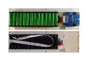
Battery Holder, 14 Cells, 18650 Size, Screw Mount
- Manufacturer: STMICROELECTRONICS
- Product type: Battery Holders
- SVHC: No SVHC (25-Jun-2025)
- Product Range: -
- No. of Batteries: 14
- Battery Holder Mount: Screw
- Battery Sizes Accepted: 18650
| Delivery and price | |
|---|---|
| Units per pack | 1 |
| Price | 243.42 € |
| Current stock | 10+ |
| Lead time | 30 days |
**AEK-POW-BMSHOLD**

Data brief

## Battery holder for cylindrical batteries and battery management system node for automotive applications

## **Features**

- 14-slot battery holder for cylindrical INR 18650 battery cells (not included)

- All batteries are connected in series

- Proper housing for the AEK-POW-BMS63EN, AEK-POW-BMSWTX, AEKPOW-BMSNOTX, AEK-POW-BMSCC and AEK-POW-BMSCCTX evaluation boards BMS node (not included)

- Easy battery removal supported by a satin ribbon

- Low-side current sensing through an external resistor included in the package a 100 mΩ, 10 W resistor

- Five NTC thermistors (included)

- Stackable kit to build a compact battery pack (mechanical parts included)

- Dimensions 425 x 120 x 52 mm

|||•<br>Low-side current sensing through an external resistor included in the package<br>a 100 mΩ, 10 W resistor<br>•<br>Five NTC thermistors (included)<br>•<br>Stackable kit to build a compact battery pack (mechanical parts included)<br>Dimensions 425 x 120 x 52 mm|
|---|---|---|
|**Product summary**<br>~~[7~~||•<br>Dimensions 425 x 120 x 52 mm<br>•<br>Included in theAutoDevKitecosystem|
|Battery holder for|||
|cylindrical batteries<br>and battery|AEK-POW-|**Description**|
|management system|BMSHOLD||
|node for automotive<br>applications||The battery management system (BMS) is a fast-growing application pervading<br>several fields of the electronic industry including automotive and industrial markets.|
|Automotive chip for<br>battery management<br>applications with daisy<br>chain up to 31 devices|L9963E|To support fast evaluation and meet stringent time-to-market for BMS solutions, the<br>AutoDevKit ecosystem has been extended to include a specific cylindrical battery<br>holder.|
|Battery management<br>system module based<br>on L9963E|AEK-POW-<br>BMS63EN|The purpose of this extension is to quickly create a battery pack to evaluate ST BMS<br>solution based on theAEK-POW-BMS63ENanalog front end node hosting the<br>L9963Eand theAEK-COM-ISOSPI1ISOSPI transceiver hosting theL9963T.|
|Battery management<br>system module based<br>on the L9963E and|AEK-POW-<br>BMSWTX|You can test the battery pack also using our latest BMS evaluation boards:AEK-<br>POW-BMSWTX,AEK-POW-BMSNOTX,AEK-POW-BMSCCandAEK-POW-<br>BMSCCTX.|
|L9963T||TheAEK-POW-BMSHOLDbattery holder contains a maximum of 14 cells, all|
|Non-isolated Battery<br>Management node|AEK-POW-<br>BMSNOTX|connected in series, and a dedicated slot and connector for our range of BMS<br>evaluation boards.|
|Optimized form-factor<br>and packaged battery<br>management system<br>module based on|AEK-POW-<br>BMSCC|To build a complete battery pack in both centralized or dual-ring topologies, you can<br>stack up to three / fourAEK-POW-BSMHOLDkits (the limit is the stackable weight).<br>A separate bag inside the kit package contains six M3x12 mm pan steel screws, four<br>M3x25 mm plus six M3x30 mm hexagonal steel spacers. These elements can be|
|L9963E for battery||used to mount anotherAEK-POW-BMSHOLDlayer.|
|pack easy mounting||TheAEK-POW-BMSHOLDhas a long satin ribbon tied to a buttonhole on the|
|Optimized form-factor||plexiglass used to support easy battery removal.|
|and packaged battery||The internal wiring of the featured 4-pole mammoth connector allows adding a|
|management system<br>module based on<br>L9963E and L9963T<br>for battery pack easy|AEK-POW-<br>BMSCCTX|sensing resistor between pin 2 and pin 3. Pin 1 and pin 4 are, respectively, the<br>positive and the negative terminals of the mockup. For demo purposes, a 100 mΩ, 10<br>W, ±1% precision resistor is included in the kit package.|
|mounting||TheAEK-POW-BMS63ENnode boards have to be connected to the crimped central|
|SPI to isolated SPI<br>dongle based on the<br>L9963T transceiver|AEK-COM-<br>ISOSPI1|connector provided in theAEK-POW-BMSHOLDkit.<br>The connector is organized as follows: pin 1 is the cell VBAT, pin 2 to 16 are<br>dedicated to the battery connections, pins 17 and 18 are ext Ground, pins 19 and 20|
|Automotive general<br>purpose SPI to|L9963T|are ISenseP and ISenseM, pins 21 to 30 are dedicated to NTCs for temperature<br>sensing.|


**DB5082** - **Rev 3** - **April 2025** For further information, contact your local STMicroelectronics sales office.

www.st.com

**AEK-POW-BMSHOLD**

|**Product summary**|**Product summary**|The even numbers with yellow cables are NTC-, whereas the odd numbers with blue<br>cables are NTC+. Five 10 kΩ, ±1% tolerance NTC thermistors are provided in the kit.<br>TheAEK-POW-BMSHOLDkit supports INR 18650 battery type. The estimation of<br>SoC and SoH included in AutoDevKit Studio is computed through an extended<br>kalman filter with characterization data coming from INR 18650 MJ1 batteries by LG.<br>_Note:_<br>_For further information on our range of BMS evaluation boards, refer_<br>_to the board related page onwww.st.com and toUM3185._|
|---|---|---|
|isolated SPI<br>transceiver|||
|AutoDevKit Studio for<br>32-bit power<br>architecture MCUs|STSW-<br>AUTODEVKIT||
|Application|Automotive<br>Battery<br>Management<br>System (BMS)||


**DB5082** - **Rev 3**

**page 2/10**

**AEK-POW-BMSHOLD Block diagram**

**1**

## **Block diagram**

**Figure 1. Block diagram**

**==> picture [3 x 14] intentionally omitted <==**

**----- Start of picture text -----**<br>
IsenseM<br>**----- End of picture text -----**<br>


The image above shows the block diagram of connections between the battery holder and the BMS evaluation board when using an AEK-POW-BMS63EN.

**DB5082** - **Rev 3**

**page 3/10**

**AEK-POW-BMSHOLD Block diagram**

**Figure 2. Stacked layers**

**DB5082** - **Rev 3**

**page 4/10**

**AEK-POW-BMSHOLD How to use the AEK-POW-BMSHOLD**

**2 How to use the AEK-POW-BMSHOLD**

**Step 1.** Connect the BMS evaluation board to the battery holder through the dedicated connector.

**Figure 3. BMS evaluation board connection to the battery holder**

**Step 2.** Use the screws included in the pack to anchor the board to the mockup.

**DB5082** - **Rev 3**

**page 5/10**

**AEK-POW-BMSHOLD**

**How to use the AEK-POW-BMSHOLD**

## **Step 3.** Place the batteries in the dedicated slot.

_Note:_

_The cell number goes from 1 to 14 (from the board downwards to the end of the mockup)._

_Important:_

_Pay attention to the polarity indicated on the plexiglass to avoid short-circuits. Place the satin ribbon under the batteries to remove them easily._

- **Step 4.** Optionally, you can use the flying cables to connect the NTCs included in the pack.

   - After connecting one or more NTCs to the positive and negative cables, you can place them on the batteries to sense the cell temperatures.

Cell voltage varies according to the external temperature variations. Voltages are indicated in the characterization curve of the component datasheet (Vishay, PN NTCALUG02A103F).

## **Figure 4. Cables to connect external NTCs**

**DB5082** - **Rev 3**

**page 6/10**

**AEK-POW-BMSHOLD How to use the AEK-POW-BMSHOLD**

**Step 5.** The battery holder could also be used to supply an external load, such as a motor, a lamp, LEDs, etc. For this scope, connect the resistor (included in the pack) to the mammoth connector. Then, connect the positive and negative cables to the load as indicated on the plexiglass.

**Figure 5. Connection scheme**

The maximum current allowed is 10 A. You could connect another resistor to absorb more current.

**DB5082** - **Rev 3**

**page 7/10**

**AEK-POW-BMSHOLD How to use the AEK-POW-BMSHOLD**

**Figure 6. Connecting the resistor to the mammoth connector**

**DB5082** - **Rev 3**

**page 8/10**

**AEK-POW-BMSHOLD**

## **Revision history**

## **Table 1. Document revision history**

|**Date**|**Revision**|**Changes**|
|---|---|---|
|11-Sep-2023|1|Initial release.|
|26-Sep-2024|2|Updated Features, Product Summary, Description, Section 1: Block diagram<br>and Section 2: How to use the AEK-POW-BMSHOLD.|
|17-Apr-2025|3|Updated Features, Product Summary and Description. Added references to<br>AEK-POW-BMSCC and AEK-POW-BMSCCTX.|


**DB5082** - **Rev 3**

**page 9/10**

**AEK-POW-BMSHOLD**

## **IMPORTANT NOTICE – READ CAREFULLY**

STMicroelectronics NV and its subsidiaries (“ST”) reserve the right to make changes, corrections, enhancements, modifications, and improvements to ST products and/or to this document at any time without notice. Purchasers should obtain the latest relevant information on ST products before placing orders. ST products are sold pursuant to ST’s terms and conditions of sale in place at the time of order acknowledgment.

Purchasers are solely responsible for the choice, selection, and use of ST products and ST assumes no liability for application assistance or the design of purchasers’ products.

No license, express or implied, to any intellectual property right is granted by ST herein.

Resale of ST products with provisions different from the information set forth herein shall void any warranty granted by ST for such product.

ST and the ST logo are trademarks of ST. For additional information about ST trademarks, refer to www.st.com/trademarks. All other product or service names are the property of their respective owners.

Information in this document supersedes and replaces information previously supplied in any prior versions of this document.

- © 2025 STMicroelectronics – All rights reserved

**DB5082** - **Rev 3**

**page 10/10**
Updated at April 24, 2026
STMicroelectronics is a global leader in the semiconductor industry, recognized for developing highly integrated, energy-efficient solutions that power modern electronics. With a strong focus on innovation, ST provides a comprehensive portfolio of microelectronics that address the demanding requirements of industrial, automotive, communications, and consumer applications. Our extensive selection of STMicroelectronics components is built around a robust lineup of discrete semiconductors and circuit protection devices. We offer a wide variety of single MOSFETs, Schottky diodes, and fast and ultrafast recovery rectifier diodes, designed to deliver exceptional efficiency and thermal performance in power management and conversion systems. For robust circuit protection, our inventory features hundreds of transient voltage suppressors and TVS diodes that safeguard sensitive electronic components against destructive voltage spikes. In addition to core power discretes like TRIACs, SCRs, bipolar transistors, and single IGBTs, our STMicroelectronics range includes specialized integrated passive filters and MEMS sensors. Furthermore, ST offers advanced integrated passive devices, such as baluns and RF filters, which utilize high-quality monolithic RF IPD processes on glass or high-resistance silicon substrates. These components provide competitive cost structures, reduced power losses, and simplified RFIC-to-antenna matching, ensuring optimal system performance and delivering the reliability required for next-generation wireless and power designs.
About Novapart
Novapart is a B2B electronic component broker specialising in stock shortages and cost reduction. We source hard-to-find parts and identify compliant alternatives across a catalogue of 410,000+ components from 500+ manufacturers.
Learn more →Stock Shortage Specialist
When a component is unavailable, discontinued or has an unacceptable lead time, we tap into our network of vetted European and Asian distributors to source what you need — without compromising on quality or traceability.
Request a quote →Compliant Alternatives
We identify pin-to-pin, electrically equivalent substitutes that meet the same certifications (RoHS, AEC-Q100, REACH) as your original specification — validated against datasheets, not just part numbers. Often at a lower cost.
BOM Analysis service →