
Image not available
Illustrative purposes only

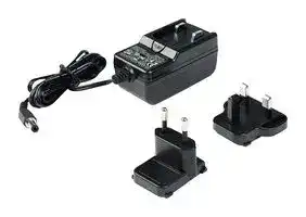
724-PSEU
AC/DC Power Supply, ITE, 1 Output, 24 VDC, 250 mA
⚠️ Reference pricing provided. In case of supply shortages, we will connect you with our trusted procurement partners to ensure your project's continuity.
- Manufacturer: SCS
- Product type: AC / DC External Plug In Adaptor Power Supplies
- Plug Type: Mains Plug Sold Separately
- No. of Outputs: 1 Output
- Output Connector: Barrel Plug Center Negative 2.1mm x 5.5mm x 9.5mm
- Input Voltage VAC: 100V AC to 240V AC
- Input Voltage AC Max: 240V
- Input Voltage AC Min: 100V
- Power Supply Approvals: ITE
- Power Supply Output Type: Fixed
- Output Current - Output 1: 250mA
- Output Voltage - Output 1: 24VDC
| Delivery and price | |
|---|---|
| Units per pack | 20 |
| Price | 27.44 € |
| Current stock | 10+ |
| Lead time | 30 days |
Datasheet

**USER GUIDE TB-9013**

## **724 Workstation Monitor Installation, Operation and Maintenance**

The following accessories are available for the 724 Workstation Monitor:

_Figure 1.  SCS 724 Workstation Monitor_

## **Description**

The SCS 724 Workstation Monitor is intended to monitor the operation of two wrist strap grounding systems and two worksurfaces.  This product has been designed and tested for use with SCS Dual ~~ee~~ -Wire Wrist Straps and Worksurface Mats.  If the equipment is used in a manner not specified in these instructions, the protection provided by the equipment may be impaired.  Use in any other application has not been evaluated by SCS and may lead to an unsafe condition.

The SCS 724 Workstation Monitor meets the requirements of ANSI/ESD S20.20 and recommendations of ESD Handbook ESD TR20.20 which includes “if the products that are being produced are of such value that knowledge of a continuous, reliable ground is needed, and then continuous monitoring should be considered or even required”.

The 724 Workstation Monitor is available in three models:

|**Item**|**Description**|
|---|---|
|724VK2|Verification Tester|
|724P<br>~~— lO~~|Verification Tester<br>Power Adapter, 120VAC Input, 25VDC<br>Output, North America Plug<br>~~lO~~|
|724-PSEU|Power Adapter, 100-240VAC Input,<br>24VDC Output, UK & Euro Plugs|
|732<br>~~a~~|Dual Operator Remote<br>~~ee~~|
|733<br>~~a ~~<br>~~a~~|Operator Remote<br> ~~ee~~<br>~~ee~~|
|770037<br>~~a ~~<br>~~a~~|Terminal Block, Pack of 5<br> ~~ee~~<br>~~ee~~|
|3057<br>~~a ~~<br>~~ee~~|StandbyJack<br> ~~ee~~<br>~~**ee**~~|
|2380D<br>~~ee~~<br>~~a~~|Mat Monitor Cord, with Diode, 6'<br>~~**ee**~~|


## **Packaging**

## **724 Workstation Monitor, North America**

- 1 724 Workstation Monitor

- 1 732 Dual Operator Remote

- 1 Dual Operator Remote Cable

- 1 Power Adapter, North America

- 1 Monitor Ground Cord

- 1 2380D Mat Monitor Cord

- 1 Two-Wire Terminal Block

- 2 Long Mounting Screws

- 2 Short Mounting Screws

- 2 Cable Tie Mounts

- 2 Zip Ties

- 1 Certificate of Calibration

|**Item**|**Description**|
|---|---|
|724|724 Workstation Monitor, North America|
|724MO|724 Workstation Monitor, No Power<br>Adapter|
|724K-WM11|724 Workstation Monitor Kit, with Wrist<br>Strapand Worksurface Mat|


_Figure 2.  SCS 724 Workstation Monitor packaging contents_

**SCS** - 926 JR Industrial Drive, Sanford, NC 27332 • (919) 718-0000 • Website: StaticControl.com

© 2016 DESCO INDUSTRIES, INC. Employee Owned

**TB-9013** Page 1 of 8 July 2016

## **724MO Workstation Monitor, No Power Adapter**

## **Features and Components**

- 1 724 Workstation Monitor

- 1 732 Dual Operator Remote

- 1 Dual Operator Remote Cable

- 1 Monitor Ground Cord

- 1 2380D Mat Monitor Cord

- 1 Two-Wire Terminal Block

- 2 Long Mounting Screws

- 2 Short Mounting Screws

- 2 Cable Tie Mounts

- 2 Zip Ties

- 1 Certificate of Calibration

**==> picture [187 x 8] intentionally omitted <==**

**----- Start of picture text -----**<br>
A B C D E F G H<br>**----- End of picture text -----**<br>


## **724K-WM11 Workstation Monitor Kit**

- 1 724 Workstation Monitor

_Figure 3.  SCS 724 Workstation Monitor features and components_

- 1 732 Dual Operator Remote

- 1 Dual Operator Remote Cable

- 1 Power Adapter, North America

- 1 Monitor Ground Cord

- 1 2380D Mat Monitor Cord

- 1 Two-Wire Terminal Block

- 2 Long Mounting Screws

- 2 Short Mounting Screws

- 2 Cable Tie Mounts

- 2 Zip Ties

- 1 2368 Elastic Dual-Wire Wristband

- 1 2360 Dual-Wire Wrist Cord

- 1 8811 Worksurface Mat Kit

- 1 Certificate of Calibration

## **Theory of Operation**

The SCS 724 Workstation Monitor is designed to monitor the operation of the wrist strap grounding systems of two operators. To accomplish this, it uses a DC current source to measure a loop electrical resistance.  The system uses a special wristband and wrist cord that contain two independent elements.  The 724 Workstation Monitor employs two selectable test voltages (9 and 16 volts) and resistance limits (10 Megohms and 35 Megohms).  It also monitors the grounding of one worksurface mat.  The Workstation Monitor contains a current-limiting resistor.  Resistance is monitored as the test voltage passes through one side of the wristband, through the skin of the wearer under the band, through the second side of the wristband, through the second conductor of the wrist cord that contains a current-limiting resistor, and finally back to the monitor.

- **A. Operator Remote Jack #1:** Connect the dual-wire wrist cord of operator #1 here to monitor their connection to ground.

- **B. Operator Remote Jack #2:** Connect the dual-wire wrist cord of operator #2 here to monitor their connection to ground.

- **C. Operator #1 Pass LED:** Illuminates green when operator #1 is properly grounded.

- **D. Operator #2 Pass LED:** Illuminates green when operator #2 is properly grounded.

- **E. Operator Fail High LED:** Illuminates red when either operator #1 or #2 fail high.  The buzzer will sound continuously when operator #1 is at fault, and it will sound intermittently when operator #2 is at fault.

- **F. Operator Fail Low LED:** Flashes yellow when either operator #1 or #2 fail low.

- **G. Worksurface Mat Fail LED:** Illuminates red and alarm sounds when the worksurface mat is not properly grounded.

- **H. Operator Test Limit and Test Voltage Switches:** The operator test limits may be set to either 10 megohms or 35 megohms, and the operator test voltage may be set to either 9V or 16V.  The additional ranges have been added to accommodate global electrical static discharge requirements. Selection of the operating parameters are left up to the user’s discretion.

NOTE: There is no power switch or power indication LED.  LEDs will illuminate once a wrist strap is connected to the operator remote.

_Figure 4.  Operator test limit and test voltage switches located on the right-side of the monitor_

**SCS** - 926 JR Industrial Drive, Sanford, NC 27332 • (919) 718-0000 • Website: StaticControl.com

© 2016 DESCO INDUSTRIES, INC. Employee Owned

**TB-9013** Page 2 of 8

## **OPERATOR MONITORING**

The wrist strap monitoring function is activated by plugging a wrist strap dual conductor ground cord into either one of the jacks on the SCS 732 or 733 Operator Remote.  If the resistance of the wrist strap loop is within the limits of the selected range (1.5 Megohms to 10 Megohms or 1.5 Megohms to 35 Megohms) on the Workstation Monitor, the cord, the wristband, and the contact to the arm of the wearer, it is considered to be functioning correctly.  At this time, one of the (OK) green LEDs (1 or 2) will be illuminated on the front of the monitor.

The wrist strap of the second operator is measured in the same way. Operators are identified by the two (OK) green LEDs (1 & 2).  However, the same high wrist strap red LED (H) and low yellow (L) LED illuminate when a fault is detected.  The green LED that extinguishes identifies the operator that is experiencing the fault condition.

If the resistance of the wrist strap loop is higher than the selected range (10 Megohms or 35 Megohms) on the Workstation Monitor, an (OK) wrist strap green LED (1 or 2) extinguishes, and a high wrist strap red LED (H) illuminates with an audible alarm.  This is an indication of a high resistance in the wristband, or poor contact between arm and band.  If the resistance in the loop is under 1.5 Megohms, it is an indication of a low resistance meaning one or both current-limiting resistors are bypassed.  The low yellow LED (L) will flash and an (OK) green LED (1 or 2) will remain illuminated.

|**Condition**|**9V-10**<br>**Megohms**|**Megohms**<br>**9V-35**<br>**Megohms**|**Megohms**<br>**16V-10**<br>**Megohms**|**16V-35**<br>**Megohms**|
|---|---|---|---|---|
|No Skin<br>Resistance|0.9V|0.9V|1.6V|1.6V|
|200K Ohm<br>Skin<br>Resistance|1.0V|1.0V|1.8V|1.8V|
|Likely Case<br>Before<br>Alarm|2.5V|3.6V|4.4V|6.4V|
|Worst Case<br>Before<br>Alarm|4.5V|7.1V|8.0V|12.6V|
|Absolute<br>Worst Case|9.0V|9.0V|16.0V|16.0V|


## **AUDIBLE ALARM SETTINGS**

For wrist strap malfunctions, the 724 Workstation Monitor indicates a different tone for each operator – a continuous tone for operator #1 and a fast chirping beep for operator #2.  The volume of the wrist strap alarm is adjusted by selection of the internal DIP switch 1.  For worksurface malfunctions, a slow chirping beep is made. This alarm sound is turned on or off by selection of DIP switch 2.  The DIP switches are accessible through a slot located on the bottom side of the monitor.

## **OPERATOR TEST VOLTAGE**

There is a concern about the voltage that is applied to an operator while they are connected to a monitor. Some of today’s electronic components are extremely sensitive to electrostatic discharge from a person (less than 10 volts).  The user should determine if these voltages can damage the device being handled. The following chart for the 724 Workstation Monitor illustrates the level of voltage that will appear on the operator under various resistance conditions.

A low resistance condition also can be caused by touching a grounded object or by standing on a conductive surface.  This may trigger the low resistance alarm on the 724 Workstation Monitor.

**==> picture [136 x 132] intentionally omitted <==**

**----- Start of picture text -----**<br>
LOUD MAT ALARM<br>ALARM ENABLE<br>SOFT MAT ALARM<br>ALARM DISABLE<br>**----- End of picture text -----**<br>


_Figure 5.  Audible alarm DIP switches located on the bottom side of the 724 Workstation Monitor_

**SCS** - 926 JR Industrial Drive, Sanford, NC 27332 • (919) 718-0000 • Website: StaticControl.com

© 2016 DESCO INDUSTRIES, INC. Employee Owned

**TB-9013** Page 3 of 8

## **WORKSURFACE MONITORING**

The 724 Workstation Monitor monitors its connection to ground and the grounding of a worksurface.  A loop resistance is measured from the monitor, through the mat monitor cord to the worksurface, across the conductive layer of the worksurface, through the grounding wire of the worksurface to an electrical ground and finally back to the monitor through the monitor's ground wire.  If the resistance of the loop exceeds 3.7 Megohms, the worksurface high red LED (M) will illuminate and all green LEDs will be extinguished.  If audible alarm DIP switch 2 is in the ON position (Figure 5), the audible alarm will activate.  If no ESD worksurface is to be monitored, the mat monitor cord and the ground wire of the 724 Workstation Monitor must be connected to an electrical ground.  This is done to ensure that the 724 Workstation Monitor is providing a ground connection for the operators.  Again, if the loop resistance exceeds 3.7 Megohms, the worksurface high red LED (M) will illuminate and the audible alarm will sound if enabled.

The ground wire from the worksurface and the ground wire from the 724 Workstation Monitor must be attached to separate electrical grounds.  The worksurface monitoring function is active whenever the monitor is powered.

Disconnect the mat monitor cord to prevent possible damage to the 724 Workstation Monitor before testing the resistance of the worksurface with a high voltage megohmmeter.

3. Connect the 724 Workstation Monitor to the 732 Dual Operator Remote using the included cable.

4. Determine the mounting location of the 732 Dual Operator Remote.  The front panel should be accessible to the operator(s).  Use the included long screws if desired.

5. Locate the black two-wire terminal block that is packaged with the monitor.  Use a small blade screwdriver to secure the mat monitor cord and ground cord to their respective terminals in the terminal block.

6. The 724 Workstation Monitor may be grounded using either its North American power adapter or the included green monitor ground cord.  See Figures 7 and 8.

**==> picture [238 x 115] intentionally omitted <==**

**----- Start of picture text -----**<br>
2380D Mat<br>Monitor Cord<br>Two-Wire<br>Terminal Block<br>Power Adapter<br>Ground Wire<br>2380D Mat<br>Monitor Cord<br>North American<br>Power Adapter<br>**----- End of picture text -----**<br>


## **Installation**

_Figure 7.  Using the North American power adapter to ground the 724 Workstation Monitor_

**==> picture [501 x 141] intentionally omitted <==**

**----- Start of picture text -----**<br>
724 Workstation Monitor<br>Power Adapter<br>2380D Mat<br>Monitor Cord<br>732 Dual<br>Operator Remote<br>Two-Wire<br>Mat Ground Cord Ground Terminal Block<br>(not included)<br>Green Monitor<br>Ground Wire<br>Connect the workbench<br>2380D Mat<br>terminal to ground when not  Monitor Cord<br>monitoring a worksurface Green Monitor<br>Ground Wire<br>Worksurface Mat<br>**----- End of picture text -----**<br>


_Figure 6.  Installing the 724 Workstation Monitor_

1. Remove the monitor from the carton and inspect for damage.

2. Determine the mounting location of the 724 Workstation Monitor.  The front panel should be visible to the operator(s).  Use the included short screws if desired.

_Figure 8.  Using the included green monitor ground cord to ground the 724 Workstation Monitor_

7. Plug the two-wire terminal block into the back of the 724 Workstation Monitor.

8. Route the mat monitor cord from the back of the monitor to the grounded worksurface mat.  Use the SCS 3034 or 3050 10mm Female Socket to secure the cord to the worksurface mat.

**SCS** - 926 JR Industrial Drive, Sanford, NC 27332 • (919) 718-0000 • Website: StaticControl.com

© 2016 DESCO INDUSTRIES, INC. Employee Owned

**TB-9013** Page 4 of 8

9. If using the monitor ground cord, attach its ring terminal to a ground point.  It is important that this ground cord is attached to a different ground point than that of the worksurface mat.  The face plate screw of a grounded AC wall outlet may provide a convenient connection point.

10. Connect the power adapter to the power jack located on the back of the monitor.  Route the wire from the supply to a nearby AC outlet, and plug it into the outlet.  Make sure the voltage and frequency match those listed on the power supply. The monitor is now powered.

NOTE: Worksurface must have a conductive layer. SCS continuous monitors are not recommended for use with homogeneous matting.

## **Operation**

## **USING THE MONITOR**

1. Fit the wristband snugly onto your wrist.

2. Connect the wrist cord to the wristband.

3. Plug the wrist cord into the monitored jack labeled “1” on the 732 Dual Operator Remote.  The corresponding operator LED will illuminate solid green on the 724 Workstation Monitor.  This indicates that the operator is properly grounded.

4. If this does not happen, examine the wrist cord for continuity or damage and your wristband to ensure that it fits securely.  If you have dry skin, apply an approved dissipative hand lotion such as Menda ™

Reztore ESD Hand Lotion.

## **FAULT CONDITIONS**

- **Red Wrist Strap LED (H) & Audible Alarm** This indicates that a high resistance condition (greater than 10 Megohms or 35 Megohms) exists for an operator or wrist strap assembly.  If two operators are connected to the monitor the high condition is with the operator whose green LED has extinguished.  Check the operator for good contact between the wrist and band.  Check the ground cord and connections for continuity.  Some operators have difficulty in providing sufficient continuity to the wristband due to dry skin or arm hair.  They may need to reposition the wristband on the arm or use an approved skin moisturizer such as ™

- Menda Reztore ESD Hand Lotion.

- **Yellow Wrist Strap LED (L) & No Audible Alarm** This indicates that a low resistance condition (less than 1.5 Megohms) exists between the operator and ground.  One or both of the one megohm current-limiting resistors are being bypassed.  A low resistance condition can be caused by touching a grounded object or by standing on a conductive surface.

- **Red Worksurface LED (M)** This indicates that a high resistance condition (> 3.7 Megohms) exists across the conductive layer of the worksurface and/or the ground connections.  Check the worksurface, ground cords and their connections for continuity.  Note the audible alarm may also sound if enabled.

## **SCS 3057 STANDBY JACK**

Since the activating switches are located in the SCS 732 and 733 Operator Remotes, the normal operating procedure is for the operators to disconnect their cords from the remotes when leaving the workstation. However, an optional Standby Jack that allows the wrist cord to remain plugged into the remotes is available.  Simply attach it to any convenient location then disconnect the cord from the wristband and connect it to the Standby Jack.  The green PASS LED on the 724 Workstation Monitor will illuminate upon connection.  The yellow FAIL LOW LED will slowly flash if the Standby Jack is grounded.  It can be grounded by attaching a ground wire to the screws or back plate. It can also be grounded if the plate is attached to a grounded metal surface.  The operator should reconnect the wrist cord to their wristband upon returning to the workstation.

_Figure 9.  Using the 724 Workstation Monitor_

**SCS** - 926 JR Industrial Drive, Sanford, NC 27332 • (919) 718-0000 • Website: StaticControl.com

© 2016 DESCO INDUSTRIES, INC. Employee Owned

**TB-9013** Page 5 of 8

## **Calibration**

Frequency of recalibration should be based on the critical nature of those ESD sensitive items handled and the risk of failure for the ESD protective equipment and materials.  In general, SCS recommends that calibration be performed annually.

Use the SCS 724VK2 Verification Tester to perform periodic testing (once every 6-12 months) of the 724 Workstation Monitor.  The Verification Tester can be used on the shop floor within a few minutes virtually eliminating downtime, verifying that the tester is operating within tolerances.

_Figure 10.  SCS 3057 Standby Jack_

See TB-9012 for more information.

## **SCS 733 OPERATOR REMOTE**

The SCS 733 Operator Remote is used to separate the two wrist strap jacks featured on the 732 Dual Operator Remote.  This provides a separation up to approximately 10 feet away from the 724 Workstation Monitor.  The 733 Operator Remote is to be used in conjuction with the 732 Dual Operator Remote that is supplied with the 724 Workstation Monitor.

See technical bulletin TB-9020 for installation instructions.

_Figure 11.  SCS 733 Operator Remote_

_Figure 12.  SCS 724VK2 Verification Tester_

**SCS** - 926 JR Industrial Drive, Sanford, NC 27332 • (919) 718-0000 • Website: StaticControl.com

© 2016 DESCO INDUSTRIES, INC. Employee Owned

**TB-9013** Page 6 of 8

## **Specifications**

## **Safety Information**

||**Workstation**<br>**Monitor**<br>**Dimensions**<br>**Operator Remote**<br>**Dimensions**<br>**Power Adapter**<br>**Requirements**<br>**(North American**|6.5" x 3.125" x 1.375"<br>(16.5 x 7.9 x 3.5 cm)<br>2.75" x 1.0" x 1.0"<br>(7.0 x 2.5 x 2.5 cm)<br>Input:<br>100-120 VAC<br>Output:<br>25 VDC @ 50 mA|**Warning**<br>To reduce the risks associated with fire and explosion:<br>•<br>Do not use in an explosive environment - monitor i<br>not designed to be intrinsically safe.<br>To reduce the risks associated with medical device<br>malfunction:<br>•<br>Persons with heart pacemaker devices should nev<br>use this monitor.|
|---|---|---|---|
||**power adapter**|50/60 Hz<br>rated load|To reduce the risks associated with hazardous voltage|
||**included)***||and fire:|
||**Output Plug**<br>**Polarization**|Center Negative|•<br>Use only the power supply provided by SCS and<br>specified for the country of use.|
||**Output Plug**<br>**Dimensions**|5.5 mm O.D. x 2.1 mm I.D. x 9.5<br>mm Length|•<br>Do not position the monitor accessories or other<br>equipment where unplugging the power supply is<br>difficult.|
||**Test Voltage**|9 VDC / 16 VDC Open circuit|•<br>Always locate the power source (socket or outlet)|
|||(Typical Value)|near the equipment. The power supply plug serves|
||**Test Current**|Less than 3 microamps (Typical<br>Value)|as the disconnect device.<br>•<br>Do not modify or attempt to service the power<br>supply or monitor; there are no user serviceable|
||**Environmental**|Indoor use only|parts.|
||**Operating**||•<br>Do not use the power supply if damaged.  Do not|
||**Conditions**||modify or attempt to service the power supply.|
||**Temperature**|Maximum:<br>110°F / 43°C<br>Minimum: 50°F /<br>10°C|Contact an SCS authorized service center for<br>replacement.|
||**Humidity**|Maximum relative humidity 80%<br>for temperatures up to 31°C to<br>50% relative humidityat 40°C.|•<br>Do not use the SCS Workstation Monitor or its<br>power supply outdoors in wet/humid environments.<br>•<br>Do not use the Workstation Monitor or its power<br>supply outside of the operating conditions listed in|
||_*SCS724-PSEU Po_|_wer Adater with UK / Euroe Plus_|<br>the user guide.|


- Do not use in an explosive environment - monitor is not designed to be intrinsically safe.

- Persons with heart pacemaker devices should never use this monitor.

- To reduce the risks associated with hazardous voltage and fire:

- Always locate the power source (socket or outlet) near the equipment. The power supply plug serves as the disconnect device.

_*SCS 724-PSEU Power Adapter with UK / Europe Plugs sold separately_

- Use only a dry cloth when cleaning.

## **Caution**

To reduce the risks associated with environmental contamination:

- Dispose of this monitor in accordance with all applicable local and government regulations.

## **Notice**

To reduce the risk of ESD damage to components or assemblies being handled:

- Monitor must be checked periodically to verify each test mode is functioning correctly.

- Ensure proper operation of monitor by performing operational verification test as required.

- Ensure tester is properly grounded.

**SCS** - 926 JR Industrial Drive, Sanford, NC 27332 • (919) 718-0000 • Website: StaticControl.com

© 2016 DESCO INDUSTRIES, INC. Employee Owned

**TB-9013** Page 7 of 8

## **Environmental Conditions**

This equipment has been tested and found to be safe to operate within these environmental conditions.  This is not a warranty of equipment performance within these conditions.

- Indoor use only

## **CE Statement**

Meets CE (European Confomity) requirements.

## **cULus Statement**

Meets UL Safety Requirements.

## **Made in China**

- Ingress Protection: IPX0

- Altitude: Up to 2,000m

- Mains supply voltage fluctuations up to ±10% of the nominal voltage.

- Transient overvoltage up to the levels of overvoltage category III.

- Temporary overvoltage occurring on mains supply.

- • Pollution degree 2.

**Limited Warranty, Warranty Exclusions, Limit of Liability and RMA Request Instructions** See the SCS Warranty - - http://staticcontrol.descoindustries.com/Limited Warranty.aspx

- Temperature: Maximum 110ºF / 43ºC Minimum 50ºF / 10ºC

- Humidity: Maximum relative humidity 80% for temperatures up to 31ºC decreasing linearly to 50% relative humidity at 40ºC.

## **FCC**

Note: This equipment has been tested and found to comply with the limits for a Class A digital device, pursuant to Part 15 of the FCC Rules. These limits are designed to provide a reasonable protection against harmful interference when the equipment is operated in a commercial environment. This equipment generates, uses, and can radiate radio frequency energy and, if not installed and used in accordance with the instruction manual, may cause harmful interference to radio communications. Operation of this equipment in a residential area is likely to cause harmful interference in which case the user will be required to correct the interference at their own expense.

Modifications to this device shall not be made without the written consent of SCS. Unauthorized modifications may void the authority granted under Federal Communication Rules and Industry Canada Rules permitting the operation of this device.

## **ICES Statement**

This Class A digital apparatus complies with Canadian ICES-003.

Cet appareil numérique de la classe A est conforme à la NMB-003 du Canada.

## **WEEE Statement**

The following information is only for EU-members States: The mark shown to the right is in compliance with Waste Electrical and Electronic Equipment Directive 2002/96/EC (WEEE). The mark indicates the requirement NOT to dispose the equipment as unsorted municipal waste, but use the return and collection systems according to local law.

**SCS** - 926 JR Industrial Drive, Sanford, NC 27332 • (919) 718-0000 • Website: StaticControl.com

© 2016 DESCO INDUSTRIES, INC. Employee Owned

**TB-9013** Page 8 of 8
Updated at February 9, 2023
About Novapart
Novapart is a B2B electronic component broker specialising in stock shortages and cost reduction. We source hard-to-find parts and identify compliant alternatives across a catalogue of 410,000+ components from 500+ manufacturers.
Learn more →Stock Shortage Specialist
When a component is unavailable, discontinued or has an unacceptable lead time, we tap into our network of vetted European and Asian distributors to source what you need — without compromising on quality or traceability.
Request a quote →Compliant Alternatives
We identify pin-to-pin, electrically equivalent substitutes that meet the same certifications (RoHS, AEC-Q100, REACH) as your original specification — validated against datasheets, not just part numbers. Often at a lower cost.
BOM Analysis service →