
Image not available
Illustrative purposes only

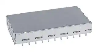
44-CBSA-1.0X1.5X0.4
EMI SHIELDING, 38.1 X 25.4 X 10.16MM
⚠️ Reference pricing provided. In case of supply shortages, we will connect you with our trusted procurement partners to ensure your project's continuity.
- Manufacturer: LEADER TECH-FERRISHIELD
- Product type: Shielding Gaskets & Material
- Product Range:40 CBS Series; Gasket Material:Tin Plated Steel; Length:38.1mm; Width:25.4mm; Depth:10.16mm; Attenuation:- 42AH0955
- SVHC: No SVHC (25-Jun-2025)
- Depth: 10.16mm
- Width: 25.4mm
- Length: 38.1mm
- Attenuation: -
- Product Depth: 10.16mm
- Product Range: 40 CBS Series
- Product Width: 25.4mm
- Product Length: 38.1mm
- Shielding Type: EMI Shielding
- Gasket Material: Tin Plated Steel
| Delivery and price | |
|---|---|
| Units per pack | 28 |
| Price | 23.01 € |
| Current stock | 10+ |
| Lead time | 30 days |
Datasheet

**CBS** Circuit board shielding 5 S t e p C o m m i t m e n t To O u r Va l u e d C u s t o m e r s ## 1. OUR VISION _(An aspiration worthy to strive for)_ We are committed to being the most reliable and innovative supplier in the EMI/ RFI industry, and as our name implies, the leader. In order to achieve this we will consistently strive to provide you with unparalleled service, innovation, and solutions. ## 2. OUR MISSION _(Our daily commitment to you)_ We are committed to consistently provide you with innovation and flexibility of design. Our engineering expertise and conscientious, outstanding customer service that will provide you with the right product, delivered on time. We are dedicated to making you look good to your customers. We want your repeat business. ## 3. OUR PRODUCTS _(Precision engineered to work in your application)_ - We are committed to product excellence. We offer our patented Circuit Board Shields (CBS), an extensive range of copper beryllium (CuBE), a Conductive Elastomer product line, TechVENT Honeycomb Panels, TechMESH knitted mesh, microwave absorbers, and FerriShield Ferrites. Using this diverse product line, Leader Tech is positioned to provide you with a ‘total shielding solution’ for all of your EMI/RFI shielding requirements. ## 4. OUR FACILITIES _(Continually expanding to meet your needs)_ - Leader Tech is committed to expansion wherever and whenever necessary. We are constantly expanding our hardware and software capabilities while investing in new equipment to manufacture and deliver the most precise and cost efficient shielding in the industry. Through the continuous support and backing of our parent company HEICO, the possibilities for new space and equipment are an ever-present reality. ## 5. OUR SERVICES _(Consistent reliability each time you order)_ We are committed to excellent service. Our staff undergoes a rigorous daily product, sales, and service training in order to serve you better. We want your calls answered by a person, not a machine, someone trained to qualify your needs and get answers to you when you need them. At Leader Tech we believe that the right people and the right equipment go hand in hand. **==> picture [105 x 42] intentionally omitted <==** **----- Start of picture text -----**<br> ISO 9001: 2008<br> CERTIFIED<br>✔ [RoHS] COMPLIANT<br>**----- End of picture text -----**<br> 2 Ta b l e o f C o n t e n t s |C B S C i r c u i t B o a r d S h i e l d i n g|C B S C i r c u i t B o a r d S h i e l d i n g| |---|---| |3<br>2<br>Intro to CBS<br>Shielding at the Source|| ||Se| |S t a n d a r d C B S|| |10 and 20 Series . . . . . . . .<br>40 Series . . . . . . . . . . . . . .<br>50 Series . . . . . . . . . . . . . .<br>80 Series . . . . . . . . . . . . .<br>KE Series . . . . . . . . . . . . . .<br>CBS2 . . . . . . . . . . . . . . . . .<br>Multi-Cavity CBS . . . . . . . .<br>CBS Engineering Notes . . .<br>4<br>6<br>8<br>10<br>12<br>14<br>16<br>_Shield heights from .130”_<br>_Shield heights from .400”_<br>_Shield heights from .500”_<br>_Shield heights from .800”_<br>_Offers alternate pin placement across various shield heights_<br>_Self-contained, 6-sided enclosure_<br>_Isolate multiple components in one shield_<br>_Technical specifications_<br>17|y<br>A| ||| ||| ||| ||| ||| ||———| ||| |M o d i f i e d C B S|| |15<br>Modified CBS . . . . . . . . . . .<br>_Near custom solutions without the cost_|ns)| |S l o t - L o k ™ S h i e l d s|| |18<br>20<br>21<br>19<br>Slot-Lok™ Standard . . . . .<br>Slot-Lok™. . . . . . . . . . . . .<br>Low Profile Slot-Lok™ . . .<br>Multi-Cavity Slot-Lok™ . . .<br>_Quick-Turn, Near-Custom Shielding_<br>_Enhanced Slot-Lok™ shielding variation_<br>_Shield heights less than .150”_<br>_Isolate multiple components in one shield_|—<br>‘~~—~~| ||~~—~~| ||| ||| |C u s t o m S h i e l d i n g|| |22<br>Custom Shielding . . . . . . .<br>_Unlimited design and production options_<br>~~A~~|~~A~~| |R e l a t e d Te c h n i c a l I n f o r m a t i o n|| |23<br>24<br>25<br>Packaging and Materials<br>Products and Literature<br>Global EMI Technology Center<br>CBS Part Number Builder<br>26|| ||| ||| ||a<br>ee| R e l a t e d Te c h n i c a l I n f o r m a t i o n 23 Packaging and Materials 24 Products and Literature 25 Global EMI Technology Center 26 CBS Part Number Builder 1 The Leading Edge in EMI Shielding Technology Circuit Board Shields (CBS) Using Standard Modular “off-the-shelf” Fence and Covers. ## _It’s Our Legacy!_ EMI designers demand extremely tight circuit board shields to prevent EMI/RFI radiation and susceptibility. This CBS Circuit Board Shielding Design Guide features multiple design variations of Leader Tech’s patented two-piece construction with a solderable fence and removable cover, considered by designers to have the strongest cover retention in the industry. It provides protection for sensitive components while allowing your technician access to adjust and repair. Leader Tech provides EMI designers flexibility and cost-effective custom solutions. This is achieved by stocking a large variety of standard “off-theshelf” fence options, which can be formed and combined with a cover to create a fully custom design. Additional features such as special cutouts, vent holes, insulating materials and other special requirements, can be added to create the right Circuit Board Shield for your application. Avoid long lead-times and expensive custom tooling by reviewing these EMI shielding innovations and selecting the right one for your next application. You will find that Leader Tech’s product diversity includes simple onepiece shields to more complicated multi-cavity shields using a variety of through-hole and surface mounting options. 2 Order Toll-Free 866.TECH.EMI (866.832.4364) Web LeaderTechInc.com ## Diverse board-level shielding solutions for all electronic applications ~~Lee~~ Leader Tech is not a one-product-fits-all company. We are innovators focused on constant improvement and refinement of proven product platforms and manufacturing methods. This allows us to deliver cost-effective shielding solutions that solve EMI problems for both current and emerging electronic applications. From small footprints and low-profile applications to multilevel board designs, we offer a wide selection of standard, modified standard and custom board level shielding products to fit your exact specifications. Four of the Leader Tech’s most popular product lines are described below. Additionally, the product comparison chart allows for “at-a-glance” comparisons of all design options. ## Multi-Cavity designs ## When space, weight and costs are all design priorities. Our flexible CBS and Slot Lok design and manufacturing processes allow engineers to effectively isolate multiple components using the same shield. The custom designed product typically incorporates multiple internal cavities that share connecting walls and a single cover. This allows for a reduction in shield weight and occupied board space. ## Slot-Lok™ Shields Po As close to custom as you can get…without the cost! Slot-Lok™ shields are designed and manufactured using proprietary methods that increase shield design flexibility while reducing lead time and total product cost. If you need a cost-effective shielding solution with near limitless design flexibility, Slot-Lok™ is the option of choice. ## Leader Tech Standard CBS ## Simply one of the best shields ever made. Our standard CBS products lead the board-level shielding industry in performance, flexibility and value. The highly reliable 2-piece design (fence and cover) accommodates virtually any through-hole or surface mount application. ## Custom shielding solutions Pe ## If you can describe it, we can manufacture it. Decades of engineering and manufacturing experience provide you with the ultimate board level shielding flexibility. From 3D modeling, material selection and prototyping to high volume production, we are with you every step of the way. ## Product Comparison Chart ||Ns|=|—<br>|SS|SS=.|=. aysoe|oe| |---|---|---|---|---|---|---| |PARAMETERS|STD. CBS|KE CBS|MODIFIED STD. SLOT-LOK|MODIFIED STD. SLOT-LOK™MULTI-CAVITY|MULTI-CAVITY|CUSTOM| |Through-Hole|Yes|Yes|Yes|Yes|Yes|Yes| |Surface Mount<br>~~Po~~|Yes|Yes|Yes|Yes|Yes|Yes| |Height Flexibility<br>~~es~~|0.13”-4.0”<br>~~GO~~|0.40”-2.0”<br>~~GO~~|0.13”-4.0”<br>~~GO~~|.080”-2.0”<br>~~GO~~|0.10”-2.0”<br>~~GO~~|from .080”<br>~~GO~~| |Design Flexibility<br>~~es~~<br>~~es~~|Good<br>~~GO~~<br>~~ee~~|Good<br>~~GO~~<br>~~es~~|VeryGood<br>~~GO~~|VeryGood<br>~~GO~~|VeryGood<br>~~GO~~|Excellent<br>~~GO~~<br>~~pe~~| |Material Flexibility<br>~~es~~<br>~~es~~|VeryGood<br>~~GO~~<br>~~ee~~|VeryGood<br>~~GO~~<br>~~es~~|VeryGood<br>~~GO~~|VeryGood<br>~~GO~~<br>~~po~~|VeryGood<br>~~GO~~<br>~~po~~|Excellent<br>~~GO~~<br>~~pe~~| |ShieldingEffectiveness<br>~~es ~~|Excellent<br> ~~ee~~|Excellent<br>~~es~~|Excellent|Excellent<br>~~po~~|Excellent<br>~~po~~|Excellent<br>~~pe~~| |Cover Retention<br>~~Pd~~<br>~~fp~~|Excellent|Excellent|Excellent|Very Good|Very Good<br>~~ee~~|Excellent<br>~~eee~~| |Tooling/NRE<br>~~fp~~|None<br>~~po~~|None<br>~~po~~|Low<br>~~po~~|Low<br>~~es~~|Low-Med<br>~~es~~<br>~~ee~~|Low-Med<br>~~es~~<br>~~eee~~| |Lead-Times<br>~~fppo~~|Excellent<br>~~a~~<br>~~po~~|Excellent<br>~~es~~<br>~~po~~|Excellent<br>~~es~~<br>~~po~~|Very Good<br>~~es~~|Very Good<br>~~es~~<br>~~ee ~~|Very Good<br>~~es~~<br> ~~eee~~| |RoHS Compliant<br>~~DO~~|Yes<br>~~DO~~|Yes<br>~~DO~~|Yes<br>~~DO~~|Yes<br>~~DO~~|Yes<br>~~DO~~|Yes<br>~~DO~~| 3 The Leading Edge in EMI Shielding Technology ## 10 - CBS Series |10 - CBS Series|10 - CBS Series|10 - CBS Series|10 - CBS Series|||Black = inches Red = mm|Black = inches Red = mm|Black = inches Red = mm| |---|---|---|---|---|---|---|---|---| ||||A||B|C||D| |STYLE|FIG.||HEIGHT|PIN SPACING|PIN SPACING|STANDOFFS|PIN LENGTH|PIN LENGTH| |10-CBS|1|.13|.13<br>(3,30)|none|none|none|none|none| |surface mount||||||||| |14-CBS|5|.13|.13<br>(3,30)|1.0|1.0<br>(25,4)|none|.05|.05<br>(1,27)| |14R-CBS|3|.13|.13<br>(3,30)|.50|.50<br>(12,7)|none|.10|.10<br>(2,54)| |14RA-CBS|3|.13|.13<br>(3,30)|.50|.50<br>(12,7)|none|.05|.05<br>(1,27)| |18R-CBS|3|.13|.13<br>(3,30)|.50|.50<br>(12,7)|none|.13|.13<br>(3,30)| ## 20- CBS Series ## Black = inches Red = mm |A<br>B<br>C<br>D<br>STYLE<br>FIG.<br>HEIGHT<br>PIN SPACING<br>STANDOFFS<br>PIN LENGTH<br>20-CBS<br>Black = inches Red = mm<br>20- CBS Series|A<br>B<br>C<br>D<br>STYLE<br>FIG.<br>HEIGHT<br>PIN SPACING<br>STANDOFFS<br>PIN LENGTH<br>20-CBS<br>Black = inches Red = mm<br>20- CBS Series|A<br>B<br>C<br>D<br>STYLE<br>FIG.<br>HEIGHT<br>PIN SPACING<br>STANDOFFS<br>PIN LENGTH<br>20-CBS<br>Black = inches Red = mm<br>20- CBS Series|A<br>B<br>C<br>D<br>STYLE<br>FIG.<br>HEIGHT<br>PIN SPACING<br>STANDOFFS<br>PIN LENGTH<br>20-CBS<br>Black = inches Red = mm<br>20- CBS Series|A<br>B<br>C<br>D<br>STYLE<br>FIG.<br>HEIGHT<br>PIN SPACING<br>STANDOFFS<br>PIN LENGTH<br>20-CBS<br>Black = inches Red = mm<br>20- CBS Series|A<br>B<br>C<br>D<br>STYLE<br>FIG.<br>HEIGHT<br>PIN SPACING<br>STANDOFFS<br>PIN LENGTH<br>20-CBS<br>Black = inches Red = mm<br>20- CBS Series| |---|---|---|---|---|---| |20-CBS<br>surface mount<br>20S-CBS<br>surface mount<br>21L-CBS<br>21M-CBS<br>21-CBS<br>22-CBS<br>23-CBS<br>24-CBS<br>24S-CBS<br>25-CBS<br>29-CBS<br>~~a~~<br>~~a ~~<br>~~a~~<br>~~a~~<br>~~a~~|1|.200<br>(5,08)|none|none|none| ||2<br>4<br>|.200<br>(5,08)<br>.225<br>(5,72)<br>|.50(12,7)<br> pad spacing<br>.50(12,7)|none<br>.025<br>(,63)|.21L(5,33)<br>.075W(1,90)<br>.15<br>(3,81)| ||4<br>4<br> ~~Gs~~|.225<br>(5,72)<br>.225<br>(5,72)<br>~~Gs~~|.50(12,7)<br>.50(12,7)|.025<br>(,63)<br>.025<br>(,63)|.13<br>(3,30)<br>.10<br>(2,54)| ||5|.200<br>(5,08)|1.0(25,4)|none|.10<br>(2,54)| ||4|.250<br>(6,35)|.50(12,7)|.050<br>(1,27)|.10<br>(2,54)| ||3|.200<br>(5,08)<br>~~ee~~|.50(12,7)<br>~~ee~~|none<br>~~ee~~|.10<br>(2,54)<br>~~ee~~| ||3|.200<br>(5,08)<br>~~ee ~~|.50(12,7)<br> ~~ee~~|none<br>~~ee~~|.05<br>(1,27)<br>~~ee~~| ||6|.225<br>(5,72)|1.0(25,4)|.025<br>(,63)|.10<br>(2,54)| ||3|.200<br>(5,08)|.50(12,7)|none|.13<br>(3,30)| **==> picture [83 x 7] intentionally omitted <==** **----- Start of picture text -----**<br> FIGURE 1 Surface Mount<br>**----- End of picture text -----**<br> **==> picture [160 x 8] intentionally omitted <==** **----- Start of picture text -----**<br> FIGURE 2 .50” Surface Mount Pad Spacing, No Standoff<br>**----- End of picture text -----**<br> **==> picture [126 x 243] intentionally omitted <==** **----- Start of picture text -----**<br> FIGURE 3 .50” Pin Spacing, No Standoff<br>FIGURE 4 .50” Pin Spacing, With Standoff<br>FIGURE 5 1.0” Pin Spacing, No Standoff<br>FIGURE 6 1.0” Pin Spacing, With Standoff<br>**----- End of picture text -----**<br> ## NOTES - Drawings in figures 1-6 are not to scale; see chart for sizing - Standard material .015” (,38) pre-tin plated steel - Other cover heights available, consult factory - Standard cover height: .115” (2,92) 10-CBS - .185” (4,70) 20-CBS 4 Order Toll-Free 866.TECH.EMI (866.832.4364) Web LeaderTechInc.com ## CBS 10 and 20 Series Configuration **==> picture [74 x 158] intentionally omitted <==** **----- Start of picture text -----**<br> COVER<br>HEIGHT<br>PIN<br>=,<br>WIDTH<br>.08’’<br>(2,03)<br>**----- End of picture text -----**<br> ## AVAILABLE HEIGHTS: 10 SERIES-.13” TO 2.0” (3,3 TO 50,8) 20 SERIES-.20” TO 2.0” (5,08 TO 50,8) Recommended hole size: .050” (1,27) ## Ventilation Patterns ## 10 and 20 Series Specs Sizes: .50” x .50” to 12” x 24” (.25” increments) Shapes: Squares, rectangles and odd shapes in .25” increments Heights: .13” to 2.00” Mounting Pins: .50” or 1.00” spacing Surface Mount: Available for all 10 and 20 series CBS Std Material: .015” (,38) pre-tin plated steel Cover Retention: 1.5 - 2.5 lb./linear inch Shielding Effectiveness: up to 60 dB ## Standard Options - Formed fence and cover - unassembled (F) - Assembled fence and cover (A) - Flat fence and formed cover (U) - Pre-tin plated Phos Bronze (P), Alloy 770 (N) - Ventilation holes (SV 15% or DV 30%) **==> picture [250 x 101] intentionally omitted <==** **----- Start of picture text -----**<br> SV PATTERN .156” HOLE » DV PATTERN .156” HOLE<br>9 (OXOXOTOTOLOROIO<br> oo7} FESS COCCCOOO<br>0-0-0-O 9° oF COCKOCOS<br>OOO aS OCOOCOOA<br>0 00 0 ,9% .0° OCCOCOOODG<br>0-0-0 an COCODOOS<br>0-0 0-0 50 O0O000000<br>an a S QOQ000OQ<br>.500” .250”<br>TYP TYP<br>**----- End of picture text -----**<br> Single density and double density ventilation holes available upon request. SV/DV (Standard) = .156” dia. SV2 /DV2 (Alternate) = .08” dia. ## Ordering a CBS is Easy 1. Select your style number - “21-CBS” 2. Choose standard options listed above - “21-CBSFNSV” 3. Specify your width in .25” increments from .50” to 12.00” - “21-CBSFNSV-2.5” 4. Specify your length in .25” increments from .50” to 24.00” - “21-CBSFNSV-2.5x4.5” 5. Specify your height from board to inside cover from .13” to 2.00” ” “21-CBSFNSV-2.5x4.5x.225 ## Mounting Hole Patterns (10 and 20 series) **==> picture [314 x 10] intentionally omitted <==** **----- Start of picture text -----**<br> 20S-CBS Foot Pattern .50 ” Pin Pattern<br>**----- End of picture text -----**<br> **==> picture [106 x 10] intentionally omitted <==** **----- Start of picture text -----**<br> 1.0 ” Pin Pattern<br>**----- End of picture text -----**<br> _Pin pattern viewed from top of shield. Consult factory for pin patterns for your application_ 5 The Leading Edge in EMI Shielding Technology |FIG.<br>~~eof tt~~|A<br>HEIGHT<br>~~tt~~|B<br>PIN SPACING<br>~~tt~~|C<br>STANDOFFS<br>~~tt~~|D<br>PIN LENGTH<br>~~tt~~| |---|---|---|---|---| |1<br>~~eof tt~~|.40<br>(10,16)<br>~~tt~~|none<br>~~tt~~|none<br>~~tt~~|none<br>~~tt~~| |3|.40<br>(10,16)|1.0<br>(25,4)|none|.12<br>(3,05)| |2|.40<br>(10,16)|.50<br>(12,7)|none|.12<br>(3,05)| |4<br>4|.40<br>(10,16)<br>.40<br>(10,16)|1.0<br>(25,4)<br>1.0<br>(25,4)|.010<br>(,25)<br>.010<br>(,25)|.12<br>(3,05)<br>.15<br>(3,81)| |4|.40<br>(10,16)|1.0<br>(25,4)|.010<br>(,25)|.15<br>(3,81)| |2|.40<br>(10,16)|.50<br>(12,7)|none|.15<br>(3,81)| |5|.40<br>(10,16)|.25<br>(6,35)|none|.12<br>(3,05)| |6|.40<br>(10,16)|.25<br>(6,35)|.005<br>(,13)|.12<br>(3,05)| FIGURE 1 Surface Mount **==> picture [117 x 81] intentionally omitted <==** **----- Start of picture text -----**<br> FIGURE 2 .50” Pin Spacing, No Standoff<br>FIGURE 3 1.0” Pin Spacing, No Standoff<br>**----- End of picture text -----**<br> ## NOTES - Drawings in figures 1-6 are not to scale; see chart for sizing - Standard cover height: .280” (7,11) 40-CBS **==> picture [121 x 8] intentionally omitted <==** **----- Start of picture text -----**<br> FIGURE 4 1.0” Pin Spacing, With Standoff<br>**----- End of picture text -----**<br> - Other cover heights available, consult factory FIGURE 5 .25” Pin Spacing, No Standoff FIGURE 6 .25” Pin Spacing, With Standoff 6 Order Toll-Free 866.TECH.EMI (866.832.4364) Web LeaderTechInc.com ## CBS 40 Series Configuration ## 40 Series Specs Sizes: .50” x .50” to 12” x 24” (.25” increments) Shapes: Squares, rectangles and odd shapes in .25” increments Heights: .40” to 3.00” **==> picture [306 x 78] intentionally omitted <==** **----- Start of picture text -----**<br> HEIGHT<br>AVAILABLE WITH<br>uy HEIGHT PINS FORMED FOR i<br>.050’’ SURFACE MOUNT<br>(1,27)<br>Z|<br>DIMPLES AVAILABLE UPON REQUEST DIMPLES AVAILABLE UPON REQUEST<br>**----- End of picture text -----**<br> Mounting Pins: .25”, .50” or 1.00” spacing Surface Mount: Available for all 40 series CBS Std Material: .015” (,38) pre-tin plated steel Cover Retention: 1.5 - 2.5 lb./linear inch Shielding Effectiveness: up to 60 dB ## Standard Options ## AVAILABLE HEIGHTS: 40 SERIES-.40” TO 2.0” (10,16 TO 50,5) Recommended hole size: .050” (1,27) - Formed fence and cover - unassembled (F) - Assembled fence and cover (A) - Flat fence and formed cover (U) - Pre-tin plated Phos Bronze (P), Alloy 770 (N) - Ventilation holes (SV 15% or DV 30%) **==> picture [242 x 123] intentionally omitted <==** **----- Start of picture text -----**<br> Ventilation Patterns<br>SV PATTERN .156” HOLE Q DV PATTERN .156” HOLE werererererer.<br>~ DOSSOOOG<br> Ooo | 9 ONS IOO000000,<br>0.0 0 O01 6° oF JOCCOOOOS}<br>oo o | ew JOCOCOOOOS}<br>0.0 0 Of [gS qs® JOOOOKOOA<br>00 oO | Reg8ha JOOCOCOO<br>0.0.0 oO! 50 exexexexexerere<br>nn oa S QO0000QQ<br>.500” .250”<br>TYP TYP<br>**----- End of picture text -----**<br> Single density and double density ventilation holes available upon request. SV/DV (Standard) = .156” dia. SV2 /DV2 (Alternate) = .08” dia. - Dimples for improved retention (D) - Ordering a CBS is Easy 1. Select your style number - “42-CBS” 2. Choose standard options listed above - “42-CBSFNSV” 3. Specify your width in .25” increments from .50” to 12.00” - “42-CBSFNSV-2.5” 4. Specify your length in .25” increments from .50” to 24.00” - “42-CBSFNSV-2.5x4.5” 5. Specify your height from board to inside cover from .40” to 2.00” ” “42-CBSFNSV-2.5x4.5x.40 **==> picture [238 x 13] intentionally omitted <==** **----- Start of picture text -----**<br> Mounting Hole Patterns (40 series)<br>**----- End of picture text -----**<br> **==> picture [477 x 10] intentionally omitted <==** **----- Start of picture text -----**<br> .25 ” ” Pin Pattern .50 ” Pin Pattern 1.0 ” Pin Pattern<br>**----- End of picture text -----**<br> _Pin pattern viewed from top of shield. Consult factory for pin patterns for your application_ 7 The Leading Edge in EMI Shielding Technology ## 50- CBS Series |FIG.|A<br>HEIGHT|B<br>PIN SPACING|C<br>STANDOFFS|D<br>PIN LENGTH| |---|---|---|---|---| |1|.50<br>(12,7)|none|none|none| |5|.50<br>(12,7)|1.0<br>(25,4)|.05<br>(1,27)|.12<br>(3,05)| |4|.50<br>(12,7)|1.0<br>(25,4)|none|.12<br>(3,05)| |4*|.50<br>(12,7)|1.0<br>(25,4)|none|.12<br>(3,05)| |3|.50<br>(12,7)|.50<br>(12,7)|.05<br>(1,27)|.12<br>(3,05)| |3|.50<br>(12,7)|.50<br>(12,7)|.05<br>(1,27)|.06<br>(1,53)| |2|.50<br>(12,7)|.50<br>(12,7)|none|.12<br>(3,05)| |5|.50<br>(12,7)|1.0<br>(25,4)|.01<br>(,250)|.12<br>(3,05)| |5<br>~~ee ee~~|.50<br>(12,7)<br>~~ee~~|1.0<br>(25,4)<br>~~es~~|.05<br>(1,27)|.15<br>(3,81)| |5<br> ~~ee ee~~|.50<br>(12,7)<br>~~ee~~|1.0<br>(25,4)<br>~~es~~|.01<br>(,250)|.15<br>(3,81)| |2|.50<br>(12,7)|.50<br>(12,7)|none|.15<br>(3,81)| |6|.50<br>(12,7)|.25<br>(6,35)|none|.12<br>(3,05)| FIGURE 1 Surface Mount FIGURE 2 .50” Pin Spacing, No Standoff FIGURE 3 .50” Pin Spacing, With Standoff FIGURE 4 1.0” Pin Spacing, No Standoff ## NOTES - Drawings in figures 1-6 are not to scale; see chart for sizing - Standard cover height: .280” (7,11) 50-CBS - Other cover heights available, consult factory - *52NN-CBS has no v-notches as depicted in fig. 4 FIGURE 5 1.0” Pin Spacing, With Standoff **==> picture [120 x 7] intentionally omitted <==** **----- Start of picture text -----**<br> FIGURE 6 .25” Pin Spacing, No Standoff<br>**----- End of picture text -----**<br> 8 Order Toll-Free 866.TECH.EMI (866.832.4364) Web LeaderTechInc.com **==> picture [184 x 12] intentionally omitted <==** **----- Start of picture text -----**<br> CBS 50 Series Configuration<br>**----- End of picture text -----**<br> ## 50 Series Specs Sizes: .50” x .50” to 12” x 24” (.25” increments) Shapes: Squares, Rectangles and Odd Shapes in .25” increments Heights: .50” to 3.00” **==> picture [305 x 79] intentionally omitted <==** **----- Start of picture text -----**<br> HEIGHT<br>) AVAILABLE WITH Y<br>HEIGHT PINS FORMED FOR<br>.050’’ y SURFACE MOUNT 4<br>(1,27)<br>Z|<br>DIMPLES AVAILABLE UPON REQUEST DIMPLES AVAILABLE UPON REQUEST<br>**----- End of picture text -----**<br> Mounting Pins: .25”, .50” or 1.00” spacing Surface Mount: Available for all 50 series CBS Std Material: .015” (,38) pre-tin plated steel Cover Retention: 1.5 - 2.5 lb./linear inch Shielding Effectiveness: up to 60 dB ## Standard Options ## AVAILABLE HEIGHTS: 50 SERIES-.50” TO 2.0” (12,7 TO 50,5) Recommended hole size: .050” (1,27) - Formed fence and cover - unassembled (F) - Assembled fence and cover (A) - Flat fence and formed cover (U) - Pre-tin plated Phos Bronze (P), Alloy 770 (N) - Ventilation holes (SV 15% or DV 30%) **==> picture [317 x 390] intentionally omitted <==** **----- Start of picture text -----**<br> Ventilation Patterns<br>SV PATTERN .156” HOLE Q DV PATTERN .156” HOLE a Sy<br>°° 00° D9) OXO> BGOO0OOOGO9000000 PesSS9G9Hs<br>0.00 0 SR OCOOOOCOCOO, RVGdeo¥f<br>0-0-O a o° COCOONS PHRGPoRe<br>000 0 598 98 CODOCOCOOKO, PRGSVSVG<br>0.0.0 S08 00 COCOOOOS) RQGSGHGH<br>0.0 © @ 50 O0000000 LG NGNG<br>S OOOCOC0OOO Ras<br>.500” .250”<br>TYP TYP<br>Single density and double density ventilation holes available upon request.<br>SV/DV (Standard) = .156” SV2 /DV2(Alternate) = .08”<br>Mounting Hole Patterns (50 series)<br>CaoooO [ene] ON<br>BYSHENY S 5 At<br>SNbob oboy bd en x<br>00 —_,-o-3-6-6-8 |) | |<br>000 —,-e—_s—*8<br>256-P\_ FENCE 9 256-0\ FENCE<br>906 —O ©<br>STARTS START<br>/56—-O o 756 —0<br>1.012 ——©-©@-©-8-© 1.012 -—_-e—e—6<br>.25 ” ” Pin Pattern .50 ” Pin Pattern<br>**----- End of picture text -----**<br> - Dimples for improved retention (D) - Ordering a CBS is Easy 1. Select your style number - “51-CBS” 2. Choose standard options listed above - “51-CBSFNSV” 3. Specify your width in .25” increments from .50” to 12.00” - “51-CBSFNSV-2.5” 4. Specify your length in .25” increments from .50” to 24.00” - “51-CBSFNSV-2.5x4.5” 5. Specify your height from board to inside cover from .50” to 2.00” ” “51-CBSFNSV-2.5x4.5x.50 **==> picture [106 x 10] intentionally omitted <==** **----- Start of picture text -----**<br> 1.0 ” Pin Pattern<br>**----- End of picture text -----**<br> _Pin pattern viewed from top of shield. Consult factory for pin patterns for your application_ 9 The Leading Edge in EMI Shielding Technology |FIG.|A<br>HEIGHT|B<br>PIN SPACING|C<br>STANDOFFS|D<br>PIN LENGTH| |---|---|---|---|---| |1<br>7|.80<br>(20,3)<br>.80<br>(203)|none<br>1.0<br>(254)|none<br>.05<br>(127)|none<br>.12<br>(305)| |7<br>5|.80<br>(20,3)<br>.80<br>(20,3)|1.0<br>(25,4)<br>1.0<br>(25,4)|.05<br>(1,27)<br> none|.12<br>(3,05)<br>.12<br>(3,05)| |6|.80<br>(20,3)|1.0<br>(25,4)|none|.12<br>(3,05)| |4|.80<br>(20,3)|.50<br>(12,7)|.05<br>(1,27)|.12<br>(3,05)| |4|.80<br>(20,3)|.50<br>(12,7)|.05<br>(1,27)|.06<br>(1,53)| |4<br>2|.80<br>(20,3)<br>.80<br>(20,3)|.50<br>(12,7)<br>.50<br>(12,7)|.05<br>(1,27)<br> none|.06<br>(1,53)<br>.12<br>(3,05)| |3|(20,3)<br>.80<br>(20,3)|(12,7)<br>.50<br>(12,7)|none|(3,05)<br>.12<br>(3,05)| |9|.80<br>(20,3)|.50<br>(12,7)|none|.12<br>(3,05)| |7|.80<br>(20,3)|1.0<br>(25,4)|.01<br>(,250)|.12<br>(3,05)| |7<br>~~ee~~|.80<br>(20,3)<br>~~ee~~|1.0<br>(25,4)|.05<br>(1,27)|.15<br>(3,81)| |7<br>~~ee~~|.80<br>(20,3)<br>~~ee~~|1.0<br>(25,4)|.01<br>(,250)|.15<br>(3,81)| |2<br> ~~ee~~|.80<br>(20,3)<br>~~ee~~|.50<br>(12,7)|none|.15<br>(3,81)| |8|.80<br>(20,3)|.25<br>(6,35)|none|.12<br>(3,05)| ## NOTES - Drawings in figures 1-9 are not to scale; see chart for sizing - Standard cover height .280” (7,11) 80-CBS - Other cover heights available, consult factory **==> picture [279 x 6] intentionally omitted <==** **----- Start of picture text -----**<br> FIGURE 8 .25” Pin Spacing, No Standoff FIGURE 9 .50” Pin Spacing, No Standoff<br>**----- End of picture text -----**<br> **==> picture [76 x 6] intentionally omitted <==** **----- Start of picture text -----**<br> FIGURE 1 Surface Mount<br>**----- End of picture text -----**<br> FIGURE 2 .50” Pin Spacing, No Standoff, With Holes FIGURE 3 .50” Pin Spacing, No Standoff, No Holes FIGURE 4 .50” Pin Spacing, With Standoff FIGURE 5 1.0” Pin Spacing, No Standoff, With Holes f J tL I ft L 5040 = D FIGURE 6 1.0” Pin Spacing, No Standoff, No Holes FIGURE 7 1.0” Pin Spacing, With Standoff, with holes 10 Order Toll-Free 866.TECH.EMI (866.832.4364) Web LeaderTechInc.com ## CBS 80 Series Configuration ## 80 Series Specs Sizes: .50” x .50” to 12” x 24” (.25” increments) Shapes: Squares, rectangles and odd shapes in .25” increments Heights: .80” to 4.00” **==> picture [306 x 78] intentionally omitted <==** **----- Start of picture text -----**<br> HEIGHT<br>AVAILABLE WITH<br>HEIGHT PINS FORMED FOR<br>.050’’ SURFACE MOUNT<br>(1,27)<br>Y<br>DIMPLES AVAILABLE UPON REQUEST DIMPLES AVAILABLE UPON REQUEST<br>**----- End of picture text -----**<br> Mounting Pins: .25”, .50” or 1.00” spacing Surface Mount: Available for all 80 series CBS Std Material: .015” (,38) pre-tin plated steel Cover Retention: 1.5 - 2.5 lb./linear inch Shielding Effectiveness: up to 60 dB ## Standard Options ## AVAILABLE HEIGHTS: 80 SERIES-.80” TO 2.0” (20,3 TO 50,5) Recommended hole size: .050” (1,27) - Formed fence and cover - unassembled (F) - Assembled fence and cover (A) - Flat fence and formed cover (U) - Pre-tin plated Phos Bronze (P), Alloy 770 (N) - Ventilation holes (SV 15% or DV 30%) **==> picture [250 x 132] intentionally omitted <==** **----- Start of picture text -----**<br> Ventilation Patterns<br>SV PATTERN .156” HOLE Q DV PATTERN .156” HOLE TOD OOO O(<br>"O00 | loo OSS 9090DOOO 00 00OD<br>0.0 0 0 imo° ANI OOOCODOA<br>oOo Oo | wR9 COCDDOOG<br>0 0 0 | ’egShia COOOOOOD)<br>0.0 0 oO! 9 © 00000000<br>S OCO000009O<br>.500” .250”<br>TYP TYP<br>**----- End of picture text -----**<br> Single density and double density ventilation holes available upon request. SV/DV (Standard) = .156” dia. SV2 /DV2 (Alternate) = .08” dia. - Dimples for improved retention (D) - Ordering a CBS is Easy 1. Select your style number - “81-CBS” 2. Choose standard options listed above - “81-CBSFNSV” 3. Specify your width in .25” increments from .50” to 12.00” - “81-CBSFNSV-2.5” 4. Specify your length in .25” increments from .50” to 24.00” - “81-CBSFNSV-2.5x4.5” 5. Specify your height from board to inside cover from .80” to 2.00” ” “81-CBSFNSV-2.5x4.5x.80 **==> picture [237 x 13] intentionally omitted <==** **----- Start of picture text -----**<br> Mounting Hole Patterns (80 series)<br>**----- End of picture text -----**<br> **==> picture [511 x 26] intentionally omitted <==** **----- Start of picture text -----**<br> .25 ” ” Pin Pattern .50 ” Pin Pattern 1.0 ” Pin Pattern<br>Pin pattern viewed from top of shield. Consult factory for pin patterns for your application<br>**----- End of picture text -----**<br> 11 The Leading Edge in EMI Shielding Technology ## CBS KE Series |FIG.|A<br>HEIGHT|B<br>PIN SPACING|C<br>NOTCH SIZE|D<br>PIN LENGTH| |---|---|---|---|---| |1|.40<br>(10,16)|(10,16)none|.03H<br>(0,76)<br>.06W<br>(1,52)|(0,76)none| |2|.40<br>(10,16)|.50<br>(12,7)|.03H<br>(0,76)<br>.06W<br>(1.52)|.12<br>(3,05)| |3|.40<br>(10,16)|.25<br>(6,35)|.03H<br>(0,76)<br>.06W<br>(1,52)|.12<br>(3,05)| |1<br>2|.50<br>(12,70)<br>.50<br>(12,70)|(12,70)none<br>.50<br>(12,7)|.03H<br>(0,76)<br>.06W<br>(1,52)<br>.03H<br>(0,76)|none<br>.12<br>(3,05)| |2<br>~~fff~~|.50<br>(12,70)<br>~~fff~~|.50<br>(12,7)<br>~~fff~~|.03H<br>(0,76)<br>.06W<br>(1,52)<br>~~fff~~|.12<br>(3,05)<br>~~fff~~| |3<br>~~fff~~|.50<br>(12,70)<br>~~fff~~|.25<br>(6,35)<br>~~fff~~|.03H<br>(0,76)<br>.06W<br>(1,52)<br>~~fff~~|.12<br>(3,05)<br>~~fff~~| |1<br>~~fff~~|.80<br>(20,32)<br>~~fff~~|(20,32)none<br>~~fff~~|(1,52)<br>.03H<br>(0,76)<br>.06W<br>(1,52)<br>~~fff~~|(0,76)none<br>~~fff~~| |2|.80<br>(20,32)|.50<br>(12,7)|.03H<br>(0,76)<br>.06W<br>(1,52)|.12<br>(3,05)| |3|.80<br>(20,32)|.25<br>(6,35)<br>|.03H<br>(0,76)<br>.06W<br>(1,52)|.12<br>(3,05)| FIGURE 1 Surface Mount **==> picture [84 x 87] intentionally omitted <==** **----- Start of picture text -----**<br> FIGURE 2 .50” Pin Spacing<br>FIGURE 3 .25” Pin Spacing<br>**----- End of picture text -----**<br> ## NOTES - Drawings in figures 1-3 are not to scale; see chart for sizing - Standard cover height: .280” (7,11) KE-CBS - Other cover heights available, consult factory 12 Order Toll-Free 866.TECH.EMI (866.832.4364) Web LeaderTechInc.com **==> picture [184 x 12] intentionally omitted <==** **----- Start of picture text -----**<br> CBS KE Series Configuration<br>**----- End of picture text -----**<br> ## KE Series Specs Sizes: .50” x .50” to 12” x 24” (.25” increments) Shapes: Squares, rectangles and odd shapes in .25” increments Heights: .40” to 2.00” **==> picture [306 x 78] intentionally omitted <==** **----- Start of picture text -----**<br> HEIGHT<br>AVAILABLE WITH<br>HEIGHT PINS FORMED FOR<br>.050’’ SURFACE MOUNT<br>(1,27)<br>Y<br>DIMPLES AVAILABLE UPON REQUEST DIMPLES AVAILABLE UPON REQUEST<br>**----- End of picture text -----**<br> Mounting Pins: .25”, .50” or 1.00” spacing Std Material: .015” (,38) pre-tin plated steel Cover Retention: 1.5 - 2.5 lb./linear inch Shielding Effectiveness: up to 60 dB ## Standard Options - Formed fence and cover - unassembled (F) ## AVAILABLE HEIGHTS: KE SERIES-.40” TO 2.0” (10,16 TO 50,8) Recommended hole size: .050” (1,27) - Assembled fence and cover (A) - Flat fence and formed cover (U) - Pre-tin plated Phos Bronze (P), Alloy 770 (N) - Ventilation holes (SV 15% or DV 30%) - Dimples for improved retention (D) **==> picture [246 x 126] intentionally omitted <==** **----- Start of picture text -----**<br> Ventilation Patterns<br>SV PATTERN .156” HOLE 9 Q ; BDOOCOOOG) DV PATTERN .156” HOLE YOOOOCOCOK<br> So oO | FBSSSS OO0O0000O0<br>oO Oo ae COOOCOOD)<br>ooo Bo 0° COOOCOOS<br>oo oo _ eee OCODDOOOT<br>oe oo Soe, CODODDCOG<br>oo oo 50 00000000<br>0 0 Y- C6 OCO0000OO<br>.500” .250”<br>TYP TYP<br>**----- End of picture text -----**<br> Single density and double density ventilation holes available upon request. SV/DV (Standard) = .156” dia. SV2 /DV2 (Alternate) = .08” dia. **==> picture [151 x 12] intentionally omitted <==** **----- Start of picture text -----**<br> Ordering a CBS is Easy<br>**----- End of picture text -----**<br> 1. Select your style number - “KE40-CBS” 2. Choose standard options listed above - “KE40-CBSFNSV” 3. Specify your width in .25” increments from .50” to 12.00” - “KE40-CBSFNSV-2.5” 4. Specify your length in .25” increments from .50” to 24.00” - “KE40-CBSFNSV-2.5x4.5” 5. Specify your height from board to inside cover from .40” to 2.00” ” “KE40-CBSFNSV-2.5x4.5x.40 **==> picture [453 x 216] intentionally omitted <==** **----- Start of picture text -----**<br> Mounting Hole Patterns (KE Series)<br>S<br>8383388 O<br>CaonnMaOomMn oO‘oO Oo 8BOo S<br>Fl |i<br>.0O0O0 —— f§-8-8-©-*©-© —— 950 . |<br>‘579 . 000 —Pp © o MP—<br>o ———<br>. 462 —¢. FENCE PT 200 FENCE<br>962— .» 66.06¢——— 1.012.800 an QD<br>| | | | | | 962 —D__6 =<br>NANNAANSN<br>—-oO-O-o © Ke) co<br>AFR ONS OO 0 19<br>.25 ” ” Pin Pattern .50 ” Pin Pattern<br>**----- End of picture text -----**<br> _Pin pattern viewed from top of shield. Consult factory for pin patterns for your application_ 13 The Leading Edge in EMI Shielding Technology |CBS2 Series|CBS2 Series|CBS2 Series|CBS2 Series||Black = inches Red = mm| |---|---|---|---|---|---| |STYLE||FIG.|A HEIGHT|PACKAGE HEIGHT|PACKAGE HEIGHT| |CBS2||1|.800(20,32)|.840 min. - 2.240 max|(21,36 min. - 56,90 max)| FIGURE 1 CBS2: Specific packaging heights and relative PCB locations are obtained by adjusting individual cover heights. NOTES: Drawing in Figure 1 is not to scale; see chart for sizing Engineered 6-sided Shield Enclosure CBS2 Series Specs The versatile 6-sided CBS2 Shielding Box can be mounted on any side or Material Options orientation. We recommend the use of GRIP-SERT style threaded inserts. • Pre-tin plated steel These inserts are completely threaded, enabling them to be utilized both as • Pre-tin plated Phos Bronze (P) a method of exterior box attachment and for PCB attachment inside of the • Mu metal shielding box. This allows the use of CBS2 shielding boxes in a wide variety of • Alloy 77 ~~0~~ unique mounting applications. Shapes These highly versatile inserts deliver high torque-out resistance and high pullout values in our standard .015’’ pre-tin plated steel or pre-tin plated Phos • Square Bronze (P). • Rectangle • L-shape • T-shape Design CBS2 Standoff Location The Leader Tech CBS2 consists of 0.250 Optional Features (TYP 4 PLCS) • I/O cutouts the following: 0.250 • (1) fence using proven cover (TYP 4 PLCS) O ~~G~~ • Mounting hardware for PCB retention fingers on both sides • Ventilation holes • (2) covers with height and INSIDE VIEW • Locking dimples features to be specified Standard Pattern ~~: -~~ 14 Order Toll-Free 866.TECH.EMI (866.832.4364) Web LeaderTechInc.com Leader Tech understands that not all shielding applications can be satisfied with a standard CBS product. We also recognize that target budgets do not always accommodate a custom shielding solution. The Leader Tech Modified CBS gives you the flexibility to customize a standard CBS shield with significant savings compared to custom alternatives. Our Modified CBS products use existing tooling and manufacturing processes to give you a near-custom shielding solution at a fraction of the cost. ## Modified CBS Specs ## Material Options - Alloy 770 ## Features/Benefits: - Short lead time - Pre-tin plated Phos Bronze - Pre-tin plated steel - Little or no NRE required (tooling cost) - Surface mount or through-hole design - Unrestricted perimeter sizes - Custom shapes to save space - rectangle, “T”, “L”, “Z” - Multi-cavity design flexibility - Multiple level design options ## Plating Options - Bright tin - Matte tin - Tin lead (not RoHS compliant) - Nickel - Strong cover retention using patented Leader Tech “fingers” - Removable cover for access to components - Grounding gaskets ## Height Options - .13” to 4.0” - I/O holes - Trace notches - Connector cutouts ## Through-hole Mounting Pins - .25”, .50” & 1.0” spacing - Enhanced shielding with RF absorbers - ESD protection with insulator padding 15 The Leading Edge in EMI Shielding Technology As the complexity of a board’s layout increases so does the need to maintain space, weight and cost control. To satisfy these demanding requirements, Leader Tech offers a cost-effective, multi-cavity version of its standard CBS product line. Our proprietary multi-cavity manufacturing process gives engineers the flexibility to isolate multiple board-level components using the same shield. The near-custom product uses “off-the-shelf” components to create multiple internal cavities that share connecting walls and a single cover. This allows for a significant reduction in shield weight and allocated board space while maintaining tight cost controls. ## Multi-Cavity Specs ## Material Options - Alloy 770 - Pre-tin plated Phos Bronze - Pre-tin plated steel In addition to unmatched performance, Leader Tech Multi-Cavity CBS shields also help reduce your final assembly cost and time-to-market. Our shields arrive ready to install for both through-hole and surface mount applications. ## Features/Benefits: - Proven multi-cavity performance - Minimal NRE ## Plating Options - Bright tin - Matte tin - Tin lead (not RoHS compliant) - Nickel - Short lead time - Nearly unlimited perimeter sizes - Surface mount or through-hole design ## Height Options - .13” to 2.0” - Mounting pins at .25”, .50” or 1.0” spacing - Shape possibilities- rectangle, “T”, “L”, “Z” - Strong cover retention using patented Leader Tech retention “fingers” - E-Z pull tabs for removal of cover and access to components - Multiple level shields - Welded partitions optional - Semi-custom shield using standard off-the-shelf features - Wide range of optional features based on CBS fences - Reduced cost alternative vs. machined housings - Consult factory for complete design assistance and engineering support 20S-CBS-2.0X3.0 X0.215 Order Toll-Free 866.TECH.EMI (866.832.4364) Web LeaderTechInc.com 16 |Overview|Part Number Checklist|Part Number Checklist| |---|---|---| |• The standard Leader Tech two-piece CBS consists of:<br>•(1) Fence- wave, reflow or hand soldered to the PCB<br>•(1) Cover- engages retention fingers on top edge of fence<br>• All dimensions are referenced from where the fence contacts the PCB|Height __________________________<br>Length __________________________<br>Width __________________________|| |• Actual dimensions can be obtained from pin location pattern including<br>material bend allowance (.006” per 90 degree corner in both X & Y axis)|Pin spacing<br>0.25”|0.50”| |• Recommended solder trace up to .100” wide|1.0”|no pins| |• It is advisable to verify pin location pattern with Leader Tech prior to<br>manufacture of PCB to assure lowest cost solution for production of your<br>Board Level Shield|Pin length<br>0.05”<br>0.12”|0.10”<br>0.13”| |• Pin location patterns provided on request for optimal PCB layout|0.15”|| |• Available Materials include:||| |•Pre-tin plated steel<br>•Phosphorous bronze<br>•Nickel silver alloy 770|Standoffs<br>0.005”<br>0.025”<br>Fence series|0.01”<br>0.05”| |• Custom shapes and multi-cavity layouts|10-20|40| |• Applications engineers are available for design assistance|50|80| ||KE|CBS2| |Minimum Heights for Each Fence Series|Material|| |• 10 SERIES = .130”(3,30)<br>• 20 SERIES = .200”(6,60)|Pre-tin plated steel<br>Pre-tin plated<br>Phos Bronze|Pre-tin plated steel<br>Alloy 770| |• 40 SERIES = .400”(10,16)||| |• 50 SERIES = .500”(12,70)|Plating|| |• 80 SERIES = .800”(20,32)<br>• Height is measured from the top of the PCB to the underside of the cover|Bright tin<br>Nickel|Matte tin<br>Tin lead| |• Standard heights from .130”(3,3) to 2.00”(50,8)|Ventilation holes|| |• By simply changing the cover height, any desired overall height is|Required|Not required| |achievable||| ||Notches|| ||Required|Not required| |Overall Catalog Dimensions for Length and Width||| |• Standard sizes from .500”(12,7) x .500”(12,7) to 12.00”(304,8) x<br>24.00” (609,6)|Access holes<br>Required|Not required| |• Minimum pin spacing of .250”(6,35) & minimum pad (surface mount)|Locking dimples|| |spacing .500”(12,7)|Required|Not required| |• Nominal catalog dimensions for length and width based on increments of<br>.250”(6,35).Example: 21- CBSF- 1.25” x 2.75” x .225”<br>• Other sizes available, please consult a sales engineer for modified|Multi-compartment<br>Required|Not required| |standard solutions||| |• All dimensions referenced here are nominal catalog dimensions||| _Call your Leader Tech Applications Engineer or reference our web site for technical updates: www.leadertechinc.com_ 17 The Leading Edge in EMI Shielding Technology ## Quick-Turn, Near Custom Shielding Solutions Slot-LokTM shields from Leader Tech represent a proprietary manufacturing process that increases shield design flexibility while reducing lead time and total product cost. Slot-LokTM Circuit Board Shields achieve this by applying standardized manufacturing methods to produce what would traditionally be a custom manufactured product. The proprietary Slot-LokTM manufacturing process has helped many companies reduce their design-to-delivery time by a factor of four without incurring tooling charges. ## A Slot-Lok™ Solution for any application eee Slot-Lok™ ............................................................p.18 Slot-Lok™ Pro .....................................................p.19 Low Profile Slot-Lok™ .........................................p.20 Multi-cavity Slot-lok™ .........................................p.21 An added feature of the Slot-LokTM design is an audible click that confirms secure retention of the cover. ## Slot-Lok[™] with Interlocking Corners **==> picture [256 x 147] intentionally omitted <==** **----- Start of picture text -----**<br> PICK SPOT<br>AS<br>PICK SPOT<br>INTERLOCKING CORNERS<br>EDP Se<br>INTERLOCKING CORNERS<br>**----- End of picture text -----**<br> - Lowest cost Slot-Lok™ design - Shortest lead time - Custom options available - Through-hole or surface mount - Locking & grounding dimples standard - Automated pick & place option - Tape & reel packaging option - RoHS compliant - Multiple finish plating options Interlocking “Corners 18 Order Toll-Free 866.TECH.EMI (866.832.4364) Web LeaderTechInc.com **==> picture [332 x 351] intentionally omitted <==** **----- Start of picture text -----**<br> bo Slot-Lok [™] Configuration<br>COVER<br>“a<br>FRAME FENCE<br>OO"<br>PCB<br>oD a<br>HEIGHT<br>PIN<br>1a.| dc<|<br>Lo Cutaway and Sideview<br>Cutaway Sideview<br>**----- End of picture text -----**<br> Slot-Lok[™] Series Specs Sizes: .50” x 12.00” Shapes: Squares, Rectangles and Odd Shapes Heights: <.150” to 2.00” Material Thickness: .010” (,25), .012” (,31) or .015” (,38) Std Material: Pre-tin plated steel Alloy 770 (Slok Lok™ Pro) Cover Retention: 1.5 - 2.5 lb./linear inch Shielding Effectiveness: up to 60 dB ## Standard Options - Unlimited board shield sizes - Limitless pin spacing options - Variety of cover retention methods - Pull tabs for ease of cover removal - Custom access holes and notches - Ventilation holes for cover - Multiple finish plating options ## Material Options - Pre-tin plated Phos Bronze - Brass - BeCu ## Finish Plating Options - Bright tin - Matte tin - Tin lead (not RoHS compliant) - Nickel **==> picture [332 x 18] intentionally omitted <==** **----- Start of picture text -----**<br> Slot-Lok [™] Pro with Welded Corners<br>bo<br>**----- End of picture text -----**<br> - No apertures for enhanced shielding performance - Solid wall construction with welded corner - Through-hole or surface mount - Unlimited flexibility in size and shape - Locking & grounding dimples standard - Highly customizable platform - Available in multi-cavity configurations - RoHS compliant Welded Corners 19 The Leading Edge in EMI Shielding Technology Leader Tech’s Low Profile Slot-Lok™ design is the perfect choice for demanding applications that require a board-level shield, but have a stringent height requirement of less than .150”. This design variation offers all of the flexibility and benefits of the standard Slot-Lok™ series with a very compact profile. The shields are manufactured using RoHS compliant materials which exhibit exceptional solder characteristics, corrosion resistance and shielding effectiveness. ## Low Profile Slot-Lok[™] Specs Sizes: .50” x 12.00” Shapes: Squares, Rectangles and Odd Shapes Heights: <.150” to 2.00” Material Thickness: .010” (,25), .012” (,31) or .015” (,38) Std Material: Pre-tin plated steel Cover Retention: 1.5 - 2.5 lb./linear inch Shielding Effectiveness: up to 60 dB ## Standard Options ## Low Profile Slot-Lok[™] Features and Benefits - Unlimited board shield sizes - Limitless pin spacing options - Low profile Slot-Lok™ design - Short lead time - Through-hole or surface mount - Tape and reel packaging for automatic placement available - Ideal for applications with height restrictions under .150” _Slots on frame to accommodate lower profile_ - Variety of cover retention methods - Pull tabs for ease of cover removal - Custom access holes and notches - Ventilation holes for cover - Multiple finish plating options ## Material Options - Pre-tin plated Phos Bronze - Alloy 770 - Brass - BeCu ## Finish Plating Options - Bright tin - Matte tin - Tin lead (not RoHS compliant) - Nickel 20 Order Toll-Free 866.TECH.EMI (866.832.4364) Web LeaderTechInc.com The proprietary and extremely cost-effective Slot-Lok™ design and manufacturing process can accommodate virtually any multi-cavity shielding application requirement. This circuit board shield uses a flexible manufacturing technology that increases design options while reducing lead time and total product cost. ## Multi-Cavity Slot Lok[™] Features and Benefits - Minimal NRE ## Multi-Cavity / Slot-Lok[™] Specs Sizes: .50” x 12.00” Shapes: Squares, Rectangles and Odd Shapes Heights: <.150” to 2.00” Material Thickness: .010” (,25), .012” (,31) or .015” (,38) Std Material: Alloy 770 Cover Retention: 1.5 - 2.5 lb./linear inch Shielding Effectiveness: up to 60 dB - Short lead time - Surface mount or through-hole design - Pin pitch matching - to replace existing “legacy” shields - E-Z pull tabs for ease of cover removal - Removable cover for access to components - Cover retention using standard locking and grounding dimples - Proven multi-cavity performance with interlocking corners - Multiple level shields ## Standard Options - Welded partitions - Mouse holes, notches, ventilation, standoffs - Welded fence assembly - Pick & place spot - Custom packaging: tape & reel, vacuum trays ## Material Options - Pre-tin plated Phos Bronze - Pre-tin plated steel ## Finish Plating Options - Bright tin - Matte tin - Tin lead (not RoHS compliant) - Nickel 21 The Leading Edge in EMI Shielding Technology **==> picture [303 x 14] intentionally omitted <==** **----- Start of picture text -----**<br> C u s t o m S h i e l d i n g Unlimited design and production options<br>**----- End of picture text -----**<br> ## The Ultimate Flexibility - Unlimited shapes & sizes Leader Tech is recognized as a world leader in the design and manufacturing of custom circuit board shields. Our comprehensive, consultative approach provides you with virtually limitless board-level shielding options. Our team involvement starts with your initial design concept and continues through 3D modeling, prototyping, testing, tooling and low- to high-volume manufacturing. We are pioneers in the development of new and innovative manufacturing techniques and processes. By relying on Leader Tech’s decades of experience, you can develop a custom shielding solution that is manufactured using proven, standardized methods- ultimately lowering your product cost while increasing your flexibility. - Unlimited material options - Unlimited plating options - Unlimited height- low to high - One or two piece design - Low volume prototype to high volume production - Welding - Soldering - Combination shields - Custom packaging - Embossing ## Leader Tech Benefits - Complete design assistance and 3D modeling services - Engineering assistance on existing “legacy” shields - Universal tooling and manufacturing experience - Cost containment options ISO 9001: 2008 CERTIFIED ✔[RoHS] COMPLIANT - Low- and high-volume product capabilities - Industry-best lead time - U.S-based manufacturing 20S-CBS-2.0X3.0 X0.215 22 Order Toll-Free 866.TECH.EMI (866.832.4364) Web LeaderTechInc.com All Leader Tech products are packaged and shipped direct from our Florida manufacturing facility. We hand pack all items to ensure the greatest product quality and the most economical shipping cost. - Hand-packed foam liners with inner cardboard reinforcement- at no extra charge Leader Tech can accommodate virtually any packaging request. Some of the most common packaging requests include: - Tape & Reel packaging - Vacuum tray • Customer-specified packaging - Bar coding on every package, including customer part - number Materials ~~Lo~~ Below is a list of the most common materials used by Leader Tech to manufacture standard, modified standard and custom circuit board shields. ## Tin Plated Steel - Most cost effective option - Most common material in PCB shielding - Stocked thicknesses .008, .010, .012 & .015” (other thickness available) ## Other Materials Upon Request - Copper - Brass - BeCu - Stainless steel - Bright tin and matte tin standard finish plating - Highly solderable ## Nickel Silver Alloy 770 - Copper based alloy - Common material used in PCB components - Stocked thicknesses .008”, .010”, .012” & .015” - Highly solderable - High corrosion resistance ## Phosphorous Bronze - Copper based alloy - Non-magnetic applications - Stocked thicknesses .010” & .015” - Pre-tin plated and unplated available ## Mu Metal - For use in low frequency applications - Non-magnetic applications 23 The Leading Edge in EMI Shielding Technology ## _Reliable Board, Enclosure and Cable Shielding Solutions_ Leader Tech is a world-leading innovator and US-based manufacturer of EMI shielding products for circuit boards, enclosures and cables. In addition to our best selling standard, modified standard and custom CBS shields, Leader Tech offers an expansive line of beryllium copper fingerstock gaskets, conductive elastomers, advanced RF absorber materials and EMI/RFI ferrites. **==> picture [169 x 24] intentionally omitted <==** **----- Start of picture text -----**<br> EMI FSG<br>EMI Enclosure FerriShield<br>Fabric Shielding<br>Solutions Catalog Ferrite Catalog<br>Gasket Catalog<br>**----- End of picture text -----**<br> ## LeaderTech Shielding Products ## Board Level Shielding - Standard and Multi-Cavity CBS - Modified Standard Options - Custom Circuit Board Shields ## Enclosure Shielding - BeCu Fingerstock Gaskets - TechSIL 5000 Conductive Elastomers - Conductive Fabric Shielding Gaskets - TechSIL 8000 Oriented Wire Gaskets ## FerriShield Ferrites - Snap-On Bisected & Solid Bead Ferrites - Round & Flat Styles for Cables, Wires and Flex Circuits - TechMESH Knitted Wire Gaskets - TechMESH Combo Strip & Gaskets - TechVent Honeycomb Shielding Panels - Low, High, Microwave and Wideband Frequency-Specific Material ## _EMI problem?_ _Our sales engineers are waiting for your call: 866-TECH-EMI (866-832-4364)_ _Visit our web site today to browse our complete product line, download literature and find your local sales engineer or sales representative! www.leadertechinc.com_ 24 Order Toll-Free 866.TECH.EMI (866.832.4364) Web LeaderTechInc.com Global EMI Shielding Technology Center Leader Tech’s Global EMI Shielding Technology Center located in Tampa, Florida is a one-of-a-kind, innovative manufacturing facility that delivers an unparalleled customer experience while satisfying growing demands for high-quality board, enclosure and cable shielding products. Every detail of our ultra-modern facility is tailor-engineered to streamline and improve our customer interaction, engineering and manufacturing processes. The Shielding Technology Center encompasses all facets of the business including people, building size and equipment to dramatically improve productivity and capacity across all of our EMI shielding product lines. From an enhanced engineering department to the optimized placement of every raw material and the deployment of custom designed manufacturing equipment, our facility is uniquely positioned to capture an ever-increasing share of the custom and semi-custom segment within the shielding market. In a time when companies are moving away from the EMI Shielding customer through offshore manufacturing and distribution channels, Leader Tech is committed to the US market by continuing to expand its industry experienced team, innovative manufacturing technology and US-based headquarters. As a core value of our company, Leader Tech believes that customers are better served when they are able to communicate directly with a live applications engineer instead of a machine or web site. Personalized and responsive support coupled with innovative domestic manufacturing have been and will continue to be the hallmark of Leader Tech’s industry-best engineering and customer support departments. ## ’ You re Invited... _Consider it an open invitation to visit!_ **==> picture [91 x 17] intentionally omitted <==** **----- Start of picture text -----**<br> ISO 9001: 2008<br> CERTIFIED<br>**----- End of picture text -----**<br> As a current or prospective Leader Tech customer you are invited to our beautiful Tampa, Florida headquarters for a personal tour of our facility and manufacturing capabilities. Please contact your regional sales engineer or our Tampa-based customer service department at 866.832.4364 or 813-855-6921. 25 The Leading Edge in EMI Shielding Technology ## **Leader Tech Modifiable Standard CBS Shields** Co Simply one of the best shields ever made. Our standard CBS products are at the top of the board-level shielding industry in performance, flexibility and value. The highly reliable 2-piece design (fence and cover) accommodates virtually any through-hole or surface mount application. ## CBS Features and Benefits - 3 – 5 Day Lead time - No tooling or NRE costs - ¼” increment shield length and width - Pin Spacing available in ¼”, ½”, 1” - .015 Tin plated steel - .015 Phosphor bronze Alloy 510 - .015 Nickel silver alloy 770 - Surface mount or through hole - Low Piece Price - Many sizes available with minimum heights as shown - 10 Series = .130” (3,30) - o 20 Series = .200” (6,60) o 40 Series = .400” (10,16) o 50 Series = .500” (12,70) o 80 Series = .800” (20,32) o KE Series = .400” (10,16) = .500” (12,70) = .800” (20,32) - Additional options available online ## **CBS Part Number Builder** **==> picture [557 x 310] intentionally omitted <==** **----- Start of picture text -----**<br> XX - CBS X X X X - XX x XX x XXX<br>Shield Shield<br>Select<br>a CBS Assembly Material Vent Hole Options Dimples Width Length Undercover<br>Options (.25” (.25” Height<br>Series #<br>increment) increment)<br>.015”<br>Formed No Vent No<br>Leave thick Tin Leave Leave<br>F Fence & Cover Holes Dimples<br>Blank Plated Blank Blank<br>Unassembled Steel Required Required<br>Dimples<br>.015”<br>Formed thick 0.156” Single Required<br>A Fence & Cover N SV Vent Hole D (40, 50,<br>Alloy<br>Assembled 770 Pattern (15%) 80, KE<br>.015” Series) i i " =] = | t<br>thick Tin 0.080”<br>Flat Fence &<br>U Formed Cover P Plated SV2 Single Vent<br>Phos. Hole Pattern<br>Bronze<br>0.118”<br>aS A<br>SV3 Single Vent<br>Hole Pattern ae re :<br>- > : of ‘ os<br>Part Number Examples Double Vent 0.156” a CS~ ~™ 7 sera 7 SSa0 £<br>DV<br>Hole Pattern 2 j Poa 0 eX @<br>Standard Example: (30%) N A a PoeZ orvw<br>54-CBSF-1.5x2.5x0.5<br>0.080”<br>a oe SE. Fy &<br>Example with DV2 Double Vent Z 4 “a ae ¢<br>Alloy770 & SV Vent Holes: Hole Pattern Me 7 LIK Caw<br>54-CBSFNSV-1.5x2.5x0.5 A Sd “4<br>0.118”<br>4 YZ As<br>DV3 Double Vent oS bf<br>Hole Pattern<br>**----- End of picture text -----**<br> 26 Order Toll-Free 866.TECH.EMI (866.832.4364) Web LeaderTechInc.com ## **CBS** eee Circuit board shielding L ✔[RoHS] COMPLIANT
Updated at June 9, 2026
About Novapart
Novapart is a B2B electronic component broker specialising in stock shortages and cost reduction. We source hard-to-find parts and identify compliant alternatives across a catalogue of 410,000+ components from 500+ manufacturers.
Learn more →Stock Shortage Specialist
When a component is unavailable, discontinued or has an unacceptable lead time, we tap into our network of vetted European and Asian distributors to source what you need — without compromising on quality or traceability.
Request a quote →Compliant Alternatives
We identify pin-to-pin, electrically equivalent substitutes that meet the same certifications (RoHS, AEC-Q100, REACH) as your original specification — validated against datasheets, not just part numbers. Often at a lower cost.
BOM Analysis service →