


2322252
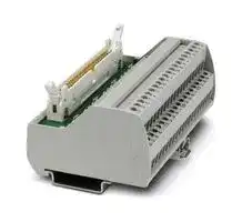
PASSIVE MODULE, 50POS, 24VDC, SCREW
- Manufacturer: PHOENIX CONTACT
- Product type: Controller Accessories
- SVHC: No SVHC (04-Feb-2026)
- Product Range: VARIOFACE VIP
- Current Rating: 1A
| Delivery and price | |
|---|---|
| Units per pack | 1 |
| Price | 112.62 € |
| Current stock | 10+ |
| Lead time | 30 days |
**RMW-L, RMF-L**

## Vishay Phoenix

## **Wirewound/Metal Film Resistors, Commercial Power, Radial Lead**

## **FEATURES**

- High power dissipation in small volume

- Low solder spot temperature

- Very stable mounting

- Non-flammable

- High pulse load handling capabilities

- High heat and moisture resistance

## **TECHNOLOGY**

**RMWL:** The resistive element is a wire which is wound on a fiber glass core. **RMFL:** The resistive element is a metal film resistor consisting of a metal layer deposited over a high grade ceramic rod. The mounting terminations are crimped to the resistive body to assure good mechanical and electrical contact. To ensure a flexible assembling process, the resistors are offered in various terminals styles, such as long or short, one or two pins in stainless steel for lower solder spot. The resistor body and lead ends are housed within a rectangular ceramic case which is non-flammable, will not melt even at high overloads and is resistant to most commonly used cleaning solvents, in accordance with IEC 60068-2-45.

|**STANDARD ELECTRICAL SPECIFICATIONS**|**STANDARD ELECTRICAL SPECIFICATIONS**|**STANDARD ELECTRICAL SPECIFICATIONS**|**STANDARD ELECTRICAL SPECIFICATIONS**|**STANDARD ELECTRICAL SPECIFICATIONS**|
|---|---|---|---|---|
|**MODEL**|**POWER RATING**<br>**_P_70 °C**<br>**W**|**RESISTANCE RANGE(1)**<br>Ω|**TOLERANCE(2)**<br>**%**|**E-SERIES**<br>**Decade**<br>**Values**|
|RMW03L|3|0.22 - 1.5<br>~~es~~|± 10<br>~~es~~|24|
|||1.6 - 3.9K<br>~~ee~~|± 5<br>~~ee~~||
|RMF03L||-<br>~~ee~~|± 10<br>~~ee~~||
|||100 - 39K<br>~~es~~|± 5<br>~~es~~||
|RMW05L|5|0.47 - 1.5<br>~~es~~|± 10<br>~~es~~||
|||1.6 - 4.7K<br>~~ee~~|± 5<br>~~ee~~||
|RMF05L||-<br>~~ee~~<br>~~ee~~|± 10<br>~~ee~~<br>~~ee~~||
|||100 - 51K<br>~~ee~~<br>~~ee~~|± 5<br>~~ee~~<br>~~ee~~||
|RMW07L|7|0.47 - 1.5<br>~~ee~~<br>~~ee~~|± 10<br>~~ee~~<br>~~ee~~||
|||1.6 - 7.5K<br>~~ee~~<br>~~ee~~|± 5<br>~~ee~~<br>~~ee~~||
|RMF07L||-<br>~~ee~~<br>~~ee~~|± 10<br>~~ee~~<br>~~ee~~||
|||1K - 100K<br>~~ee~~|± 5<br>~~ee~~||
|RMW10L|10|0.47 - 1.5<br>~~es~~|± 10<br>~~es~~||
|||1.6 - 10K<br>~~ee~~|± 5<br>~~ee~~||
|RMF10L||-<br>~~es~~|± 10<br>~~es~~||
|||1K - 150K<br>~~es~~|± 5<br>~~es~~||


## **Notes:**

- (1) Special resistance values available upon request

> (2) Other tolerances available upon request

**TECHNICAL SPECIFICATIONS PARAMETER UNIT RMWL RMF03L RMF05L RMF07L RMF10L** ~~fe es~~ Limiting Voltage V _P_ n x _R_ 750 1000 1200 1500 Insulation Voltage V > 2000 ~~G es P~~ R < 10 Ω : 0 to 600; Temperature Coefficient[ (3)] ppm/°C ± 250 R ≥ 10 Ω : - 80 to + 140; Operating Temperature °C - 25 to + 155 ~~a se~~ Short Time Overload - 10 x rated power for 5 seconds **Note:**

(3) Temperature Coefficient of ± 30, 50 or 90 ppm/ºC available on RMW upon request

For technical questions, contact: ww2aresistors@vishay.com

Document Number: 30251 Revision: 17-Oct-07

www.vishay.com 1

**RMW-L, RMF-L**

**==> picture [60 x 50] intentionally omitted <==**

## Wirewound/Metal Film Resistors, Commercial Power, Radial Lead

Vishay Phoenix

|**DIMENSIONS**|**DIMENSIONS**|**DIMENSIONS**|in millimeters(inches)|in millimeters(inches)|in millimeters(inches)||||||||||
|---|---|---|---|---|---|---|---|---|---|---|---|---|---|---|
||||P<br>L<br>W<br>W<br>H1<br>H2<br>R<br>e<br>f<br>c<br>H1<br>H2<br>h<br>i<br>j<br>k<br>g<br>R<br>**TERMINAL STYLE 1**<br>**(SINGLE PIN)**<br>**TERMINAL STYLE 2**<br>**(DOUBLE PIN)**|||c|W|||||W|||
||||||||||||||||
||||||||||||||||
||b|a|||||||||||||
||||||||||||||||
|||||||f|||||||||
|**TYPE**||||**L**|**P**|||**W**|||**H1**||**H2**||
|RMW03L<br>RMF03L||||24.0 ± 1.0<br>(0.95 ± 0.04)|12.5 ± 1.0<br>(0.49 ± 0.04)|||9.0 ± 1.0<br>(0.36 ± 0.04)|||9.0 ± 1.0<br>(0.36 ± 0.04)||10.0 ± 1.5<br>(0.40 ± 0.06)<br>or<br>25.0 ± 1.5<br>(0.99 ± 0.06)||
|RMW05L<br>RMF05L||||27.0 ± 1.0<br>(1.06 ± 0.04)|15.0 ± 1.0<br>(0.59 ± 0.04)|||9.5 ± 1.0<br>(0.38 ± 0.04)|||9.5 ± 1.0<br>(0.38 ± 0.04)||||
|RMW07L<br>RMF07L||||35.0 ± 1.0<br>(1.38 ± 0.04)|22.5 ± 1.0<br>(0.89 ± 0.04)|||9.5 ± 1.0<br>(0.38 ± 0.04)|||9.5 ± 1.0<br>(0.38 ± 0.04)||||
|RMW10L<br>RMF10L||||48.0 ± 1.0<br>(1.89 ± 0.04)|35.0 ± 1.0<br>(1.38 ± 0.04)|||9.5 ± 1.0<br>(0.38 ± 0.04)|||9.5 ± 1.0<br>(0.38 ± 0.04)||||


|**OTHER DIMENSIONS**in millimeters(inches)|**OTHER DIMENSIONS**in millimeters(inches)|**OTHER DIMENSIONS**in millimeters(inches)|**OTHER DIMENSIONS**in millimeters(inches)|
|---|---|---|---|
|**a**|0.4 ± 0.02 (0.02 ± 0.008)|**g**|7.3 ± 0.30 (0.29 ± 0.012)|
|**b**|5.0 ± 0.50 (0.20 ± 0.020)|**h**|1.5 ± 0.10 (0.06 ± 0.004)|
|**c**|7.3 ± 0.30 (0.29 ± 0.012)|**i**|1.4 ± 0.10 (0.06 ± 0.004)|
|**d**|1.5 ± 0.10 (0.06 ± 0.004)|**j**|5.0 ± 0.10 (0.20 ± 0.004)|
|**e**|1.4 ± 0.10 (0.06 ± 0.004)|**k**|4.5 ± 0.20 (0.80 ± 0.008)|
|**f**|4.5 ± 0.20 (0.18 ± 0.008)|||


## **ELECTRICAL CHARACTERISTICS**

The power that the resistor can dissipate depends on the operating temperature.

**==> picture [238 x 140] intentionally omitted <==**

**----- Start of picture text -----**<br>
100<br>0- 25 0 50 70 100 155 200<br>Tamb (°C)<br> (%)<br>max<br>P<br>**----- End of picture text -----**<br>


## **DERATING**

Maximum dissipation (Pmax) in percentage of rated power as a function of ambient temperature (Tamb)

For technical questions, contact: ww2aresistors@vishay.com

www.vishay.com

Document Number: 30251 Revision: 17-Oct-07

2

**RMW-L, RMF-L**

Wirewound/Metal Film Resistors, Commercial Power, Radial Lead

## Vishay Phoenix

**==> picture [59 x 50] intentionally omitted <==**

## **APPLICATION INFORMATION**

The temperature rise of terminal (solder spot) and resistor body (hot spot) as a function of load for terminal styles 1 and 2.

**==> picture [110 x 94] intentionally omitted <==**

**----- Start of picture text -----**<br>
Style 1 Style 2<br>Measuring point<br>**----- End of picture text -----**<br>


## **TERMINAL STYLE 1 (ONE PIN)**

## **SOLDER SPOT**

**==> picture [499 x 146] intentionally omitted <==**

**----- Start of picture text -----**<br>
70 30<br>H = 10 mm 10 W H = 25 mm<br>60 7 W 25 10 W<br>5 W 7 W<br>50<br>20 5 W<br>40 3 W<br>15<br>30 3 W<br>10<br>20<br>10 5<br>0 0<br>0 20 40 60 80 100 120 140 0 20 40 60 80 100 120 140<br>Load factor (%) Load factor (%)<br>T (°C) T (°C)<br>Δ Δ<br>**----- End of picture text -----**<br>


## **HOT SPOT**

**==> picture [232 x 146] intentionally omitted <==**

**----- Start of picture text -----**<br>
300<br>H = 10 mm<br>10 W<br>250<br>7 W<br>200 5 W<br>150<br>3 W<br>100<br>50<br>0<br>0 20 40 60 80 100 120 140<br>Load factor (%)<br>T (°C)<br>Δ<br>**----- End of picture text -----**<br>


**==> picture [232 x 146] intentionally omitted <==**

**----- Start of picture text -----**<br>
300<br>H = 25 mm<br>250 10 W<br>7 W<br>200 5 W<br>150<br>3 W<br>100<br>50<br>0<br>0 20 40 60 80 100 120 140<br>Load factor (%)<br>T (°C)<br>Δ<br>**----- End of picture text -----**<br>


For technical questions, contact: ww2aresistors@vishay.com

Document Number: 30251 Revision: 17-Oct-07

www.vishay.com 3

**RMW-L, RMF-L**

**==> picture [60 x 50] intentionally omitted <==**

## Wirewound/Metal Film Resistors, Commercial Power, Radial Lead

## Vishay Phoenix

## **TERMINAL STYLE 2 (TWO PINS)**

## **SOLDER SPOT**

**==> picture [232 x 147] intentionally omitted <==**

**----- Start of picture text -----**<br>
80<br>H = 25 mm<br>60 10 W<br>7 W<br>5 W<br>40<br>3 W<br>20<br>0<br>0 20 40 60 80 100 120 140<br>Load factor (%)<br>T (°C)<br>Δ<br>**----- End of picture text -----**<br>


## **HOT SPOT**

**==> picture [232 x 146] intentionally omitted <==**

**----- Start of picture text -----**<br>
300<br>H = 10 mm<br>10 W<br>250<br>7 W<br>200 5 W<br>150<br>3 W<br>100<br>50<br>0<br>0 20 40 60 80 100 120 140<br>Load factor (%)<br>T (°C)<br>Δ<br>**----- End of picture text -----**<br>


**==> picture [232 x 340] intentionally omitted <==**

**----- Start of picture text -----**<br>
25<br>10 W<br>H = 25 mm<br>20 7 W<br>5 W<br>15<br>3 W<br>10<br>5<br>0<br>0 20 40 60 80 100 120 140<br>Load factor (%)<br>300<br>H = 25 mm<br>250 10 W<br>7 W<br>200 5 W<br>150<br>3 W<br>100<br>50<br>0<br>0 20 40 60 80 100 120 140<br>Load factor (%)<br>T (°C)<br>Δ<br>T (°C)<br>Δ<br>**----- End of picture text -----**<br>


## **Notes:**

Application information available on request:

- Pulse load behavior

- High frequency behavior (self inductance)

## **MARKING**

The resistor is marked with the its type designation. The nominal resistance, the tolerance, the rated dissipation at Tamb = 70 °C and the production date (week and year), are printed in red on the resistor body. For values up to 910 Ω the R is used as a decimal point. For values of 1000 Ω or higher the letter K is used a decimal point.

## Example:

|PHX|RMW07L|7 W|
|---|---|---|
|2R2|5 %|221|


For technical questions, contact: ww2aresistors@vishay.com

www.vishay.com

Document Number: 30251 Revision: 17-Oct-07

4

**RMW-L, RMF-L**

## Vishay Phoenix

## Wirewound/Metal Film Resistors, Commercial Power, Radial Lead

**==> picture [59 x 50] intentionally omitted <==**

## **ORDERING CODE NUMBER**

The ordering code is indicating resistor type style/length of terminal and ohmic value.

|**ORDERING CODE NUMBER**|**ORDERING CODE NUMBER**|**ORDERING CODE NUMBER**|**ORDERING CODE NUMBER**|**ORDERING CODE NUMBER**|**ORDERING CODE NUMBER**|**ORDERING CODE NUMBER**|**ORDERING CODE NUMBER**|**ORDERING CODE NUMBER**|**ORDERING CODE NUMBER**|
|---|---|---|---|---|---|---|---|---|---|
|The ordering code is indicating resistor type style/length of terminal and ohmic value.||||||||||
||2<br>3<br>2||2<br>2|5<br>x|x<br>x|x<br>x<br>x<br>**OHMIC**<br>**VALUE**<br>**RESISTANCE**<br>**DECADE**<br>**LAST**<br>**DIGIT**<br>0.22Ω- 0.91Ω<br>7<br>1Ω- 9.1Ω<br>8<br>10Ω- 91Ω<br>9<br>100Ω- 910Ω<br>1<br>1 kΩ- 9.1 kΩ<br>2<br>10 kΩ- 91 kΩ<br>3<br>100 kΩ- 150 kΩ<br>4||||
|||||||||||
|||||||||||
|||||||||||
|**PRODUCT**<br>**TYPE**|**CODE**|**TYPE OF**<br>**TERMINAL**|**CODE**|**TERMINAL**<br>**LENGTH**|**CODE**||**OHMIC**<br>**VALUE**|**RESISTANCE**<br>**DECADE**|**LAST**<br>**DIGIT**|
|RMW03L<br>RMW05L<br>RMW07L<br>RMW10L<br>RMF03L<br>RMF05L<br>RMF07L<br>RMF10L|0<br>1<br>2<br>3<br>6<br>7<br>8<br>9|Style 1<br>Style 2|3<br>4|10.0 mm<br>(0.40")<br>25.0 mm<br>(0.98")|1<br>2|||0.22Ω- 0.91Ω<br>1Ω- 9.1Ω<br>10Ω- 91Ω<br>100Ω- 910Ω<br>1 kΩ- 9.1 kΩ<br>10 kΩ- 91 kΩ<br>100 kΩ- 150 kΩ|7<br>8<br>9<br>1<br>2<br>3<br>4|
|||||||||||
|||||||||||
|||||||||||


|**NAFTA ORDERING CODE NUMBER**|**NAFTA ORDERING CODE NUMBER**|**NAFTA ORDERING CODE NUMBER**|**NAFTA ORDERING CODE NUMBER**|**NAFTA ORDERING CODE NUMBER**|**NAFTA ORDERING CODE NUMBER**|**NAFTA ORDERING CODE NUMBER**|**NAFTA ORDERING CODE NUMBER**|||||||||
|---|---|---|---|---|---|---|---|---|---|---|---|---|---|---|---|
|The resistor have on ordering code with 18 digits, first<br>tolerance and terminal style.<br>R<br>M<br>W<br>0<br>5<br>W<br>4<br>**PRODUCT**<br>**TYPES**<br>**POWER**<br>**CODE**<br>**VALUE**<br>**5 DIGITS**<br>RMW<br>or<br>RMF<br>3 W<br>03W<br>1Ω<br>1R000<br>5 W<br>05W<br>10Ω<br>10R00<br>7 W<br>07W<br>100Ω<br>100R0<br>10 W<br>10W<br>1 kΩ<br>1K000<br>10 kΩ<br>10K00<br>100 kΩ<br>100K0|||||||first<br>4|5 digits for product type and the subsequent digits indicate the resistance value,<br>7<br>R<br>0<br>0<br>J<br>2<br>5<br>S<br>2<br>S<br>S<br>**TOLERANCES**<br>**CODE**<br>**TERMINAL**<br>**STYLES FOR**<br>**3 W UP TO 10 W**<br>**CODE**<br>**TERMINAL**<br>**STAINLESS**<br>**STEEL**<br>**CODE**<br>10 %<br>K<br>Terminal height<br>10 mm (0.394")<br>one pin<br>10S1<br>SS<br>5 %<br>J<br>Terminal height<br>10 mm (0.394")<br>two pins<br>10S2<br>Terminal height<br>25 mm (0.984")<br>one pin<br>25S1<br>Terminal height<br>25 mm (0.984")<br>two pins<br>25S2||||||||
|||||||||||||||||
|||||||||||||||||
|||||||||||||||||
|**PRODUCT**<br>**TYPES**|||**POWER**|**CODE**|**VALUE**|**5 DIGITS**||**TOLERANCES**||**CODE**|**TERMINAL**<br>**STYLES FOR**<br>**3 W UP TO 10 W**|**CODE**|**TERMINAL**<br>**STAINLESS**<br>**STEEL**||**CODE**|
|RMW<br>or<br>RMF|||3 W<br>5 W<br>7 W<br>10 W|03W<br>05W<br>07W<br>10W|1Ω<br>10Ω<br>100Ω<br>1 kΩ<br>10 kΩ<br>100 kΩ|1R000<br>10R00<br>100R0<br>1K000<br>10K00<br>100K0||10 %<br>5 %||K<br>J|Terminal height<br>10 mm (0.394")<br>one pin<br>Terminal height<br>10 mm (0.394")<br>two pins<br>Terminal height<br>25 mm (0.984")<br>one pin<br>Terminal height<br>25 mm (0.984")<br>two pins|10S1<br>10S2<br>25S1<br>25S2|SS|||
|||||||||||||||||
|||||||||||||||||
|||||||||||||||||
|||||||||||||||||
|||||||||||||||||


For technical questions, contact: ww2aresistors@vishay.com

Document Number: 30251 Revision: 17-Oct-07

www.vishay.com 5

**RMW-L, RMF-L**

**==> picture [60 x 50] intentionally omitted <==**

## Wirewound/Metal Film Resistors, Commercial Power, Radial Lead

Vishay Phoenix

|**NAFTA ORDERING INFORMATION**|**NAFTA ORDERING INFORMATION**|**NAFTA ORDERING INFORMATION**|**NAFTA ORDERING INFORMATION**||
|---|---|---|---|---|
|**PRODUCT**|**TOLERANCE**|**NAFTA**<br>**ORDERING**<br>**CODE**|**PACKAGING**|**QUANTITY**<br>**(pieces)**|
|RMW03L|± 10 %|**RMW03WxxxxxK10S1SS**|BOX|500|
||± 5 %|**RMW03WxxxxxJ10S1SS**|||
||± 10 %|**RMW03WxxxxxK25S1SS**|||
||± 5 %|**RMW03WxxxxxJ25S1SS**|||
||± 10 %|**RMW03WxxxxxK10S2SS**|||
||± 5 %|**RMW03WxxxxxJ10S2SS**|||
||± 10 %|**RMW03WxxxxxK25S2SS**|||
||± 5 %|**RMW03WxxxxxJ25S2SS**|||
|RMF03L|± 5 %|**RMF03WxxxxxJ10S1SS**|||
|||**RMF03WxxxxxJ25S1SS**|||
|||**RMF03WxxxxxJ10S2SS**|||
|||**RMF03WxxxxxJ25S2SS**|||
|RMW05L|± 10 %|**RMW05WxxxxxK10S1SS**|||
||± 5 %|**RMW05WxxxxxJ10S1SS**|||
||± 10 %|**RMW05WxxxxxK25S1SS**|||
||± 5 %|**RMW05WxxxxxJ25S1SS**|||
||± 10 %|**RMW05WxxxxxK10S2SS**|||
||± 5 %|**RMW05WxxxxxJ10S2SS**|||
||± 10 %|**RMW05WxxxxxK25S2SS**|||
||± 5 %|**RMW05WxxxxxJ25S2SS**|||
|RMF05L|± 5 %|**RMF05WxxxxxJ10S1SS**|||
|||**RMF05WxxxxxJ25S1SS**|||
|||**RMF05WxxxxxJ10S2SS**|||
|||**RMF05WxxxxxJ25S2SS**|||
|RMW07L|± 10 %|**RMW07WxxxxxK10S1SS**|||
||± 5 %|**RMW07WxxxxxJ10S1SS**|||
||± 10 %|**RMW07WxxxxxK25S1SS**|||
||± 5 %|**RMW07WxxxxxJ25S1SS**|||
||± 10 %|**RMW07WxxxxxK10S2SS**|||
||± 5 %|**RMW07WxxxxxJ10S2SS**|||
||± 10 %|**RMW07WxxxxxK25S2SS**|||
||± 5 %|**RMW07WxxxxxJ25S2SS**|||
|RMF07L|± 5 %|**RMF07WxxxxxJ10S1SS**|||
|||**RMF07WxxxxxJ25S1SS**|||
|||**RMF07WxxxxxJ10S2SS**|||
|||**RMF07WxxxxxJ25S2SS**|||
|RMW10L|± 10 %|**RMW10WxxxxxK10S1SS**||400|
||± 5 %|**RMW10WxxxxxJ10S1SS**|||
||± 10 %|**RMW10WxxxxxK25S1SS**|||
||± 5 %|**RMW10WxxxxxJ25S1SS**|||
||± 10 %|**RMW10WxxxxxK10S2SS**|||
||± 5 %|**RMW10WxxxxxJ10S2SS**|||
||± 10 %|**RMW10WxxxxxK25S2SS**|||
|RMF10L|± 5 %|**RMF10WxxxxxJ10S1SS**|||
|||**RMF10WxxxxxJ25S1SS**|||
|||**RMF10WxxxxxJ10S2SS**|||
|||**RMF10WxxxxxJ25S2SS**|||


Document Number: 30251 For technical questions, contact: ww2aresistors@vishay.com Revision: 17-Oct-07

www.vishay.com

6

**RMW-L, RMF-L**

## Vishay Phoenix

## Wirewound/Metal Film Resistors, Commercial Power, Radial Lead

**==> picture [59 x 50] intentionally omitted <==**

## **Composition of Ohmic Value**

|**VALUE**|**5 DIGITS**|
|---|---|
|1Ω|1R000|
|10Ω|10R00|
|100Ω|100R0|
|1 kΩ|1K000|
|10 kΩ|10K00|
|100 kΩ|100K0|
|1 MΩ|1M000|


The ohmic value in the NAFTA ordering code (see table NAFTA ORDERING INFORMATION) is represented by the “xxxxx“ in the middle of the above ordering code. The table “Composition of Ohmic Value” gives some examples on how to use these 5 digits.

## **Example:**

RMW05L, 47 Ω , 5 %, terminal 25 mm, two pins is **RMW05W47R00J25S2SS**

## **PACKAGING** in millimeters (inches)

|**PACKAGING**in millimeters(inches)|**PACKAGING**in millimeters(inches)|**PACKAGING**in millimeters(inches)|**PACKAGING**in millimeters(inches)|**PACKAGING**in millimeters(inches)|
|---|---|---|---|---|
||||||
|P<br>N<br>M|||||
|**PRODUCT TYPE**|**P**|**M**|**N**|**QUANTITY**<br>**(pieces)**|
|RMW03L<br>RMF03L|310 (12.2)|200 (7.9)|190 (7.5)|500|
|RMW05L<br>RMF05L|310 (12.2)|200 (7.9)|190 (7.5)||
|RMW07L<br>RMF07L|300 (11.8)|250 (9.9)|215 (8.5)||
|RMW10L<br>RMF10L|300 (11.8)|250 (9.9)|215 (8.5)|400|


For technical questions, contact: ww2aresistors@vishay.com

Document Number: 30251 Revision: 17-Oct-07

www.vishay.com 7

**RMW-L, RMF-L**

Wirewound/Metal Film Resistors, Commercial Power, Radial Lead

**==> picture [60 x 50] intentionally omitted <==**

## Vishay Phoenix

## **TESTS AND REQUIREMENTS**

Essentially all tests are carried out in accordance with the schedule of IEC publications 60115-1, category 25/155/56 (rated temperature range - 25 °C to + 155 °C; damp heat, long term, 56 days and along the lines of IEC publications 60068-2); “Recommended basic climatic and mechanical robustness testing procedure for electronic components” and under standard atmosphere conditions according to IEC 60068-1 subclause 5.3, unless otherwise specified. In some instances deviations from IEC applications were necessary for our specified method.

## **PERFORMANCE**

|**PERFORMANCE**|**PERFORMANCE**|**PERFORMANCE**|**PERFORMANCE**|**PERFORMANCE**|
|---|---|---|---|---|
|**IEC**<br>**60115-1**<br>**CLAUSE**|**IEC**<br>**60068-2**<br>**TEST**<br>**METHOD**|**TEST**|**PROCEDURE**|**REQUIREMENTS**|
|4.6.1.1||Insulation resistance|500 VDCduring 1 minute;<br>V-block method|_R_ins min100 MΩ|
|4.7||Voltage proof on<br>insulation|1000 VRMSduring 1 minute;<br>V-block method|Δ_R_/_R_max± 0.5 % + 0.05Ω|
|4.8||Temperature<br>coefficient|Between<br>- 25 °C and + 155 °C<br>RMWL<br>R < 10Ω<br>R≥10Ω<br>RMFL|0 to 600 ppm/°C;<br>- 80 to 140 ppm/°C<br>± 250 ppm/°C|
|4.13||Short time overload|Room temperature<br>P = 10 x Pn; 5 seconds, Vmaxfor:<br>RMF03L≤1500 V<br>RMF05L≤2000 V<br>RMF07L≤2500 V<br>RMF10L≤3000 V|Δ_R_/_R_max± 2 % + 0.1Ω|
|4.16<br>4.16.2|21(U)<br>21(Ua1)|Robustness of<br>terminations:<br>Tensile all samples|Load 45 N; 10 seconds|No damage|
|4.17|20(Ta)|Solderability<br>(after aging)|16 hours at 155 °C;<br>leads immersed in flux 600<br>for 2 ± 0.5 seconds<br>in a solder bath at 235 ± 5 °C|Good tinning<br>(≥95 % covered)<br>no visible damage|
|4.18|20(Tb)|Resistance to<br>soldering heat|Thermal shock:<br>3 seconds, 350 °C|Δ_R_/_R_max± 1 % + 0.05Ω|
|4.19|14(Na)|Rapid change of<br>temperature|30 minutes at - 25 °C and<br>30 minutes + 275 °C;<br>5 cycles|No visible damage<br>Δ_R_/_R_max± 1 % + 0.05Ω|
|4.22|6(Fc)|Vibration|Frequency 10 a 55 Hz,<br>displacement 0.75 mm or<br>acceleration 10 g,<br>three directions;<br>total 6 hours (3 x 2 hours)|No visible damage<br>Δ_R_/_R_max± 1 % + 0.05Ω|
|4.23<br>4.23.2<br>4.23.3<br>4.23.4<br>4.23.6|2(Ba)<br>30(Db)<br>1(Aa)<br>30 (Db)|Climatic sequence:<br>Dry heat<br>Damp heat<br>(accelerated)<br>1st cycle<br>Cold<br>Damp heat<br>(accelerated)<br>remaining cycles|16 hours, 155 °C<br>24 hours; 25 °C to 55 °C;<br>90 to 100 % RH<br>2 hours; - 25 °C<br>5 days; 25 °C to 55 °C;<br>90 to 100 % RH|Δ_R_/_R_max± 1 % + 0.05Ω|
|4.24|3 (Ca)|Damp heat<br>(steady state)|56 days; 40 °C; 90 to 95 % RH;<br>loaded with 0.01 Pn|Δ_R_/_R_max± 3 % + 0.1Ω|
|4.25.1||Endurance<br>(at 70 °C)|1000 hours load with Pn;<br>1.5 hours ON and<br>0.5 hours OFF|Δ_R_/_R_max± 5 % + 0.1Ω|


Document Number: 30251 For technical questions, contact: ww2aresistors@vishay.com Revision: 17-Oct-07

www.vishay.com

8

**RMW-L, RMF-L**

## Vishay Phoenix

## Wirewound/Metal Film Resistors, Commercial Power, Radial Lead

**==> picture [59 x 50] intentionally omitted <==**

## **ADDITIONAL TESTS IN ACCORDANCE WITH BPV53-8.753/044**

**==> picture [506 x 331] intentionally omitted <==**

**----- Start of picture text -----**<br>
Simplified test circuit (safety box required):<br>V1 = 256 VAC<br>C = 100 µF<br>Load = 1640  Ω<br>RMWL<br>~ + The resistor must interrupt<br>1  [(1)] Interruption after dump without any sign of flame or<br>~ - C material ejected from its body<br>Procedure:<br>Switch on the circuit;<br>after warming up time minimum 5 seconds;<br>short circuit one of the diodes in the bridge rectifier<br>Simplified test circuit (safety box required):<br>V1 = 256 VAC<br>C = 500 µF<br>Load = 1640  Ω<br>RMWL<br>2  [(1)] Test of overload current ~ + Δ R / R max ± 2 % + 0.1  Ω<br>~ - C<br>Procedure:<br>Pulse ON/OFF the circuit for 10 times;<br>interval between pulses: 10 seconds maximum<br>Load<br>Load<br>**----- End of picture text -----**<br>


## **Note:**

- (1) Value range for RMW05L and RMW07L; 1 Ω < value range ≤ 10 Ω

## **TYPICAL CIRCUIT APPLICATION**

The typical application for these resistors is inrush current limitation of line connected at input stage of power supplier.

**==> picture [424 x 120] intentionally omitted <==**

**----- Start of picture text -----**<br>
Load<br>C (SMPS)<br>INPUT F Line<br>100...240~ Filter<br>**----- End of picture text -----**<br>


For technical questions, contact: ww2aresistors@vishay.com

Document Number: 30251 Revision: 17-Oct-07

www.vishay.com 9

**Legal Disclaimer Notice**

Vishay

**==> picture [60 x 50] intentionally omitted <==**

## **Notice**

Specifications of the products displayed herein are subject to change without notice. Vishay Intertechnology, Inc., or anyone on its behalf, assumes no responsibility or liability for any errors or inaccuracies.

Information contained herein is intended to provide a product description only. No license, express or implied, by estoppel or otherwise, to any intellectual property rights is granted by this document. Except as provided in Vishay's terms and conditions of sale for such products, Vishay assumes no liability whatsoever, and disclaims any express or implied warranty, relating to sale and/or use of Vishay products including liability or warranties relating to fitness for a particular purpose, merchantability, or infringement of any patent, copyright, or other intellectual property right.

The products shown herein are not designed for use in medical, life-saving, or life-sustaining applications. Customers using or selling these products for use in such applications do so at their own risk and agree to fully indemnify Vishay for any damages resulting from such improper use or sale.

Document Number: 91000 Revision: 08-Apr-05

www.vishay.com 1
Updated at April 11, 2026
Phoenix Contact is a global leader in industrial connection technology, automation systems, and electronic interface solutions. With decades of engineering heritage originating in Germany, the company develops robust components designed to ensure reliable power, data, and signal transmission across demanding manufacturing and industrial environments. The cornerstone of the Phoenix Contact portfolio is its industry-leading selection of connection technologies. The range features an exceptional variety of terminal blocks, including pluggable headers and sockets, highly reliable wire-to-board solutions, and versatile DIN rail terminal blocks. These foundational connectivity components are supported by a comprehensive ecosystem of power distribution blocks, interface modules, marking systems, and accessories engineered for seamless control cabinet wiring. Beyond physical connectivity, Phoenix Contact provides critical components for advanced automation, control, and system protection. The wider offering encompasses a broad spectrum of process controllers, high-efficiency AC/DC converters, and a comprehensive suite of power, safety, and solid-state relays. From precision signal converters and electronic circuit breakers to fiber optic cable assemblies, Phoenix Contact equips engineers with the high-performance technologies required to build secure, highly efficient, and future-ready industrial systems.
About Novapart
Novapart is a B2B electronic component broker specialising in stock shortages and cost reduction. We source hard-to-find parts and identify compliant alternatives across a catalogue of 410,000+ components from 500+ manufacturers.
Learn more →Stock Shortage Specialist
When a component is unavailable, discontinued or has an unacceptable lead time, we tap into our network of vetted European and Asian distributors to source what you need — without compromising on quality or traceability.
Request a quote →Compliant Alternatives
We identify pin-to-pin, electrically equivalent substitutes that meet the same certifications (RoHS, AEC-Q100, REACH) as your original specification — validated against datasheets, not just part numbers. Often at a lower cost.
BOM Analysis service →