
Image not available
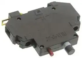
Illustrative purposes only

201 5A
Thermal Magnetic Circuit Breaker, 201 Series, 5 A, 1 Pole, 65 V, 250 V, DIN Rail
⚠️ Reference pricing provided. In case of supply shortages, we will connect you with our trusted procurement partners to ensure your project's continuity.
- Manufacturer: ETA
- Product type: Thermal Magnetic Circuit Breakers
- Product Range:201 Series; Current Rating:5A; No. of Poles:1 Pole; Voltage Rating V DC:65VDC; Voltage Rating VAC:250VAC; Circuit Breaker Mounting:DIN Rail; SVHC:No SVHC (15-Jan-2018); Approval Bodies:
- SVHC: No SVHC (17-Jan-2022)
- No. of Poles: 1 Pole
- Product Range: 201 Series
- Current Rating: 5A
- Voltage Rating VAC: 250V
- Voltage Rating VDC: 65V
- Circuit Breaker Mounting: DIN Rail
| Delivery and price | |
|---|---|
| Units per pack | 20 |
| Price | 26.05 € |
| Current stock | 10+ |
| Lead time | 30 days |
Datasheet

**Thermal-Magnetic Circuit Breaker 201/-WA**

**2** -

## **Description**

Single pole thermal-magnetic circuit breaker with tease-free, trip-free, snap action mechanism and two button operation (M-type TM CBE to EN 60934). Featuring a narrow profile housing, recessed terminals, standard EN rail mounting, and precision CBE performance. Approved to CBE standard EN 60934 (IEC 60934).

## **Typical applications**

|**Ordering information**<br>Process control systems, instrumentation, rail vehicles.<br>**Type No.**<br>**201**<br>singlepole,rail mounted version<br>**201-WA**<br>low-resistance version<br>**Option**<br>**2705**<br>fitted with adapter X 200 409 01<br>~~7,~~|**Technical data**<br>**standard type          low-resistance type**<br>**For further details please see chapter: Technical Information**<br>Voltage rating<br>Current rating range<br> Oo|
|---|---|
|**Current ratings**||
|**0.05...16 A** (type 201)<br>**0.05...10 A** (type 201-WA)|Typical life|
|**201 - .. - ....   -**<br>**10 A**<br>ordering example|Ambient temperature        -30...+60 °C|


**==> picture [153 x 20] intentionally omitted <==**

**----- Start of picture text -----**<br>
201-...                201-WA-...<br>standard type          low-resistance type<br>**----- End of picture text -----**<br>


## **Technical data**

## **For further details please see chapter: Technical Information**

|Voltage rating<br>AC 240 V (50/60 Hz); DC 65 V<br>(UL: AC 250 V,DC 80 V)<br>Oo|
|---|
|Current rating range<br>201: 0.05...16 A<br>201-WA: 0.05...10 A|
|Typical life<br>5,000 operations at 1 x IN, inductive<br>5,000 operations at 2 x IN,resistive|
|Ambient temperature        -30...+60 °C(-22...+140 °F)|
|Insulation co-ordination<br>rated impulse<br>pollution<br>(IEC 60664 and 60664 A)<br>withstand voltage<br>degree<br>2.5 kV<br>2<br>reinforced insulation  in operatingarea|
|Dielectric strength<br>(IEC 60664 and 60664A)<br>test voltage<br>operatingarea<br>AC 3,000 V|
|Insulation resistance<br>> 100 MΩ(DC 500 V)<br>Interrupting capacity Icn<br>201                   201-WA<br>0.05...0.8 A<br>0.05...0.2 A<br>self-limiting<br>1...2 A<br>0.3...2 A<br>200 A<br>2.5...16 A      2.5...10 A<br>400 A|
|Interrupting capacity<br>(UL 1077)<br>IN<br>UN<br>0.05...16 A    AC 250 V      1,000 A<br>0.05...16 A     DC 80 V<br>1,000 A|
|Degree of protection<br>operating area IP40<br>(IEC 60529/DIN 40050)terminal area  IP20|
|Vibration<br>5 g (57-500 Hz), ±0.38 mm (10-57 Hz)<br>to IEC 60068-2-6, test Fc<br>10 frequencycycles/axis|
|Shock<br>25 g (11 ms)<br>to IEC 60068-2-27,test Ea|
|Corrosion<br>96 hours at 5 % salt mist,|
|to IEC 60068-2-11,test Ka|
|Humidity<br>240 hours at 95 % RH<br>to IEC 60068-2-3,test Ca<br>Mass<br>approx. 60g|


The exact part number required can be built up from the table of choices shown above. Ordering references for optional features should be omitted if not required.

## **Standard current ratings and typical internal resistance values** EE

|**Current**<br>**Internal resistance (**Ω**)**<br>**rating (A)**<br>**201**<br>**201-WA**|**Current**<br>**Internal resistance (**Ω**)**<br>**rating (A)**<br>**201**<br>**201-WA**|
|---|---|
|0.05<br>447<br>211|3<br>0.19<br>0.054|
|0.1<br>131<br>48|4<br>0.090<br>0.035|
|0.2<br>40<br>12.4|5<br>0.061<br>0.025|
|0.3<br>19.3<br>5.7|6<br>0.041<br>< 0.02|
|0.4<br>10.4<br>3.1|7<br>0.034<br>< 0.02|
|0.5<br>7.1<br>2.0|8<br>< 0.02<br>< 0.02|
|0.6<br>4.3<br>1.32|10<br>< 0.02<br>< 0.02|
|0.8<br>2.5<br>0.76|12<br>< 0.02|
|1.67<br>0.49|14<br>< 0.02|
|1.5<br>0.61<br>0.21|15<br>< 0.02|
|0.38<br>0.101|16<br>< 0.02|
|2.5<br>0.24<br>0.078||


**Approvals** ~~re~~

|**Approvals**<br>~~re~~|~~re~~|~~re~~|
|---|---|---|
|**Authority**|**Voltage ratings**|**Current ratings**|
|VDE(EN 60 934)|AC 240 V,DC 65 V|0.05...16 A|
|CSA,UL|AC 250 V,DC 80 V|0.05...16 A|


05/06(020505) **www.e-t-a.com** ~~LT~~

## **Thermal-Magnetic Circuit Breaker 201/-WA**

**2**

## **Dimensions**

## **Installation drawing**

**==> picture [512 x 239] intentionally omitted <==**

**----- Start of picture text -----**<br>
45<br>1.77<br>ø8.5 11.5<br>.335 .453 conductor cross operating area<br>black section max. (reinforced insulation)<br>white 0.5 - 10 mm [2]<br>(AWG 20-AWG 8)<br>rigid conductor<br>0.5 - 6 mm [2]<br>(AWG 20-AWG 10)<br>flexible conductor<br>tightening torque<br>max. 0.8 Nm cable entry cable entry<br>12-14<br>.472-.551<br>mounting area<br>80 12.5<br>3.15 .492<br>symmetrical rail EN 50022-35x7.5<br>current rating in A slot for fitting labels from<br>Weidmüller<br>type dekafix<br>Phoenix<br>Phillips screw, size 2 to EN ISO 4757 type ZBFM5 or ZB8<br>11 .433 5<br>.197<br>OFF ON<br>53 2.09<br>43 1.69<br>7.5 .295 4.8 .189 6.5 .256<br>2<br>**----- End of picture text -----**<br>


## **Internal connection diagram**

**==> picture [249 x 123] intentionally omitted <==**

**----- Start of picture text -----**<br>
line  1<br>I ><br>2<br>**----- End of picture text -----**<br>


This is a metric design and millimeter dimensions take precedence ~~(~~[mm ] inch ~~)~~

The time/current characteristic curve depends on the ambient temperature prevailing. In order to eliminate nuisance tripping, please multiply the circuit breaker current ratings by the derating factor shown below. See also section 9 – Technical information. Ambient temperature °F       -22 -4 +14 +32   +73.4 +104 +122 +140 °C -30 -20 -10 0 +23 +40 +50 +60 Derating factor 0.76 0.79 0.83 0.88 1 1.08 1.16  1.24

## **Typical time/current characteristics**

**==> picture [512 x 265] intentionally omitted <==**

**----- Start of picture text -----**<br>
Type 201 0.05...7 A AC/DC  [1)] Type 201 8...16 A AC/DC  [1)] Type 201-WA 0.05...10 A DC/AC  [2)]<br>10000 10000 10000<br>1000 1000 1000<br>100 100 100<br>10 10 10<br>1 1 1<br>0.1 0.1 0.1<br>0.01 0.01 0.01<br>0.001 0.001 0.001<br>1 2 4 6 8 10 20 40 60 80100 1 2 4 6 8 10 20 40 60 80100 1 2 4 6 8 10 20 40 60 80100<br>… times rated current … times rated current … times rated current<br>+140 +60 °°CF +73.4 +23 °°CF -30 -22 °°CF<br>1) Magnetic tripping currents are increased by 20% on DC supplies.<br>2) Magnetic tripping currents are decreased by 20% on AC supplies.<br>Trip time in seconds Trip time in seconds Trip time in seconds<br>**----- End of picture text -----**<br>


05/06(020505)

120

**www.e-t-a.com**

**Thermal-Magnetic Circuit Breaker 201/-WA**

**2**

## **Accessories**

**Adapter** for EN rail 50035-G32 specified as a separate item **X 200 409 01**

**==> picture [184 x 68] intentionally omitted <==**

**----- Start of picture text -----**<br>
Adapter X 200 409 01 G profile<br>EN 50035-G32<br>20 .787<br>**----- End of picture text -----**<br>


## **Connector bus links -K10**

**X 210 589 01/** 2.5 mm[2] , (AWG 14) (black) up to 20 A max. load **X 210 589 02/** 1.5 mm[2] , (AWG 16) (brown) up to 13 A max. load

**==> picture [119 x 76] intentionally omitted <==**

**----- Start of picture text -----**<br>
ø2.5<br>50 pin lugs to DIN 46230 .099<br>tinned copper<br>~70 ~2.76<br>**----- End of picture text -----**<br>


**Bus bar X 221 498 01** (17-way) up to 70 A max. load

**==> picture [230 x 273] intentionally omitted <==**

**----- Start of picture text -----**<br>
16 x 12.5 = 200<br>16 x .492 = 7.87<br>12.5<br>.492<br>2.5 1.3<br>.099 .051<br>IEC 664 500 V/70 A (40 °C) CE<br>E-T-A [®]  GERMANY<br>207 3.5<br>8.15 .138<br>Supply terminal for bus bar<br>X 221 496 01<br>up to 70 A max. load<br>4.6<br>M5<br>.181<br>conductor size max. 10 mm [2]  (AWG 8)<br>rigid, solid or stranded<br>13 14.5<br>.512 .571<br>17<br>.669<br>29 1.14<br>14 .551<br>22 .866<br>1.3 .051<br>11.3 .445 5.2 .205<br>2.5 .098<br>9.7 .382<br>**----- End of picture text -----**<br>


This is a metric design and millimeter dimensions take precedence ~~(~~[mm ] inch ~~)~~

All dimensions without tolerances are for reference only. In the interest of improved design, performance and cost effectiveness the right to make changes in these specifications without notice is reserved.Product markings may not be exactly as the ordering codes. Errors and omissions excepted.

05/06(020505)

**www.e-t-a.com**
Updated at June 9, 2026
About Novapart
Novapart is a B2B electronic component broker specialising in stock shortages and cost reduction. We source hard-to-find parts and identify compliant alternatives across a catalogue of 410,000+ components from 500+ manufacturers.
Learn more →Stock Shortage Specialist
When a component is unavailable, discontinued or has an unacceptable lead time, we tap into our network of vetted European and Asian distributors to source what you need — without compromising on quality or traceability.
Request a quote →Compliant Alternatives
We identify pin-to-pin, electrically equivalent substitutes that meet the same certifications (RoHS, AEC-Q100, REACH) as your original specification — validated against datasheets, not just part numbers. Often at a lower cost.
BOM Analysis service →