
Image not available
Illustrative purposes only

09758
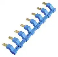
Relay Accessory, Jumper Link, 97 Series
⚠️ Reference pricing provided. In case of supply shortages, we will connect you with our trusted procurement partners to ensure your project's continuity.
- Manufacturer: FINDER
- Product type: Other Relay Accessories
- Accessory Type:Jumper Link; For Use With:-; Product Range:97 Series; SVHC:No SVHC (15-Jan-2019)
- SVHC: No SVHC (04-Feb-2026)
- For Use With: -
- Product Range: 97 Series
- Accessory Type: Jumper Link
| Delivery and price | |
|---|---|
| Units per pack | 50 |
| Price | 3.58 € |
| Current stock | 10+ |
| Lead time | 30 days |
Datasheet

**58 SERIES**

**B**

## **3 & 4 CO relay interface modules, 31 mm wide with Push-in terminals**

## **Ideal interface for PLC and electronic systems**

## **Type 58.P3**

- 3 CO 10 A

- Push-in terminals

## **Type 58.P4**

- 4 CO 7 A

- Push-in terminals

- AC coils or DC coils

- Supply status indication and EMC coil suppression module as standard

**==> picture [180 x 144] intentionally omitted <==**

**----- Start of picture text -----**<br>
S 58.P3 S 58.P4<br>ew ‘es><br>Meng<br>• 3 CO 10 A • 4 CO 7 A<br>• Push-in terminals • Push-in terminals<br>**----- End of picture text -----**<br>


- Identification label

- Cadmium Free contacts

- UL Listing (certain relay/socket combinations)

- 35 mm rail (EN 60715) mounting

## 58.P3 / 58.P4

Push-in terminals

|For outline drawing see page 7||Example: AC||||Example: DC|
|---|---|---|---|---|---|---|
|**Contact specification**<br>Contact configuration||3 CO (3PDT)||||4 CO (4PDT)|
|Rated current/Maximum peak current<br>A||10/20||||7/15|
|Rated voltage/<br>Maximum switchingvoltage|V AC|250/400||||250/250|
|Rated load AC1|VA|2500||||1750|
|Rated load AC15 (230 V AC)|VA|500||||350|
|Single phase motor rating (230 V AC)<br>kW||0.37||||0.125|
|Breaking capacity DC1: 30/110/220 V<br>A||10/0.25/0.12||||7/0.25/0.12|
|Minimum switching load|mW (V/mA)|300 (5/5)||||300 (5/5)|
|Standard contact material<br>**Coil specification**<br>Nominal voltage (UN)|V AC (50/60 Hz)|AgNi<br>12 - 24 - 48 - 110 - 120 - 230||||AgNi<br>12 - 24 - 48 - 110 - 120 - 230|
||V DC|12 - 24 - 48 - 125||||12 - 24 - 48 - 125|
|Rated power AC/DC|VA (50 Hz)/W|1.5/1||||1.5/1|
|Operating range|AC|(0.8…1.1)UN||||(0.8…1.1)UN|
||DC|(0.8…1.1)UN||||(0.8…1.1)UN|
|Holding voltage|AC/DC|0.8 UN/ 0.5 UN||||0.8 UN/ 0.5 UN|
|Must drop-out voltage<br>**Technical data**|AC/DC|0.2 UN/ 0.1 UN||||0.2 UN/ 0.1 UN|
|Mechanical life AC/DC|cycles|20 · 106/ 50 · 106||||20 · 106/ 50 · 106|
|Electrical life at rated load AC1|cycles|200 · 103||||150 · 103|
|Operate/release time|ms|10/5 (AC) - 10/15 (DC)|10/5 (AC) - 10/15 (DC)|||11/3 (AC) - 11/15 (DC)|
|Insulation between coil|||||||
|and contacts(1.2/50μs)<br>Dielectric strength<br>between open contacts<br>Ambient temperature range<br>Protection category|kV<br>V AC<br>°C|3.6<br>1000<br>–40…+70<br>IP 20<br>Ce~~GHL~~|~~@@~~|~~@B~~|~~B~~|3.6<br>1000<br>–40…+70<br>IP 20<br>®<br>~~RINAWis~~|
|**Approvals relay**(according to type)||Ce~~GHL~~|~~@@~~|~~@B~~|~~B~~|®<br>~~RINAWis~~|


**1**

**58 SERIES**

## **2, 3 & 4 CO relay interface modules,**

## **58.32**

**==> picture [25 x 7] intentionally omitted <==**

**----- Start of picture text -----**<br>
58.33<br>**----- End of picture text -----**<br>


**==> picture [26 x 7] intentionally omitted <==**

**----- Start of picture text -----**<br>
58.34<br>**----- End of picture text -----**<br>


## **27 mm wide with Screw terminals**

## **Ideal interface for PLC and electronic systems**

## **Type 58.32**

- 2 CO 10 A

- Screw terminals

## **Type 58.33**

**B**

- 3 CO 10 A

- Screw terminals

## **Type 58.34**

- 4 CO 7 A

- Screw terminals

- 2 CO 10 A

- Screw terminals

- 3 CO 10 A

- Screw terminals

   - 4 CO 7 A

   - Screw terminals

- AC coils or DC coils

- Supply status indication and EMC coil suppression module as standard

- Identification label

- Cadmium Free contacts

- UL Listing (certain relay/socket combinations)

- 35 mm rail (EN 60715) mounting

58.32 / 58.33 / 58.34 Screw terminals

|For outline drawing see page 7||Example: AC||Example: DC|Example: DC|Example: DC|Example: DC|Example: DC|||Example: AC|
|---|---|---|---|---|---|---|---|---|---|---|---|
|**Contact specification**<br>Contact configuration||2 CO (DPDT)||3 CO (3PDT)|||||||4 CO (4PDT)|
|Rated current/Maximum peak current<br>A||10/20|||10/20||||||7/15|
|Rated voltage/<br>Maximum switchingvoltage|V AC|250/400||250/400|||||||250/250|
|Rated load AC1|VA|2500|||2500||||||1750|
|Rated load AC15 (230 V AC)|VA|500|||500||||||350|
|Single phase motor rating (230 V AC)<br>kW||0.37|||0.37||||||0.125|
|Breaking capacity DC1: 30/110/220 V<br>A||10/0.25/0.12||10/0.25/0.12|||||||7/0.25/0.12|
|Minimum switching load|mW (V/mA)|300 (5/5)||300 (5/5)||300 (5/5)|||||300 (5/5)|
|Standard contact material<br>**Coil specification**<br>Nominal voltage (UN)|V AC (50/60 Hz)|AgNi<br>12 - 24 - 48 - 110 - 120 - 230||AgNi<br>12 - 24 - 48 - 110 - 120 - 230||||||12 - 24 - 48 - 110 - 120 - 230|AgNi<br>12 - 24 - 48 - 110 - 120 - 230|
||V DC|12 - 24 - 48 - 125||12 - 24 - 48 - 125|12 - 24 - 48 - 125||||||12 - 24 - 48 - 125|
|Rated power AC/DC|VA (50 Hz)/W|1.5/1|||1.5/1||||||1.5/1|
|Operating range|AC|(0.8…1.1)UN||(0.8…1.1)UN|||||||(0.8…1.1)UN|
||DC|(0.8…1.1)UN||(0.8…1.1)UN|||||||(0.8…1.1)UN|
|Holding voltage|AC/DC|0.8 UN/ 0.5 UN||0.8 U|0.8 UN/ 0.5 U||/ 0.5 UN||||0.8 UN/ 0.5 UN|
|Must drop-out voltage<br>**Technical data**|AC/DC|0.2 UN/ 0.1 UN||0.2 U|0.2 UN/ 0.1 U||/ 0.1 UN||||0.2 UN/ 0.1 UN|
|Mechanical life AC/DC|cycles|20 · 106/ 50 · 106||20 · 106/ 50 · 10|||/ 50 · 106||||20 · 106/ 50 · 106|
|Electrical life at rated load AC1|cycles|200 · 103||200 · 10||200 · 10|200 · 103||||150 · 103|
|Operate/release time|ms|10/5 (AC) - 10/15 (DC)||10/5 (AC) - 10/15 (DC)||||||11/3 (AC) - 11/15 (DC)||
|Insulation between coil||||||||||||
|and contacts(1.2/50μs)<br>Dielectric strength<br>between open contacts<br>Ambient temperature range<br>Protection category|kV<br>V AC<br>°C|3.6<br>1000<br>–40…+70<br>IP 20<br>C€~~GEL~~|~~GEL~~|3.6<br>1000<br>–40…+70<br>IP 20<br>~~@@BRINA~~|||||~~Wis~~|®<br>~~Wis~~|3.6<br>1000<br>–40…+70<br>IP 20|
|**Approvals relay**(according to type)||C€~~GEL~~|~~GEL~~|~~@@~~|~~@~~|~~B~~|~~B~~|~~RINA~~|~~Wis~~|®<br>~~Wis~~||


**2**

**58 SERIES**

**B**

**2, 3 & 4 CO relay interface modules, 27 mm wide with Screw terminals ATEX compliant (EX nA nC)**

**==> picture [55 x 7] intentionally omitted <==**

**----- Start of picture text -----**<br>
58.32 - x0xx<br>**----- End of picture text -----**<br>


**==> picture [54 x 7] intentionally omitted <==**

**----- Start of picture text -----**<br>
58.33 - x0xx<br>**----- End of picture text -----**<br>


## **58.34 - x0xx**

**Type 58.32 - x0xx**

- 2 CO 10 A

- Screw terminals

**Type 58.33 - x0xx**

- 3 CO 9 A

- Screw terminals

**Type 58.34 - x0xx**

- 4 CO 6 A

- Screw terminals

- AC coils or DC coils

- Supply status indication and EMC coil suppression module as standard

- 2 CO 10 A

- Screw terminals

- ATEX compliant

- 3 CO 9 A

- Screw terminals

- ATEX compliant

   - 4 CO 6 A

   - Screw terminals

   - ATEX compliant

- Mechanical indicator - optional on 2 & 4 CO types

- Identification label

- Cadmium Free contacts

- UL Listed

- Complies with:

- -EN 60079-0:2012 and EN 60079-15:2010

- -94/9/CE and 2014/34/UE

- 35 mm rail (EN 60715) mounting

58.32 / 58.33 / 58.34 - x0xx Screw terminals

**==> picture [497 x 415] intentionally omitted <==**

**----- Start of picture text -----**<br>
|||||||||||||||
|---|---|---|---|---|---|---|---|---|---|---|---|---|---|
|For outline drawing see page 7|Example: DC|Example: AC|Example: DC|
|Contact specification|
|Contact configuration|2 CO (DPDT)|3 CO (3PDT)|4 CO (4PDT)|
|Rated current/Maximum peak current|A|10/20|9/20|6/15|
|Rated voltage/|
|250/400|250/400|250/250|
|Maximum switching voltage|V AC|
|Rated load AC1|VA|2500|2250|1500|
|Rated load AC15 (230 V AC)|VA|500|500|350|
|Single phase motor rating (230 V AC)|kW|0.37|0.37|0.125|
|Breaking capacity DC1: 30/110/220 V|A|10/0.25/0.12|9/0.25/0.12|6/0.25/0.12|
|Minimum switching load|mW (V/mA)|300 (5/5)|300 (5/5)|300 (5/5)|
|Standard contact material|AgNi|AgNi|AgNi|
|Coil specification|
|Nominal voltage (UN)|V AC (50/60 Hz)|12 - 24 - 48 - 110 - 120 - 230|12 - 24 - 48 - 110 - 120 - 230|12 - 24 - 48 - 110 - 120 - 230|
|V DC|12 - 24 - 48 - 125|12 - 24 - 48 - 125|12 - 24 - 48 - 125|
|Rated power AC/DC|VA (50 Hz)/W|1.5/1|1.5/1|1.5/1|
|Operating range|AC|(0.8…1.1)UN|(0.8…1.1)UN|(0.8…1.1)UN|
|DC|(0.8…1.1)UN|(0.8…1.1)UN|(0.8…1.1)UN|
|Holding voltage|AC/DC|0.8 UN / 0.5 UN|0.8 UN / 0.5 UN|0.8 UN / 0.5 UN|
|Must drop-out voltage|AC/DC|0.2 UN / 0.1 UN|0.2 UN / 0.1 UN|0.2 UN / 0.1 UN|
|Technical data|
|Mechanical life AC/DC|cycles|20 · 10|[6]|/ 50 · 10|[6]|20 · 10|[6]|/ 50 · 10|[6]|20 · 10|[6]|/ 50 · 10|[6]|
|Electrical life at rated load AC1|cycles|150 · 10|[3]|150 · 10|[3]|150 · 10|[3]|
|Operate/release time|ms|11/3 (AC) - 11/15 (DC)|11/3 (AC) - 11/15 (DC)|11/3 (AC) - 11/15 (DC)|
|Insulation between coil|
|and contacts (1.2/50 μs)|kV|3.6|3.6|3.6|
|Dielectric strength|
|1000|1000|1000|
|between open contacts|V AC|
|Ambient temperature range|°C|–40…+70|–40…+70|–40…+70|
|Protection category|IP 20|IP 20|IP 20|
|Approvals relay|(according to type)|CE|&|€|®@|Mis|

**----- End of picture text -----**<br>


**3**

**58 SERIES**

## **Ordering information**

Example:  58 series, 35 mm rail (EN 60715) mounting, Push-in terminals interface module, 4 CO, 24 V DC coil, green LED + diode.

**==> picture [342 x 70] intentionally omitted <==**

**----- Start of picture text -----**<br>
A B C D<br>5 8 . P 4 . 9 . 0 2 4 . 0 0 5 0<br>A: Contact material D: Special versions<br>0 =  AgNi Standard<br>**----- End of picture text -----**<br>


## **D: Special versions**

**B Series Type**

0 =  Standard

5 =  AgNi + Au

3 =  Screw terminals

## **C: Options**

   - 5 =  Standard DC: green LED + diode (polarity +A1)

- 35 mm rail (EN 60715) mount

**B: Contact circuit**

- P =  Push-in terminals

**==> picture [48 x 7] intentionally omitted <==**

**----- Start of picture text -----**<br>
0 =  CO (nPDT)<br>**----- End of picture text -----**<br>


**==> picture [125 x 8] intentionally omitted <==**

**----- Start of picture text -----**<br>
6 =  Standard AC: green LED + Varistor<br>**----- End of picture text -----**<br>


35 mm rail (EN 60715) mount

## **No. of poles**

2 =  2 pole, 10 A

- 3 =  3 pole, 10 A 4 =  4 pole, 7 A

## **Coil version**

8 =  AC (50/60 Hz)

9 =  DC

**Coil voltage** See coil specifications

**Selecting features and options: only combinations in the same row are possible.** Preferred selections for best availability are shown in **bold** .

|**Type**|**Coil version **|**A**|||**B**|**C**|**D**|
|---|---|---|---|---|---|---|---|
|58.P3/P4/32/33/34|AC|**0**|-|5|0|**6**|0|
|58.P3/P4/32/33/34|DC|**0**|-|5|0|**5**|0|


## **Ordering information ATEX versions**

Example:  58 series, 35 mm rail (EN 60715), screw terminal interface module, 4 CO, 120 V AC, green LED, mechanical indicator, ATEX version

**A B C D 5 8 . 3 4 . 8 . 1 2 0 . 0 0 4 9**

**Series**

**Type**

3 =  Screw terminals

35 mm rail (EN 60715) mount

## **No. of poles**

- 2 =  2 pole, 10 A

- 3 =  3 pole, 9 A

- 4 =  4 pole, 6 A

## **A: Contact material**

0 =  AgNi Standard

- 2 = AgCdO

- 5 =  AgNi + Au

**B: Contact circuit**

0 =  CO (nPDT)

## **D: Special versions**

- 8 =  ATEX compliant (Ex nA nC) without mechanical indicator

- 9 =  ATEX compliant (Ex nA nC) with mechanical indicator (2 & 4 CO only)

## **C: Options**

- 4 = Module 99 LED (AC/DC)

- 5 =  Module 99

LED + Diode (DC)

## **Coil version**

8 =  AC (50/60 Hz)

9 =  DC

## **Coil voltage**

See coil specifications

**4**

**58 SERIES**

## **Technical data**

## **Insulation**

|Insulation according to EN 61810-1<br>insulation rated voltage<br>V <br>rated impulse withstand voltage  kV <br>pollution degree<br>overvoltage category|400 (2-3pole)|400 (2-3pole)|250 (4pole)|250 (4pole)|
|---|---|---|---|---|
||3.6 (2-3pole)<br>~~|~~||2.5 (4pole)||
||2<br>~~|~~<br>~~CT~~||2||
||III<br>~~CT~~<br>~~a~~||II||
|Insulation between coil and contacts (1.2/50μs)<br>kV <br>~~PC~~|3.6<br>~~a~~<br>~~PT~~<br>~~PC~~||||
|Dielectric strength between open contacts<br>V AC 1000<br>~~PC~~|V AC 1000<br>~~PC~~||||
|Dielectric strength between adjacent contacts<br>V AC <br>**Conducted disturbance immunity**<br>Burst (5…50)ns, 5 kHz, on A1 - A2<br>~~PC~~|2000 (58.32,58.33, 58.P3)<br>1550 (58.34, 58.P4)<br>EN 61000-4-4<br>level 4 (4 kV)<br>~~PC~~||||
|Surge (1.2/50 μs) on A1 - A2 (differential mode)<br>**Other data**<br>Bounce time: NO/NC<br>ms|EN 61000-4-5<br>level 4 (4 kV)<br> 1/3||||
|Vibration resistance (10…55)Hz: NO/NC<br>g|6/6||||
|Power lost to the environment<br>without contact current<br>W <br>with rated current<br>W|1||||
||3 (58.32, 58.34, 58.P4)<br>~~PT~~||4 (58.P3, 58.33)||
||**58.32/33/34 (screw terminals)**<br>~~PT~~<br>~~PT~~||**58.P3/P4 (Push-in terminals)**||
|Wire striplength<br>mm|8<br>~~PT~~<br>~~CT~~||8||
|Screw torque<br>Nm <br>;|0.5<br>~~Po~~<br>~~ee~~||—||
|Max. wire size<br>mm2 <br>AWG|solid cable<br>~~ee~~<br>~~ee~~|stranded cable<br>~~ee~~|solid cable<br>~~|~~|stranded cable|
||1 x 6 / 2 x 2.5<br>~~ee~~<br>~~ee~~|1 x 4 / 2 x 2.5<br>~~ee~~|2 x (0.5…1.5)<br>~~|~~|2 x (0.5…1.5)|
||1 x 10 / 2 x 14<br>~~ee~~<br>~~ee~~|1 x 12 / 2 x 14<br>~~ee~~|2 x (21…14)<br>~~|~~|2 x (21…14)|


**B**

## **Other data ATEX versions**

|**Other data ATEX versions**|||
|---|---|---|
|**Max current @ 70 °C**<br>Type 58.32<br>A|Single piece mount<br> 10|> 1 piece mount<br>7|
|Type 58.33<br>A 9|A 9<br>~~PT~~|6|
|Type 58.34<br>A <br>**Terminal**<br>Wire striplength<br>mm|6<br>5<br> 8<br>~~PT~~||
|Screw torque<br>Nm <br>@|0.5||
|Wire size<br>mm2 <br>AWG <br>~~PCPO~~|solid cable<br>~~PT~~<br>~~PC~~|stranded cable|
||1 x 2.5<br>~~PCPO~~|2 x 1.5|
||1 x 12<br>~~PCPO~~|2 x 16|


## **Markings - ATEX versions - ATEX, II 3G Ex nA nC IIC Gc**

|~~Re~~|~~Re~~|
|---|---|
|**MARKING**<br>~~Re~~||
|Specific markingof explosionprotection<br>~~Re~~||
|**II**<br>Component for surfaceplant(different from mines)||
|**3**<br>Category3: normal level ofprotection||
|**GAS**|**G**<br>Explosive atmosphere due topresence of combustiblegas vapour or mist|
||**Ex nA**<br>Non-sparkingequipment|
||**Ex nC**<br>Sealed device(type ofprotection for category3G)<br>~~$$~~|
||**IIC**<br>Gasgroup<br>~~$$~~|
||**Gc**<br>Equipment Protection Level<br>~~OS~~|
|**–40 °C ≤ Ta ≤ +70 °C**<br>Ambient temperature||
|**EPT 15 ATEX 0195 U**<br>EPT: laboratory which issues the CE type certificate<br>15: year of issue of certificate<br>0195: number of CE type certificate<br>U: ATEX component||


**5**

**58 SERIES**

## **Contact specification**

**==> picture [148 x 20] intentionally omitted <==**

**----- Start of picture text -----**<br>
F 58 - Electrical life (AC) v contact current<br>2 & 3 pole relays<br>**----- End of picture text -----**<br>


**==> picture [281 x 296] intentionally omitted <==**

**----- Start of picture text -----**<br>
B Resistive load - cosφ = 1<br>Inductive load - cosφ = 0.4<br>H 58 - Maximum DC1 breaking capacity<br>2 & 3 pole current limit<br>4 pole current limit<br>1 2 3 4 contacts in series<br>DC voltage (V)<br>Cycles<br>DC breaking current (A)<br>**----- End of picture text -----**<br>


## **F 58 - Electrical life (AC) v contact current**

4 pole relay

**==> picture [217 x 108] intentionally omitted <==**

**----- Start of picture text -----**<br>
Resistive load - cosφ = 1<br>Inductive load - cosφ = 0.4<br>Cycles<br>**----- End of picture text -----**<br>


- When switching a resistive load (DC1) having voltage and current values under the curve, an electrical life of ≥ 100 · 10[3] can be expected.

- In the case of DC13 loads, the connection of a diode in parallel with the load will permit a similar electrical life as for a DC1 load. Note: the release time for the load will be increased.

## **Coil specifications**

## **DC coil data**

|Nominal<br>voltage<br>UN|Coil code|Operating range<br>Umin<br>Umax|Operating range<br>Umin<br>Umax|Resistance<br>R|Rated coil<br>absorption<br>Iat UN|
|---|---|---|---|---|---|
|V||V|V|Ω|mA|
|12|**9**.012|9.6|13.2|140|86|
|24|**9**.024|19.2|26.4|600|40|
|48|**9**.048|38.4|52.8|2400|20|
|125|**9**.125|100|138|17300|7.2|


## **R 58 - DC coil operating range v ambient temperature**

**==> picture [254 x 158] intentionally omitted <==**

**----- Start of picture text -----**<br>
1<br>2<br>1 -   Max. permitted coil voltage.<br>2 -   Min. pick-up voltage with coil at ambient temperature.<br>**----- End of picture text -----**<br>


## **AC coil data**

|Nominal<br>voltage<br>UN|Coil code|Operating range<br>Umin<br>Umax|Operating range<br>Umin<br>Umax|Resistance<br>R|Rated coil<br>absorption<br>Iat UN(50 Hz)|
|---|---|---|---|---|---|
|V||V|V|Ω|mA|
|12|**8**.012|9.6|13.2|50|97|
|24|**8**.024|19.2|26.4|190|53|
|48|**8**.048|38.4|52.8|770|25|
|110|**8**.110|88|121|4000|12.5|
|120|**8**.120|96|132|4700|12|
|230|**8**.230|184|253|17000|6|


## **R 58 - AC coil operating range v ambient temperature**

**==> picture [254 x 147] intentionally omitted <==**

**----- Start of picture text -----**<br>
1<br>2<br>1 -   Max. permitted coil voltage.<br>**----- End of picture text -----**<br>


**==> picture [192 x 8] intentionally omitted <==**

**----- Start of picture text -----**<br>
2 -   Min. pick-up voltage with coil at ambient temperature.<br>**----- End of picture text -----**<br>


**6**

**58 SERIES**

**B**

|**Combinations**<br>**Code**<br>58.P3<br>58.P4<br>58.32<br>58.33<br>58.34<br>Certain relay/socket<br>combinations<br>**Outline drawing**|**Type**|**of socket**|**Type of relay**|**Module**|**Retaining clip**|
|---|---|---|---|---|---|
||94.P3||55.33|99.02|094.91.3|
||94.P4||55.34|99.02|094.91.3|
||94.02||55.32|99.02|094.91.3|
||94.03||55.33|99.02|094.91.3|
||94.04||55.34|99.02|094.91.3|
|||||||


**==> picture [55 x 121] intentionally omitted <==**

**==> picture [56 x 122] intentionally omitted <==**

**==> picture [96 x 126] intentionally omitted <==**

**==> picture [90 x 131] intentionally omitted <==**

58.32 58.33 58.34 Screw terminals Screw terminals Screw terminals

**==> picture [39 x 39] intentionally omitted <==**

**==> picture [39 x 39] intentionally omitted <==**

**==> picture [148 x 143] intentionally omitted <==**

**==> picture [146 x 229] intentionally omitted <==**

58.P3 58.P4 Push-in terminal Push-in terminal

**==> picture [39 x 40] intentionally omitted <==**

**==> picture [40 x 40] intentionally omitted <==**

**7**

**58 SERIES**

**==> picture [522 x 445] intentionally omitted <==**

**----- Start of picture text -----**<br>
Accessories<br>2-way jumper link  for type 58.P3 and 58.P4 094.52.1<br>Rated values 10 A - 250 V<br>———<br>Gf yy<br>( AY<br>094.52.1<br>B<br>2-way jumper link  for type 58.P3 and 58.P4 097.52<br>Rated values 10 A - 250 V<br>fl<br>097.52<br>eS Marker tag holder  for type 58.P3, 58.P4, 58.32, 58.33 and 58.34 | 097.00<br>097.00<br>sy<br>6-way jumper link  for type 58.32, 58.33, 58.34 094.06 (blue) 094.06.0 (black)<br>Rated values 10 A - 250 V<br>A<br>094.06<br>6-way jumper link  for type 58.P3 and 58.P4 094.56 (blue)<br>Rated values 10 A - 250 V<br>ZB a a<br>094.56<br>Sheet of marker tags , plastic, 48 tags, 6 x 12 mm 060.48<br>E<br>E<br>A<br>A<br>P<br>P<br>P A T E N T<br>P A T E N T<br>N<br>N<br>O<br>O<br>R<br>R<br>U<br>U<br>E<br>E<br>E<br>E<br>U<br>U<br>R<br>R<br>N<br>N<br>O<br>O<br>P<br>P<br>A<br>A<br>E<br>E<br>**----- End of picture text -----**<br>


**060.48**

## **Packaging codes**

**How to code and identify retaining clip and packaging options for sockets.** Example: **5 8 . P 4 . 9 . 0 2 4 . 0 0 5 0 S P A** ~~PoE~~ **A** Standard packaging **B** Blister packaging **SP** Plastic retaining clip **SM** Metallic retaining clip (58.32/33/34 - x0xx only)

**8**
Updated at June 7, 2026
About Novapart
Novapart is a B2B electronic component broker specialising in stock shortages and cost reduction. We source hard-to-find parts and identify compliant alternatives across a catalogue of 410,000+ components from 500+ manufacturers.
Learn more →Stock Shortage Specialist
When a component is unavailable, discontinued or has an unacceptable lead time, we tap into our network of vetted European and Asian distributors to source what you need — without compromising on quality or traceability.
Request a quote →Compliant Alternatives
We identify pin-to-pin, electrically equivalent substitutes that meet the same certifications (RoHS, AEC-Q100, REACH) as your original specification — validated against datasheets, not just part numbers. Often at a lower cost.
BOM Analysis service →