
Image not available
Illustrative purposes only

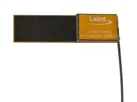
001-0014
RF Antenna, 2.4 to 2.48GHz, WiFi / Bluetooth, 2dBi, Linear, Adhesive / MHF1 Connector
⚠️ Reference pricing provided. In case of supply shortages, we will connect you with our trusted procurement partners to ensure your project's continuity.
- Manufacturer: EZURIO
- Product type:
- Gain: 2dBi
- SVHC: To Be Advised
- VSWR: 2
- Input Power: -
- Antenna Type: WiFi / Bluetooth
- Frequency Max: 2.48GHz
- Frequency Min: 2.4GHz
- Product Range: FlexPIFA Series
- Input Impedance: 50ohm
- Antenna Mounting: Adhesive / MHF1 Connector
- Antenna Polarisation: Linear
| Delivery and price | |
|---|---|
| Units per pack | 250 |
| Price | 2.64 € |
| Current stock | 10+ |
| Lead time | 30 days |
Datasheet

|™||▪Quick and easy installation<br>▪Adhesive holds to surface during humidity<br>exposure and hot/cold cycles<br>▪RoHS-compliant<br> FEATURESANDBENEFITS|▪Quick and easy installation<br>▪Adhesive holds to surface during humidity<br>exposure and hot/cold cycles<br>▪RoHS-compliant<br> FEATURESANDBENEFITS|▪Can be installed in the following ways:<br>–On different non-conductive surfaces<br>and thicknesses<br>–Near metals or the human body<br>–On flat or curved surfaces|
|---|---|---|---|
|||||
|Frequency (MHz)||2400 - 2480||
|Peak Gain(dBi)|||+2.0|
|Average Gain(dBi)|||> -1.5|
|VSWR(MHz)|||< 2.0:1|
|Impedance(Ω)|||50|
|Polarization|||Linear|
|||||
|MECHANICAL SPECIFICATIONS||||
|Antenna Type||Flexible Planar Inverted F Antenna(FlexPIFA)||
|Dimensions – mm(inches)||40.1 x 11.0 x 2.5|40.1 x 11.0 x 2.5(1.58 x 0.43 x 0.098)|
|Weight –g (oz.)||1.13(0.040)||
|Color||Clearyellow||
|Adhesive|||3M 100MP|
|Connector Mating Height (max) – mm||MHF1 (U.FL)<br>2.5<br>MHF4L<br>1.4||
|||||
|||||
|OperatingTemperature – °C(°F)||-40 to +85°C(-40 to +185°F)||
|Material Substance Compliance|||RoHS|


- Can be installed in the following ways: – On different non-conductive surfaces and thicknesses

- – Near metals or the human body

- – On flat or curved surfaces

|~~PARTNUMBER~~<br>~~|~~|~~|~~<br>~~CABLELENGTH~~<br>~~|~~|~~CONNECTOR~~|
|---|---|---|
|001-0014<br>~~PART NUMBER~~<br>~~|~~|100 mm<br>~~|~~<br>~~CABLE LENGTH~~<br>~~|~~<br>~~Pe~~|MHF1<br>~~CONNECTOR~~|
|001-0022|100 mm<br>~~Pe~~<br>~~Pe~~|MHF4L|
|001-0025|100 mm<br>~~Pe~~<br>~~Pe~~|MHF1|
|EFB2400A3S-13MHF1|130 mm<br>~~Pe~~<br>~~Pe~~|MHF1|
|EFB2400A3S-22MHF1|220 mm<br>~~Pe~~<br>~~Pt~~|MHF1|


**Note** : Specifications are based on the 100mm cable length, standard antenna version with MHF1 / U.FL connector.  Varying the cable length or type or connector will cause variations in these antenna specifications.

1 © Copyright 2023 Laird Connectivity All Rights Reserved

https://www.lairdconnect.com/

**Americas** : +1-800-492-2320 **Europe** : +44-1628-858-940 **Hong Kong** : +852 2762 4823

**==> picture [59 x 7] intentionally omitted <==**

**----- Start of picture text -----**<br>
RF Connector<br>**----- End of picture text -----**<br>


_**Figure 1: FlexPIFA mechanical drawing of 001-0014, 001-0022, and EFB2400A3S-22MHF1**_

2 © Copyright 2023 Laird Connectivity All Rights Reserved

https://www.lairdconnect.com/

**Americas** : +1-800-492-2320 **Europe** : +44-1628-858-940 **Hong Kong** : +852 2762 4823

**==> picture [59 x 7] intentionally omitted <==**

**----- Start of picture text -----**<br>
RF Connector<br>**----- End of picture text -----**<br>


_**Figure 2: FlexPIFA mechanical drawing of 001-0025**_

3 © Copyright 2023 Laird Connectivity All Rights Reserved

https://www.lairdconnect.com/

**Americas** : +1-800-492-2320 **Europe** : +44-1628-858-940 **Hong Kong** : +852 2762 4823

_**Figure 3: FlexPIFA mechanical drawing of EFB2400A3S-13MHF1**_

https://www.lairdconnect.com/

4 © Copyright 2023 Laird Connectivity All Rights Reserved

**Americas** : +1-800-492-2320 **Europe** : +44-1628-858-940 **Hong Kong** : +852 2762 4823

Antenna measurements such as VSWR were measured with an Agilent E5071C vector network analyzer. Radiation patterns were measured with a CMT Planar 804/1 vector network analyzer in a Howland Company 3100 chamber equivalent. Phase center is nine inches above the Phi positioner.

Flat surface measurements were done with the antenna centered on a 1.5 mm-thick plate of polycarbonate. Curved surface measurements were taken by placing the antenna on the inside and outside of different diameter PVC tubing.

_**Figure 4: Antenna chamber**_

_**Figure 5: Antenna VSWR measured on a 1.5 mm-thick plate of polycarbonate**_

5 © Copyright 2023 Laird Connectivity All Rights Reserved

https://www.lairdconnect.com/

**Americas** : +1-800-492-2320 **Europe** : +44-1628-858-940 **Hong Kong** : +852 2762 4823

**==> picture [48 x 78] intentionally omitted <==**

**----- Start of picture text -----**<br>
Z<br>. ~ Y<br>X  ca<br>**----- End of picture text -----**<br>


_**Figure 6: Flat surface setup**_

6 © Copyright 2023 Laird Connectivity All Rights Reserved

https://www.lairdconnect.com/

**Americas** : +1-800-492-2320 **Europe** : +44-1628-858-940 **Hong Kong** : +852 2762 4823

**==> picture [545 x 172] intentionally omitted <==**

**----- Start of picture text -----**<br>
Gain  - Vertical Polarization at 2400.0 (MHz) Theta (deg) Gain  - Horizontal Polarization at 2400.0 (MHz) Theta (deg) Gain  - Total at 2400.0 (MHz) Theta (deg)<br>90   0 90   0 90   0<br>150 120 -20-10010 60 30  15 30 45 60 75 90105120135150165 150 120 -20-10010 60 30  15 30 45 60 75 90105120135150165 150 120 -20-10010 60 30  15 30 45 60 75 90105120135150165<br>-30 -30 -30<br>| \\\ | | ) \ | \ \<br>180 0 180 0 180 0<br>210 330<br>210 330 210 330<br>240 270 300 NL 240 a _ ey 300 240 NXa _ ~ 300<br>270 270<br>Gain Summary (dBi) at 2400.0 (MHz)       min: -28.3 (dBi)      max: +1.4 (dBi)     avg: -5.5 (dBi)<br>Gain Summary (dBi) at 2400.0 (MHz)       min: -25.9 (dBi)      max: -2.7 (dBi)     avg: -8.0 (dBi) Gain Summary (dBi) at 2400.0 (MHz)       min: -13.3 (dBi)      max: +1.9 (dBi)     avg: -1.6 (dBi)<br>**----- End of picture text -----**<br>


_**Figure 7: Vertical, horizontal, and total gain patterns – 2400 MHz**_

_**Figure 8: Vertical, horizontal, and total gain plots – 2400 MHz**_

7 © Copyright 2023 Laird Connectivity All Rights Reserved

https://www.lairdconnect.com/

**Americas** : +1-800-492-2320 **Europe** : +44-1628-858-940 **Hong Kong** : +852 2762 4823

**==> picture [551 x 174] intentionally omitted <==**

**----- Start of picture text -----**<br>
Gain  - Vertical Polarization at 2440.0 (MHz) Theta (deg) Gain  - Horizontal Polarization at 2440.0 (MHz) Theta (deg) Gain  - Total at 2440.0 (MHz) Theta (deg)<br>90   0 90   0 90   0<br>10  15 10  15 10  15<br>120 60  30 45 120 60  30 45 120 60  30 45<br>0  60 0  60 0  60<br>150 -20-10 30  75 90105120135150165 150 -20-10 30  75 90105120135150165 150 -20-10 30  75 90105120135150165<br>-30 -30 -30<br>180 0 180 0 180 0<br>210 330 210 330<br>210 330<br>NS : x VY/ NO 240  ; ; BA 300 NS 240 4 300<br>240 300<br>270 270<br>270<br>Gain Summary (dBi) at 2440.0 (MHz)       min: -29.9 (dBi)      max: -2.8 (dBi)     avg: -8.0 (dBi) Gain Summary (dBi) at 2440.0 (MHz)       min: -12.1 (dBi)      max: +1.9 (dBi)     avg: -1.5 (dBi)<br>Gain Summary (dBi) at 2440.0 (MHz)       min: -22.5 (dBi)      max: +1.3 (dBi)     avg: -5.1 (dBi)<br>**----- End of picture text -----**<br>


**Figure 9: Vertical, horizontal, and total gain patterns – 2440 MHz**

_**Figure 10: Vertical, horizontal, and total gain plots – 2440 MHz**_

8 © Copyright 2023 Laird Connectivity All Rights Reserved

https://www.lairdconnect.com/

**Americas** : +1-800-492-2320 **Europe** : +44-1628-858-940 **Hong Kong** : +852 2762 4823

**==> picture [549 x 171] intentionally omitted <==**

**----- Start of picture text -----**<br>
Gain  - Vertical Polarization at 2480.0 (MHz) Theta (deg) Gain  - Horizontal Polarization at 2480.0 (MHz) Theta (deg) Gain  - Total at 2480.0 (MHz) Theta (deg)<br>90   0 90   0 90   0<br>10  15 10  15 10  15<br>120 60  30 120 60  30 120 60  30<br> 45  45  45<br>0  60 0  60 0  60<br> 75  75  75<br> 90  90  90<br>-10 105 -10 105 -10 105<br>150 30 120 150 30 120 150 30 120<br>135 135 135<br>-20 150 -20 150 -20 150<br>165 165 165<br>|{ -30 -30 -30<br>180 0 180 0 180 0<br>\ | ) } \ ( ) J | \ ; |<br>210 330 210 330 210 330<br>\NY 240 x : a\ 300 4 NO 240 —— ;4 300 J wy, 240 . V4 300 /<br>270 270 270<br>Gain Summary (dBi) at 2480.0 (MHz)       min: -20.8 (dBi)      max: +1.8 (dBi)     avg: -4.8 (dBi) Gain Summary (dBi) at 2480.0 (MHz)       min: -28.5 (dBi)      max: -2.4 (dBi)     avg: -7.8 (dBi) Gain Summary (dBi) at 2480.0 (MHz)       min: -13.1 (dBi)      max: +2.5 (dBi)     avg: -1.1 (dBi)<br>**----- End of picture text -----**<br>


**Figure 11: Vertical, horizontal, and total gain patterns – 2480 MHz**

_**Figure 12: Vertical, horizontal, and total gain plots – 2480 MHz**_

9 © Copyright 2023 Laird Connectivity All Rights Reserved

https://www.lairdconnect.com/

**Americas** : +1-800-492-2320 **Europe** : +44-1628-858-940 **Hong Kong** : +852 2762 4823

**==> picture [101 x 69] intentionally omitted <==**

**----- Start of picture text -----**<br>
Z<br>Y<br>X<br>**----- End of picture text -----**<br>


**Figure 13: Outer diameter setup**

10 © Copyright 2023 Laird Connectivity All Rights Reserved

https://www.lairdconnect.com/

**Americas** : +1-800-492-2320 **Europe** : +44-1628-858-940 **Hong Kong** : +852 2762 4823

**==> picture [544 x 169] intentionally omitted <==**

**----- Start of picture text -----**<br>
Gain  - Vertical Polarization at 2440.0 (MHz) Theta (deg) Gain  - Horizontal Polarization at 2440.0 (MHz) Theta (deg) Gain  - Total at 2440.0 (MHz) Theta (deg)<br>90   0 90   0 90   0<br>10  15 10  15 10  15<br>120 60  30 45 120 60  30 45 120 60  30 45<br>0  60 0  60 0  60<br> 75  75  75<br> 90  90  90<br>-10 105 -10 105 -10 105<br>150 -20 30 120135150 150 -20 30 120135150 150 -20 30 120135150<br>165 165 165<br>| / -30 \ | -30 : \ [ | -30 \ \<br>180 0 180 0 180 0<br>210 330 210 330 210 330<br>NN<br>240  a — Ba 300 NN 240 - 7oA 300 ae 240 : _va 300<br>270 270 270<br>Gain Summary (dBi) at 2440.0 (MHz)       min: -36.9 (dBi)      max: +2.3 (dBi)     avg: -5.4 (dBi) Gain Summary (dBi) at 2440.0 (MHz)       min: -26.3 (dBi)      max: -2.5 (dBi)     avg: -7.7 (dBi) Gain Summary (dBi) at 2440.0 (MHz)       min: -11.9 (dBi)      max: +3.1 (dBi)     avg: -1.0 (dBi)<br>**----- End of picture text -----**<br>


_**Figure 14: Vertical, horizontal, and total gain patterns – 2440 MHz**_

_**Figure 15: Vertical, horizontal, and total gain plots – 2440 MHz**_

11 © Copyright 2023 Laird Connectivity All Rights Reserved

https://www.lairdconnect.com/

**Americas** : +1-800-492-2320 **Europe** : +44-1628-858-940 **Hong Kong** : +852 2762 4823

**==> picture [69 x 66] intentionally omitted <==**

**----- Start of picture text -----**<br>
Z<br>Y<br>X<br>**----- End of picture text -----**<br>


_**Figure 16: Inner diameter setup**_

12 © Copyright 2023 Laird Connectivity All Rights Reserved

https://www.lairdconnect.com/

**Americas** : +1-800-492-2320 **Europe** : +44-1628-858-940 **Hong Kong** : +852 2762 4823

**==> picture [549 x 170] intentionally omitted <==**

**----- Start of picture text -----**<br>
Gain  - Vertical Polarization at 2440.0 (MHz) Theta (deg) Gain  - Horizontal Polarization at 2440.0 (MHz) Theta (deg) Gain  - Total at 2440.0 (MHz) Theta (deg)<br>90   0 90   0 90   0<br>10  15 10  15 10  15<br>120 60  30 45 120 60  30 45 120 60  30 45<br>0  60 0  60 0  60<br> 75  75  75<br> 90  90  90<br>-10 105 -10 105 -10 105<br>150 -20 30 120135150 150 -20 30 120135150 150 -20 30 120135150<br>165 165 165<br>-30 -30 -30<br>180 0 180 0 180 0<br>\ ; : | / \ XK / \ - | |<br>210 330 210 330 210 330<br>240 300 240 300 240 300<br>270 270 270<br>Gain Summary (dBi) at 2440.0 (MHz)       min: -33.0 (dBi)      max: -3.0 (dBi)     avg: -8.3 (dBi)<br>Gain Summary (dBi) at 2440.0 (MHz)       min: -28.2 (dBi)      max: +2.9 (dBi)     avg: -4.0 (dBi) Gain Summary (dBi) at 2440.0 (MHz)       min: -19.0 (dBi)      max: +3.0 (dBi)     avg: -1.4 (dBi)<br>**----- End of picture text -----**<br>


_**Figure 17: Vertical, horizontal, and total gain patterns – 2440 MHz**_

_**Figure 18: Vertical, horizontal, and total gain plots – 2440 MHz**_

13 © Copyright 2023 Laird Connectivity All Rights Reserved

https://www.lairdconnect.com/

**Americas** : +1-800-492-2320 **Europe** : +44-1628-858-940 **Hong Kong** : +852 2762 4823

**==> picture [353 x 125] intentionally omitted <==**

**----- Start of picture text -----**<br>
Strong E-Field<br>Between Plates Fringing Fields<br>Main Element<br>cf ce owe oe FS ee le CF ER EtE fl PEP es we LS nels<br>tis STE a SR Ta ea NOS VY ay a be apne i accl Sarhs<br>—————— eS “‘~ ‘Ss . ‘ . .<br>erryEW WOP ede oo be Tt WONa  NNNaes a aceTe<br>Ground Plate<br>**----- End of picture text -----**<br>


_**Figure 19: E-field radiation from FlexPIFA – taken from CST simulation**_

The main element should be kept clear of any non-metal objects (such as plastics) on top of it by at least three millimeters (see Figure 20). Similarly, the two long sides of the FlexPIFA should be kept clear of any non-metal object by at least two millimeters (See Figure 21). A onemillimeter clearance should be observed from the ground wall to any non-metal object. Mounting the FlexPIFA in a situation that does not allow for these clearance recommendations may change the gain characteristics stated in the datasheet, which could impact overall range of the wireless system.

_**Figure 20: Top clearance**_

**==> picture [337 x 55] intentionally omitted <==**

**----- Start of picture text -----**<br>
Cable-Side<br>Cable-Side<br>2 mm 1 mm<br>**----- End of picture text -----**<br>


_**Side Clearance**_

_**Ground Wall Clearance**_

_**Figure 21: Side and ground wall clearance**_

14 © Copyright 2023 Laird Connectivity All Rights Reserved

https://www.lairdconnect.com/

**Americas** : +1-800-492-2320 **Europe** : +44-1628-858-940 **Hong Kong** : +852 2762 4823

The ideal material on which to mount the FlexPIFA is 1.5-millimeter thick polycarbonate for maximum performance. However, as previously mentioned, the FlexPIFA can tolerate other non-metallic surfaces and thicknesses and still radiate effectively. Depending on the type of material, the FlexPIFA may be detuned.

The coaxial cable feeding the FlexPIFA should be routed away from the antenna. Do not run the coaxial cable over the top of the FlexPIFA or near the tip of the main element. The cable should be routed perpendicular to the side of the FlexPIFA (this is the way the cable comes assembled) or away from the ground wall. These options are shown in Figure 22.

## **Perpendicular to the side**

**Away from the ground wall**

_**Figure 22: Recommended cable routing**_

As with any antenna, care should be taken not to place conductive materials or objects near the antenna (except as described in the next section). The radiated fields from the antenna induce currents on the surface of the metal; as a result, those currents then produce their own radiation. These re-radiating fields from the metal interfere with the fields radiating from the FlexPIFA (this is true for any antenna). Other objects, such as an LCD display, placed close to the antenna may not affect its tuning but it can distort the radiation pattern. Materials that absorb electromagnetic fields should be kept away from the antenna to maximize performance. Common things to keep in mind when placing the antenna:

- Wire routing

- Speakers – These generate magnetic fields

- Metal chassis and frames

- Battery location

- Proximity to human body

- Display screen – These absorb radiation

- Paint – Do not use metallic coating or flakes

15 © Copyright 2023 Laird Connectivity All Rights Reserved

https://www.lairdconnect.com/

**Americas** : +1-800-492-2320 **Europe** : +44-1628-858-940 **Hong Kong** : +852 2762 4823

One of the unique features of the FlexPIFA is its ability to flex. However, due to the adhesive, there are limits as to how much the antenna can be flexed and remain secured to the device. The FlexPIFA should not be flexed in a convex position with a radius less than 16 millimeters. Going smaller than this may result in the antenna peeling off the surface over time. Should a tighter radius of curvature be required, contact Laird Connectivity for assistance.

_**Figure 23: Convex-mounted**_

The FlexPIFA should not be flexed in a concave position with a radius less than 25 millimeters. In this scenario, the limiting factor is performance. The ground plate of the antenna is pressed closer to the main element. As previously discussed in the introduction of this datasheet, the fringing fields developing off the end of the element are responsible for most of the radiation. In a concave position with a radius of curvature less than 25 millimeters, the fringing fields are adversely affected, and gain suffers. If a tighter radius of curvature is required, contact Laird Connectivity for assistance.

_**Figure 24: Concave-mounted**_

The FlexPIFA is not designed to be twisted or crumpled. The adhesive back should lay flush with the surface on which it is mounted.

16 © Copyright 2023 Laird Connectivity All Rights Reserved

https://www.lairdconnect.com/

**Americas** : +1-800-492-2320 **Europe** : +44-1628-858-940 **Hong Kong** : +852 2762 4823

The FlexPIFA can tolerate being mounted on conductive surfaces. There will be some detuning of the antenna, which translates into some gain reduction. Even though the FlexPIFA is optimized to work on non-metallic surfaces, it still radiates efficiently due to the fringing fields (see Figure 19). The ground plate of the FlexPIFA carries the adhesive backing; placing the antenna onto a metal surface simply enlarges the size of the ground beneath the main element. Previously, the fringing fields only interacted with the small ground of the FlexPIFA, however they are now interacting with the much larger ground. The fringing fields still develop and radiate, but the antenna will no longer tune as well to the 2.4 GHz frequency band. Consequently, the VSWR increases and there is some loss in radiated power. If the FlexPIFA cannot meet your range requirements after being implemented on a metal surface, contact Laird Connectivity for a custom antenna build to help meet your application needs.

_**Figure 25: FlexPIFA mounted on metal**_

**Do not mount the FlexPIFA where metal is within ten millimeters above the main element** (see Figure 27). Not only does this severely limit the radiation pattern (mainly due to the re-radiation problem previously described) it detunes the antenna inside of this range.

Similarly, the two long sides of the FlexPIFA should be kept clear of any metal object by at least five millimeters. These keep out requirements pertaining to _**conductive**_ materials only and are different from those listed in the previous sections which apply to _**non-conductive**_ materials. In general, it is good practice to always keep metals as far away from the antenna as possible.

For the best performance, a spacer should be placed between the FlexPIFA and the conductive surface (see Figure 26). The spacer should be 1.5 millimeters thick polycarbonate. This will significantly improve performance and tuning of the FlexPIFA on a metal surface. Other nonconductive materials such as ABS plastic can be used; however, polycarbonate provides the best results.

_**Figure 26: FlexPIFA mounted on metal Surface with 1.5 mm thick polycarbonate spacer**_

17 © Copyright 2023 Laird Connectivity All Rights Reserved

https://www.lairdconnect.com/

**Americas** : +1-800-492-2320 **Europe** : +44-1628-858-940 **Hong Kong** : +852 2762 4823

**==> picture [46 x 11] intentionally omitted <==**

**----- Start of picture text -----**<br>
10 mm<br>**----- End of picture text -----**<br>


_**Figure 27: Metal near main element**_

For body-worn applications, the FlexPIFA can tolerate the presence of the human body. We do not recommend that you mount the antenna directly on body tissue to avoid detuning the FlexPIFA.

Additionally, the human body is an excellent absorber of 2.4 GHz RF signals. As a result, expect a reduction in range due to the presence of a body. In a body-worn application, the ground plate of the FlexPIFA should be closest to the body tissue. The main element should be pointed away from the body. Additionally, for handheld devices, the FlexPIFA should be mounted in a location where it is not covered by the hand. If the antenna is mounted in a location where the main element is covered or near a human body, ensure that there is at least a ten-millimeter separation distance between the main element and the body as shown in Figure 27.

Additionally, when the FlexPIFA is mounted very close to body tissue, use a spacer to create separation distance between the body tissue and ground plate. This ensures maximum performance and prevents the antenna from detuning. As previously mentioned, the ideal spacer material is 1.5 mm thick polycarbonate.

Quite often this separation distance between the body tissue and the FlexPIFA is already provided by the enclosure. Figure 28 is an example of a bracelet with the FlexPIFA integrated inside it. The enclosure provides enough spacing between the antenna and body tissue to prevent any major detuning. The enclosure is made of polycarbonate.

_**Figure 28: FlexPIFA integrated into bracelet**_

18 © Copyright 2023 Laird Connectivity All Rights Reserved

https://www.lairdconnect.com/

**Americas** : +1-800-492-2320 **Europe** : +44-1628-858-940 **Hong Kong** : +852 2762 4823

19 © Copyright 2023 Laird Connectivity All Rights Reserved

https://www.lairdconnect.com/

**Americas** : +1-800-492-2320 **Europe** : +44-1628-858-940 **Hong Kong** : +852 2762 4823

Please contact your local Laird Connectivity sales representative or our support team for further assistance:

**Support Center** https://www.lairdconnect.com/resources/support

**Phone** Americas: +1-800-492-2320 Europe: +44-1628-858-940 Hong Kong: +852 2762 4823 **Web** https://www.lairdconnect.com/internal-antennas

**Address** Laird Connectivity 50 S. Main Street, Suite 1100 Akron, OH 44308

© Copyright 2023 Laird Connectivity. All Rights Reserved. Patent pending. Any information furnished by Laird Connectivity and its agents is believed to be accurate and reliable. All sales@lairdconnect.com specifications are subject to change without notice. Responsibility for the use and application of Laird Connectivity materials or products rests with the end user since Laird Connectivity and its agents cannot be aware of all potential uses. Laird Connectivity makes no warranties as to non-infringement nor as to the fitness, merchantability, or sustainability of any Laird Connectivity support@lairdconnect.com materials or products for any specific or general uses. Laird Connectivity or any of its affiliates or agents shall not be liable for incidental or consequential damages of any kind. All Laird www.lairdconnect.com Connectivity products are sold pursuant to the Laird Connectivity Terms and Conditions of Sale in effect from time to time, a copy of which will be furnished upon request. Nothing herein provides a license under any Laird Connectivity or any third-party intellectual property right.

20 © Copyright 2023 Laird Connectivity All Rights Reserved

https://www.lairdconnect.com/

**Americas** : +1-800-492-2320 **Europe** : +44-1628-858-940 **Hong Kong** : +852 2762 4823
Updated at June 3, 2026
About Novapart
Novapart is a B2B electronic component broker specialising in stock shortages and cost reduction. We source hard-to-find parts and identify compliant alternatives across a catalogue of 410,000+ components from 500+ manufacturers.
Learn more →Stock Shortage Specialist
When a component is unavailable, discontinued or has an unacceptable lead time, we tap into our network of vetted European and Asian distributors to source what you need — without compromising on quality or traceability.
Request a quote →Compliant Alternatives
We identify pin-to-pin, electrically equivalent substitutes that meet the same certifications (RoHS, AEC-Q100, REACH) as your original specification — validated against datasheets, not just part numbers. Often at a lower cost.
BOM Analysis service →