


ZX-GT28S41
Sensor, Laser Photo, PNP, 500 mm, 21.6 VDC to 26.4 VDC
- Manufacturer: OMRON INDUSTRIAL AUTOMATION
- Product type:
- SVHC: To Be Advised
- Product Range: ZX Series
- Sensing Range Max: 500mm
- Sensor Output Type: PNP
- Supply Voltage DC Max: 26.4V
- Supply Voltage DC Min: 21.6V
| Delivery and price | |
|---|---|
| Units per pack | 1 |
| Price | 2916.24 € |
| Current stock | 10+ |
| Lead time | 30 days |
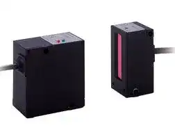
## Smart Laser Micrometer **ZX-GT**

- High accuracy: 5-10 µm

- All surfaces

- Long sensing distance: < 500 mm

- Line width up to 28 mm

- Calculation unit for multiple heads

- Fast sampling time: 0.5 ms

- PC software for setup

## Ordering Information

Sensors **Appearance Optical system Measuring Sensing Resolution Output type Model width distance** ~~eess~~ Separate type Through-beam 28 mm 0 to 500 mm 10 µm NPN ZX-GT28S11 PNP ZX-GT28S41 ~~gi YT i~~ Integrated type 40 mm NPN ZX-GT2840S11 PNP ZX-GT2840S41 || ~~Ee~~

Controller

|**Appearance**<br>~~ee~~|**Power supply**<br>~~ee~~<br>~~ee~~|**Output type**<br>~~ee~~<br>~~ee~~|**Model**<br>~~ee~~|
|---|---|---|---|
||DC<br>~~ee ~~|NPN<br> ~~ee~~|ZX-GTC11|
|||PNP|ZX-GTC41|


## Accessories (Order Separately)

Set of Interface Unit and Setup software PCs **Output type Model** NPN ZX-GIF11A PNP ZX-GIF41A ~~———~~ Interface Unit(RS-232C/Binary output) **Appearance Power supply Output type Model** DC NPN ZX-GIF11 PNP ZX-GIF41

**ZX-GT**

1

|Setup software PCs|Setup software PCs||Receiver-Controller Extension Cable|
|---|---|---|---|
|Calculating Units<br>**Name**<br>**Model**<br>Smart Monitor GT<br>ZX-GSW11<br>**Appearance**<br>**Model**<br>ZX-CAL2<br>~~ee ~~|||**Cable length**<br>**Model**<br>**Quantity**<br>**Standard cable**<br>**Flexible cable**<br>1 m<br>ZX-XGC1A<br>ZX-XGC1R<br>1 m<br>2 m<br>ZX-XGC2A<br>ZX-XGC2R<br>5 m<br>ZX-XGC5A<br>ZX-XGC5R<br>8 m<br>ZX-XGC8A<br>ZX-XGC8R<br>20 m<br>ZX-XGC20A<br>ZX-XGC20R<br>Up to two extension cables can be connected. However, be sure to limit the total extension<br> ~~===~~|
||||cable length between the receiver and the Controller to 30 meters (including the receiver|
||||cable).|


## Specifications

Sensor

|**Item**<br>~~GC~~|**ZX-GT28S11**<br>~~GC~~|**ZX-GT2840S11**<br>~~GC~~|**ZX-GT28S41**<br>~~GC~~|**ZX-GT2840S41**<br>~~GC~~|
|---|---|---|---|---|
|Output type<br>~~GG~~<br>~~eG~~|NPN<br>~~GG~~<br>~~eG~~<br>~~GF~~||PNP<br>~~GG~~<br>~~GF~~||
|Appearance<br>~~eG~~|Separate type<br>~~eG~~|Integrated type<br>~~GF~~|Separate type<br>~~GF~~|Integrated type|
|Light source<br>~~eG~~|Visible semiconductor laser diode (wavelength 650 nm, CLASS 1 of EN60825-1/IEC60825-1, CLASS of<br>FDA(21CFR 1040.10 and 1040.11)<br>~~eG~~<br>~~GF~~||||
|Measuring width<br>~~Ge~~<br>~~eG~~|28 mm<br>~~Ge~~<br>~~eG~~<br>~~GG~~||||
|Sensing distance<br>~~eG~~<br>~~ee~~|0 to 500 mm<br>~~eG~~<br>~~ee~~|40 mm<br>~~GG~~<br>~~GG~~|0 to 500 mm<br>~~GG~~<br>~~GG~~|40 mm|
|Minimum sensing object<br>~~eG~~<br>~~ee~~|0.5mm dia.(*1)<br>~~eG~~<br>~~ee~~|0.2 mm dia.<br>~~GG~~<br>~~GG~~|0.5 mm dia.(*1)<br>~~GG~~<br>~~GG~~|0.2 mm dia.|
|Linearity<br>~~ee~~<br>~~es~~|±0.1%F.S.(*2)<br>~~ee~~<br>~~GG~~<br>~~es~~||||
|Resolution<br>~~ee~~|10 µm (number of process values to average: 16)(*3)<br>~~ee~~||||
|Temperature characteristic<br>~~es~~|±0.01%F.S/C(*4)<br>~~es~~||||
|Indicators (emitter)<br>~~Gn~~|Laser ON indicator (green), laser alarm indicator (red)<br>~~Gn~~||||
|Indicator (receiver)<br>~~Gn~~<br>~~ee~~|Optical axis setting indicator (green)<br>~~Gn~~<br>~~ee~~||||
|Laser OFF input/sync input|ON: Short-circuited with 0 V or 1.5 V max.<br>OFF: Open (leakage current: 0.1 mA max.)||ON: Short-circuited with power supply voltage or<br>power supply voltage -1.5 V max.<br>OFF: Open (leakage current: 0.1 mA max.)||
|Laser deterioration alarm output|NPN open-collector output<br>30 VDC 20 mA max.<br>Residual voltage 1.2 V max.||PNP open-collector output<br>30 VDC 20 mA max.<br>Residual voltage 2 V max.||
|Power consumption (emitter)<br>~~Ge~~|30 mA max.<br>~~Ge~~||||
|Power supply voltage (emitter)<br>~~Gn~~|24 VDC +10%, -15% ripple (p-p) 10% max.<br>~~Gn~~||||
|Dielectric strength<br>~~eG~~|1,000 VAC, 50/60 Hz for 1 min<br>~~eG~~||||
|Insulation resistance<br>~~Gn~~|20 MΩ(at 500 VDC megger)<br>~~Gn~~||||
|Operating ambient illumination<br>(emitter)|3,000 lx (incandescent light)||||
|Operating ambient illumination<br>(receiver)|1,000 lx (incandescent light)(*5)<br>~~pT~~||||
|Ambient temperature|Operating: 0 to +40°C Storage: -15 to +50°C(with no icing or condensation)||||
|Ambient humidity<br>~~eG~~|Operating and storage: 35 to 85% (with no condensation)<br>~~eG~~||||
|Vibration resistance (durability)<br>~~Gn~~|10 to 150 Hz Single-amplitude: 0.75 mm for 80 min each in X, Y and Z directions<br>~~Gn~~||||
|Degree of protection<br>~~ee~~|IEC60529 IP40<br>~~ee~~||||
|Cable length<br>~~Gn~~|2 m<br>~~Gn~~||||
|Material<br>~~eS~~|Case: aluminum die-cast, Lens: glass<br>~~eS~~||||
|Weight (packed state)<br>~~pO~~|Approx. 550 g<br>~~pO~~|Approx. 570 g<br>~~pO~~|Approx. 550 g<br>~~pO~~|Approx. 570 g<br>~~pO~~|
|Accessories<br>~~A~~|Laser warning labels, Instruction Sheet<br>~~A~~||||


*2: Linearity is given to be a typical error with respect to an ideal straight line when the distance between the emitter and receiver is 100 mm and light is blocked at a distance of 50 mm from the receiver. (On the ZX-GT2840@@, the measurement object is measured at a distance of 20 mm from the receiver.)

*3: The amount of fluctuation (±3σ) in the analog output when the distance between the emitter and receiver is 100 mm and a ZX-GTC@@ is connected

*4: Change in the light cutoff value on one side when the distance between the emitter and receiver is 100 mm and the light is half-cutoff at a distance of 50 mm from the receiver (On the ZXGT2840@@, the measurement object is measured at a distance of 20 mm from the receiver.)

*5: Standard mode (NORM) used

Displacement sensors / Width-measuring Sensors

2

## Controller

|**Item**|**Item**|**ZX-GTC11**|**ZX-GTC41**|
|---|---|---|---|
|Output type||NPN|PNP|
|Measurement cycle(*1)||1.5 ms (standard mode (NORM))<br>0.5 ms (high-speed mode (FAST))(*2)||
|Samples to average||1/2/4/8/16/32/64/128/256/512/1024/2048/4096||
|Analog output(*3)||For current output: 4 to 20 mA/F.S., max. load resistance 300Ω<br>For voltage output: ±4 V, (±5 V, 1 to 5 V(*4)), output impedance 100Ω||
|Timing input, bank switching input,<br>zero reset input, reset input||ON: short-circuited with 0V or 1.5V max.<br>OFF: Open (leakage current: 0.1 mA max.)|ON: short-circuited with power supply voltage or<br>power supply voltage -1.5V max.<br>OFF: Open (leakage current: 0.1 mA max.)|
|HIGH/PASS/LOW<br>Judgment output(*5)<br>Sync output(*6)||NPN open-collector output<br>30 VDC 50 mA max.<br>Residual voltage 1.2 V max.|PNP open-collector output<br>30 VDC 50 mA max.<br>Residual voltage 2 V max.|
|Indicator||Judgment output indicator: HIGH (orange), PASS (green), LOW (orange)<br>Main display (red) Sub-display (yellow) Bank 1/2 (orange), zero reset (green)||
|Main<br>functions|Number of registered<br>setups|2 banks||
||Measurement Mode|Interrupted beam width measurement, incident beam width measurement, outer diameter measure-<br>ment, center position measurement, IC lead pitch, IC lead width judgment, specified edge measurement,<br>wire position measurement, glass edge position measurement||
||Display during<br>measurement|Measured value, resolution, threshold, voltage output value, current output value (number of display dig-<br>its can be changed)||
||Zero reset functions|Offset setting of zero reset value, zero reset value memory||
||Hold|Sample hold, peak hold, bottom hold, peak-to-peak hold, average hold, delay hold||
||Timer functions|ON delay, OFF delay, one-shot||
||Adjustment functions|Optical Axis adjust mode/light intensityt writing mode, variable binary level, variable edge filter, analog<br>output scaling||
||Calculation|2 Possible on up to two Controllers (Calculation Unit ZX-CAL2 is required for connecting Controllers to<br>each other.) A-B, A+B, width||
||Other|Measurement cycle setting, threshold setting, hysteresis setting, initialization, key lock||
|Temperature characteristic||±0.005%F.S./°C||
|Current consumption||150 mA max. (including receiver)||
|Power supply voltage||24 VDC +10%, -15% ripple (p-p) 10% max.||
|Dielectric strength||1,000 VAC, 50/60 Hz for min||
|Insulation resistance||20 MΩ(at 500 VDC megger)||
|Ambient temperature||Operating: 0 to +50°C Storage: -15 to +60°C (with no icing or condensation)||
|Ambient humidity||Operating and storage: 35 to 85% (with no condensation)||
|Vibration resistance(durability)||10 to 150 Hz Single-amplitude: 0.35 mm for 80 min each in X, Y and Z directions||
|Degree of protection||IEC60529 IP20||
|Cable length||2 m||
|Material||Case: PBT (polybutylene terephthalate), Cover: Polycarbonate||
|Weight (packed state)||Approx. 330 g||
|Accessories||Instruction Sheet||


*1: The first response time is "measurement cycle x (number of samples to average setting + 1) + 1 ms" max. For the second response time onwards, the specified measurement cycle time is output.

*2: The response time in the high-speed mode (FAST) for the IC lead pitch and IC lead width judgment modes is 1 ms.

*3: Current/voltage can be switched using the switch provided on the rear of the Controller.

*4: Can be set by the analog output scaling function.

*5: The error (ERR) state is displayed when all HIGH/PASS/LOW outputs turn OFF.

*6: Normally, wire the sync output wire directly to the emitter's sync input wire and run the Controller in the standard mode. On an NPN type Controller, use an NPN type emitter, and on a PNP type Controller, use a PNP type emitter. Wiring of the sync wires is not required when the Controller is run in the high-speed mode.

(Note, however, that the Controller becomes more susceptible to the influence of ambient light in this case.)

**ZX-GT**

3

## Interface Unit

|**Item**|**ZX-GIF11/-GIF11A**|**ZX-GIF41/-GIF41A**|
|---|---|---|
|Compatible Controller|ZX-GTC11|ZX-GTC41|
|Indicator|Power ON (green), Controller communications (orange), Controller communications error (red), RS-<br>232C communications (orange), RS-232C communications error (red), binary output (orange)||
|Communications port|RS-232C (9-pin D-sub connector)||
|12-bit binary output<br>(D11 toD0, GATE)|NPN open-collector output<br>30 VDC 20 mA max.<br>Residual voltage 1.2 V max.|PNP open-collector output<br>30 VDC 20 mA max.<br>Residual voltage 2 V max.|
|Power supply voltage|Supplied from Controller (power consumption: 60 mA max.)||
|Dielectric strength|1,000 VAC, 50/60 Hz for 1 min||
|Insulation resistance|20 MΩ(at 500 VDC megger)||
|Ambient temperature|Operating: 0 to +50°C Storage: -15 to +60°C (with no icing or condensation)||
|Ambient humidity|Operating and storage: 35 to 85% (with no condensation)||
|Vibration resistance(durability)|10 to 150 Hz Single-amplitude: 0.35 mm for 80 min each in X, Y and Z directions||
|Degree of protection|IEC60529 IP20||
|Cable length|RS-232C 0.5 m, binary output 2 m||
|Material|Case: PBT (polybutylene terephthalate), Cover: Polycarbonate||
|Weight (packed state)|ZX-GIF@1A: Approx. 550 g<br>ZX-GIF@1: Approx. 330 g||
|Accessories|ZX-GIF@1A: Setup Software (CD-ROM), 2 clamps, Instruction Sheet<br>ZX-GIF@1: 2 clamps, Instruction Sheet||


Displacement sensors / Width-measuring Sensors

4

Dimensions

## Sensor

Separate type: ZX-GT28S11/-GT28S41

**==> picture [233 x 184] intentionally omitted <==**

**----- Start of picture text -----**<br>
Optical axis setting<br>Laser alarm indicator(red) Laser ON indicator (green) indicator (green) 54.1<br>5 17.8 Opticalaxis 7.15 Connector<br>Round vinyl insulated cable5 mm dia. (7/0.18 mm dia.) Emitter Receiver Round vinyl insulated cable6.2 mm dia. (7/0.127 mm dia.)<br>4-core, standard length 2 m 5 24±550.15 Beam 28 2.5 15-core, standard length 2 m<br>Optical axis 38± 0.15 13 3-4.5 mm dia. 9 15±0.15<br>2-4.5 mm dia.<br>38 ±0.15 7 3 21±0.15<br>4-M4, depth 4 4-M4, depth 4<br>31 31<br>6 13.3<br>15.5 8.5 8.1 16.9 mm dia.<br>1.7 1.7<br>57.5 16 42.5 31.4 28 0.1549 ± 490.15± 16 35 57.5<br>17.4<br>4.5 4.5<br>9.7 0.15± 0.15± 9.7<br>11 11<br>**----- End of picture text -----**<br>


## Controller

ZX-GTC11/-GTC41

**==> picture [240 x 128] intentionally omitted <==**

**----- Start of picture text -----**<br>
2.2<br>Connector 29<br>Voltage/Current switch<br>4.2 64.3 4.2<br>3<br>136<br>51.5<br>13 36.8<br>Round vinyl insulated cable Round vinyl insulated cable<br>6.2 mm dia. (7/0.127 mm dia.) 15-core 5.2 mm dia. (19/0.08 mm dia.) 13-core<br>standard length 0.1 m standard length 2 m<br>4.3<br>11.7 30<br>11.7<br>16.8 31.5<br>16.9 mm dia.<br>13.2 15.8 6<br>**----- End of picture text -----**<br>


## Interface unit

ZX-CAL2

**==> picture [175 x 154] intentionally omitted <==**

**----- Start of picture text -----**<br>
24.9 Operation indicators Connectors<br>3 19.5<br>57<br>15.1 54.9<br>12 44.05<br>8 9.5<br>30 26 15<br>14.4<br>3.4 5 36.7<br>**----- End of picture text -----**<br>


## Integrated type: ZX-GT2840S11/-GT2840S41

**==> picture [229 x 195] intentionally omitted <==**

**----- Start of picture text -----**<br>
2-M3<br>20<br>Mounting hole dimensions<br>Laser ON indicator (green) Optical axis 2-3.2 mm dia. holesFive, 6.5 mm dia. countersunk holes, depth 5<br>Laser alarm indicator(red) Optical axis setting indicator (green)<br>54.1<br>5 17.8 7.15<br>20 ±0.1 10 Connector<br>34 3<br>Round vinyl insulated cable Round vinyl insulated cable<br>5 mm dia. (7/0.18 mm dia.) 6.2 mm dia. (7/0.127 mm dia.)<br>4-core, standard length 2 m 5 55 40 28 2.5 15-core, standard length 2 m<br>Beam<br>Optical axis<br>Emitter Receiver<br>31 31<br>6 13.3<br>16.9 mm dia.<br>15.5 8.5 8.1<br>1.7 1.7<br>16<br>28<br>57.5 42.5 31.4 4 16 35 57.5<br>17.7<br>0.3 11<br>**----- End of picture text -----**<br>


## Calculating unit

ZX-GIF11/-GIF41

**==> picture [233 x 127] intentionally omitted <==**

**----- Start of picture text -----**<br>
Connector 12.25<br>4.2 64.3 4.2<br>3<br>336<br>46<br>13 36.8<br>Round vinyl insulated cable<br>Round vinyl insulated cable 5.4 mm dia. (19/0.08 mm dia.) 15-core<br>5.2 mm dia. (19/0.08 mm dia.) 10-core standard length 2 m<br>standard length 0.3 m<br>33.1 11.7 30<br>11.7 3 5<br>6.55<br>15 31.5<br>13.2<br>**----- End of picture text -----**<br>


## Receiver-controller extension cable

## ZX-XGC@A/-XGC@R

**==> picture [237 x 113] intentionally omitted <==**

**----- Start of picture text -----**<br>
54.1 L1 (Note 1) 51.5<br>15-pole connector (male) Round vinyl insulated cable, 15-core (Note 2) 15-pole connector (female)<br>Note 1: ZX-XGC1A/R  : 1M<br>ZX-XGC2A/R : 2M<br>ZX-XGC5A/R : 5M<br>ZX-XGC8A/R : 8M<br>ZX-XGC20A/R   : 20M<br>Note 2: Standard cable: 6.2 mm dia.<br>Flexible cable: 6.1 mm dia.<br>16.9 mm dia. 16.9 mm dia.<br>**----- End of picture text -----**<br>


**ZX-GT**

5

ALL DIMENSIONS SHOWN ARE IN MILLIMETERS. To convert millimeters into inches, multiply by 0.03937. To convert grams into ounces, multiply by 0.03527.

Cat. No. Q20E-EN-01

In the interest of product improvement, specifications are subject to change without notice.

Displacement sensors / Width-measuring Sensors

6
Updated at April 23, 2026
With a legacy spanning over 80 years, Omron Industrial Automation is a globally recognized leader in the manufacture of advanced industrial control and automation components. Renowned for their reliability and engineering excellence, Omron delivers comprehensive solutions that enhance efficiency, machine safety, and precision across a wide range of manufacturing environments. Our extensive portfolio of Omron products is heavily focused on their industry-leading sensing and switching technologies. We offer a vast selection of sensors, excelling specifically in high-performance proximity sensors, light sensors, and temperature sensors. Complementing this range are robust switching solutions, featuring a deep inventory of power relays, solid-state relays, safety relays, and essential relay accessories designed for demanding operational requirements. Beyond sensing and switching, Omron is highly regarded for its precision automation and process control equipment. Our selection features highly accurate temperature controllers, versatile process controllers, and sophisticated panel displays and instrumentation. To support these fundamental systems, we also supply dependable Omron power supplies, notably AC/DC converters, alongside vital connectivity components like DIN rail terminal blocks to ensure secure, efficient, and complete industrial setups.
About Novapart
Novapart is a B2B electronic component broker specialising in stock shortages and cost reduction. We source hard-to-find parts and identify compliant alternatives across a catalogue of 410,000+ components from 500+ manufacturers.
Learn more →Stock Shortage Specialist
When a component is unavailable, discontinued or has an unacceptable lead time, we tap into our network of vetted European and Asian distributors to source what you need — without compromising on quality or traceability.
Request a quote →Compliant Alternatives
We identify pin-to-pin, electrically equivalent substitutes that meet the same certifications (RoHS, AEC-Q100, REACH) as your original specification — validated against datasheets, not just part numbers. Often at a lower cost.
BOM Analysis service →