


ZS-L1 DC41
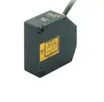
Sensor Controller, 24 VDC, PNP Outputs
- Manufacturer: OMRON INDUSTRIAL AUTOMATION
- Product type:
- SVHC: To Be Advised
| Delivery and price | |
|---|---|
| Units per pack | 1 |
| Price | 2772.69 € |
| Current stock | 10+ |
| Lead time | 30 days |
Smart Sensors 2s series ——<——— **==> picture [17 x 23] intentionally omitted <==** **----- Start of picture text -----**<br> ¥<br>**----- End of picture text -----**<br> 2D CMOS Laser Type High-precision Displacement Measurement Sensors Bringing Smart Sensors into New Fields. ——————— = Peres : ———— ——= — y Ges EG = === 5 Neon SS ———_ Soa ——————essssssssssssSsm lc te BY Bo ge SS — —SS—= PQ|||"eee **a** lla ee¢ ee2i d LEE———————sey,= 2— —. etree+ , COE(eoyyeG fog) uod I=ane,(fonspsWe ~ ut aaU5 PuyHeSSin.ie ey 20ie ENABLE* )‘ | l = , e — ; ee. See aoa Il — r“hbs er aeee f es—— . a~ StaSGarSi eee= SS| EllePek e) ] TYG p 1 ellpaged i —_ + oa : : x — SS!)SS ay ZA A. : 7 = C = a — 25-og OF _ AS S = — - fee ‘ SOOO . = 6 ——————————— ## ZS-HL Series ## More P.6 ## Very High-performance Sensors that Support Core Quality from Very Long-range to Extremely Precise Measurements Range of models with measuring center distance of 20 to 1,500 mm. Achieves maximum resolution of 0.25 m. Maximum response speed of 110 s. Parallel output supported. **==> picture [432 x 318] intentionally omitted <==** **----- Start of picture text -----**<br> ; oa_-< ZS-HLDS150<br>as<br>1500<br>See<br>ZS-HLDS60<br>600 ZS-HLDS10<br>ZS-HLDS5T ZS-LD10GT/LD15GT<br>ZS-HLDS2T* ZS-HLDS2VT<br>f <I<br>Se<br>| =<br>100<br>15±0.75mm<br>25±2mm 10±0.5mm<br>20±1mm<br>50<br>50±5mm<br>20 100±20mm * Orders will be accepted until the end of August 2019.<br>15 600±350mm<br>10 1500±500mm<br>Measuring center distance<br>**----- End of picture text -----**<br> ## Record ## Data Storage Unit ZS-DSU ZS-DSU ## Ideal for ZS Series Data Logging Enables onsite high-speed logging of data in external memory (compact flash card) for the Sensor Controller or Multi-Controller. Effective for building traceability systems, statistical process control (SPC), and much more. High-speed sampling rate: 150 µs Powerful support for logging data using various trigger functions. **==> picture [57 x 9] intentionally omitted <==** **----- Start of picture text -----**<br> More P.18<br>**----- End of picture text -----**<br> ## Control Multi-Controller ZS-MDC Enables full application of Sensor Controller information. Transfers data between multi-connected Sensor Controllers and performs high-speed multiprocessing. Connects to up to nine Sensor Controllers. More P.17 02 ## SS ———————————nnn **Smart Sensor** ~~EEssa~~ Advanced technology is carried ## nctions in a Compact Package **==> picture [101 x 192] intentionally omitted <==** **----- Start of picture text -----**<br> Business card size<br>i n B s<br>USB<br>Monitor<br>+XX-XX-XXX-XXX +XX-XX-XXX-XXX<br>**----- End of picture text -----**<br> ## Manipulate ## Sensor Controllers ZS-HLDC/LDC ## SmartMonitor Enable maximum sensing performance with fully digital processing. ## Professional ZS-SW11E V3 Setting Software for the ZS Series Culmination of OMRON's lead-edge digital technology. Enables easy utilization of the ultimate in measurement performance. Meets a wide range of logging needs. Supports high-speed simultaneous multichannel waveform graphs. ## Business card size USB provided as a standard feature. Excel macros provided for simple analysis. More P.12 More P.19 ## ZS-L Series ## More P.14 Standard Sensors Most Suitable for a Variety of High-precision Displacement Measurements, Including Spot Detection, Wide-range Detection, and Long-distance Detection. **==> picture [161 x 38] intentionally omitted <==** **----- Start of picture text -----**<br> Beam Shapes<br>Spot and line beam selection.<br>Wide Range of Products<br>Long-range, middle-range, and short-range models.<br>**----- End of picture text -----**<br> **==> picture [300 x 296] intentionally omitted <==** **----- Start of picture text -----**<br> Measuring<br>center distance Diffuse Reflective Sensors<br>ZS-LDC<br>350 ZS-LD350S Regular Reflective Sensors<br>200 ZS-LD200<br>130<br>ZS-LD130<br>80 ZS-LD80<br>50<br>40<br>ZS-LD50/LD50S<br>20<br>ZS-LD40T<br>ZS-LD20T/LD20ST<br>Spot beam<br>Line beam<br>Line beam<br>Line beam<br>Line/spot beam<br>Line beam<br>Line/spot beam<br>**----- End of picture text -----**<br> 03 ## Main Applications ## **High Performance** Very High-performance Sensors that Support Core Quality from Very Long-range to ZS-HL Series Extremely Precise Measurements **ZS-LD10GT/LD15GT ZS-HLDS2T* ZS-HLDS2VT ZS-HLDS5T ZS-HLDS10 ZS-HLDS60 ZS-HLDS150** <} 3 - q | », a. J >-0 JL al | Me”, 7 - i P ) Sealer coating ) .. Glass substrate \ % | @ 7 ) S a Ideal for measuring Ideal for measuring Ideal for measuring Ideal for measuring Ideal for confirming Ideal for level Protruding objects and and controlling the thickness of the potting resin height liquid gasket (FPIG) positioning and detection for liquid steps can be measured dispenser nozzle gaps silicone or compound for electronic application amounts. repeatability accuracy crystal coaters and from a distance for semiconductor wafers when applying sealer. components. Prevents defects such of XY stages. PDP fluorescent measurement objects in polishing and testing as insufficient seal. substances. that cannot be processes. accessed easily. - Orders will be accepted until the end of August 2019. **Standard** ZS-L Series Standard Sensors Ideal for a Variety of High-precision Displacement Measurements, Including Spot Detection, Wide-range Detection, and Long-distance Detection ## **ZS-LD20ST** **==> picture [51 x 10] intentionally omitted <==** **----- Start of picture text -----**<br> ZS-LD40T<br>**----- End of picture text -----**<br> **==> picture [77 x 10] intentionally omitted <==** **----- Start of picture text -----**<br> ZS-LD50/LD80<br>**----- End of picture text -----**<br> **==> picture [51 x 10] intentionally omitted <==** **----- Start of picture text -----**<br> ZS-LD200<br>**----- End of picture text -----**<br> **==> picture [58 x 10] intentionally omitted <==** **----- Start of picture text -----**<br> ZS-LD350S<br>**----- End of picture text -----**<br> 3D shape measurement using automatic X-Y stage Ideal for measurements requiring discrimination between minute parts or fine shape repeatability. Ideal for measuring glass Ideal for measuring the thickness and nozzle warp of resin blades in gaps when coating glass copy machine toners. with resist or sealer. Ideal for checking the Ideal for checking the precision of door flatness of robot arms installations. that transport wafers in load ports. 04 ## **Smart Sensor** ## Applications by Industry ## Automobile and Automotive Parts **==> picture [332 x 9] intentionally omitted <==** **----- Start of picture text -----**<br> Measuring Car Bodies Measuring Door Attachment Offsets Measuring Tire Exteriors<br>**----- End of picture text -----**<br> ## Semiconductors **==> picture [335 x 14] intentionally omitted <==** **----- Start of picture text -----**<br> Measuring Electrode Thicknesson Compound Semiconductors Measuring Wafer Warping and Thickness Measuring Arm Inclination<br>**----- End of picture text -----**<br> ## LCDs and PDPs **==> picture [335 x 9] intentionally omitted <==** **----- Start of picture text -----**<br> Measuring Glass Undulation Measuring Glass Surfaces Inspecting Glass Heights (Autofocus)<br>**----- End of picture text -----**<br> ## Electronic Components **==> picture [335 x 84] intentionally omitted <==** **----- Start of picture text -----**<br> Measuring Shape for<br>Inspecting Board Heights Inspecting for Board Coplanarity Positioning Laminated Ceramics<br>1 axis scan<br>Capacitor<br>PCB<br>SmartMonitor graph screen<br>Spot beam<br>Line beam<br>**----- End of picture text -----**<br> ## Household Appliances and Audio-visual **==> picture [336 x 15] intentionally omitted <==** **----- Start of picture text -----**<br> Simultaneous Measuring of Touch Panel Film Thickness and Gap DVD Chassis Flatness Inspections Digital Camera Tube Lens Inspection<br>**----- End of picture text -----**<br> ## Rubber, Resin, and Film **==> picture [324 x 13] intentionally omitted <==** **----- Start of picture text -----**<br> Measuring Electrode<br>Thickness on Dielectrics Moving Workpieces (Black Rubber) Measuring Depth of O-Ring Insertion<br>**----- End of picture text -----**<br> 05 e ~~fe~~ _**H i g h g r a d e**_ ## ZS-HL Series Product Lineup 2D CMOS High-end Displacement Sensors Advanced sensing technology packed into the best Sensor Head for the highest sensing precision Wide lineup of products from 0.25 m high-resolution models to 1,500 mm long-range models. ## **ZS-HLDS150** ## **ZS-HLDS60** ## **ZS-HLDS10** ## **ZS-HLDS5T** ## **ZS-HLDS2T*** ## **ZS-HLDS2VT** ## **ZS-LD10GT/LD15GT** Model Measuring center distance 1500±500 mm 600±350 mm 100±20 mm 50±5 mm 20±1 mm 25±2 mm Resolution 500 m 8 m 1 m 0.25 m 0.25 m 0.6 m 0.25 m Linearity ±0.2%F.S. ±0.07%F.S. ±0.1%F.S. ±0.1%F.S. ±0.05%F.S. ±0.2%F.S. ±0.1%F.S. Beam shape 1.5 mm × 40 mm 0.3 mm × 16 mm 60 m × 3.5 mm 30 m × 1 mm 20 m × 1 mm 45 m × 2.2 mm 25 m × 900 m ~~i?) |0LlULUlLlUlULlUClClU~~ 20±1 mm 25±2 mm 10±0.5 mm /15±0.75 mm 0.25 m 0.6 m 0.25 m * Orders will be accepted until the end of August 2019. 06 | ## **Smart Sensor** ## All Models Are Class 2 Lasers. ## Digital Sensing Totally reliable measurements with completely digital sensing. ## Extreme Stability ## Ideal Size and Stability Head Size Complete sensing stability with optimum Sensor Head size for best performance and holding mechanism secured at 3 points. (See note.) **==> picture [180 x 125] intentionally omitted <==** **----- Start of picture text -----**<br> ZS-HLDS60/HLDS150<br>ZS-HLDS2T* ZS-HLDS5T/<br>HLDS10<br>Note: ZS-HLDS2T not applicable.<br>* Orders will be accepted until the<br>end of August 2019.<br>**----- End of picture text -----**<br> ## 2D CMOS Laser Image Sensing Element The three basics of sensing - precision, speed, and sensitivity - can be balanced because ideal measurement settings can be made for light reception area. ±0.05% FS Linearity ## (ZS-HLDS2T)* Unique OMRON algorithms reduce detection error to improve workpiece measurement accuracy. * Orders will be accepted until the end of August 2019. ## Extremely Sensitive Lenses ## Superior Moving Resolution Increased Lens Resolution Moving resolution (error based on workpiece surface position) has been reduced dramatically by optimizing the optical system with increased sensitivity and resolution of the light receiving lenses. **==> picture [217 x 134] intentionally omitted <==** **----- Start of picture text -----**<br> 10 Moving resolution when measuring SUS<br>5 oo 13.5 m<br>0 1000 2000 3000 4000 5000 6000<br>0<br> 5<br>Constant<br> 10 distance<br>Travel distance<br>SUS<br>10 Moving resolution when measuring SUS ZS-HLDS5T<br>5<br>4.5 m<br>0<br> 5 0 500 1000 1500 2000 2500 3000<br> 10<br>Travel distance<br>Sampling: 4 ms<br>m) Measurement value ( <br>Previous OMRON models<br>m) <br>ZS-HL Series Measurement value (<br>**----- End of picture text -----**<br> High Resolution at 0.001 m (ZS-LD10GT) OMRON's digital sensing technology achieves unbelievably high resolution. Super-high-speed Sampling at 110 s (ZS-HLDS@@/LD@@) You get exact sensing with superior workpiece following performance. CMOS high-speed data reading accurately catches moving workpieces inline. ## Reduced Error for Different Materials 2D CMOS With a CCD, the charge overflows to the next pixel when excessive light is received. This phenomenon does not occur with CMOS, so there are no effects from light fluctuations from different materials or excessive light reception. **==> picture [212 x 134] intentionally omitted <==** **----- Start of picture text -----**<br> Previous OMRON models<br>50 Eo Cr Glass 10 mp-p<br>5<br> 10<br> 15 distanceTravel Constant<br>0 20 40 (mm) distance<br>ZS-HLDS5T Cr Glass<br>10<br>Cr Glass<br>5 0.7 mp-p<br>0<br> 5 | | ft | Travel<br> 10 |=| 0 20 40 distance(mm)<br>Sampling: 4 ms<br>m) Error ( <br>Previous OMRON models<br>m) <br>ZS-HL Series Error (<br>**----- End of picture text -----**<br> 07 © ## **ZS-HLDS5T/HLDS10** ## Detect Essentially Any Object Reduced Variation in Linearity between Different Objects, and Linearity Determines Measurement Accuracy. Makes it easier to introduce a variety of detection objects. **==> picture [115 x 127] intentionally omitted <==** **----- Start of picture text -----**<br> Model ZS-HLDS5T<br>Measuring center distance 50±5 mm<br>Resolution 0.25 µm<br>Linearity ±0.1%F.S.<br>Beam shape 30 µm × 1 mm<br>Model ZS-HLDS10<br>Measuring center distance 100±20 mm<br>Resolution 1 µm<br>Linearity ±0.1%F.S.<br>Beam shape 60 µm × 3.5 mm<br>**----- End of picture text -----**<br> Measuring Car Body Widths (ZS-HLDS10) ## Linearity Characteristic **==> picture [489 x 131] intentionally omitted <==** **----- Start of picture text -----**<br> Previous OMRON models Regular reflection ZS-HLDS5T Regular reflection<br>0.15 0.15<br>0.10 0.10<br>0.05 0.05<br>0.00 0.00<br>−0.05 40.0 42.0 44.0 46.0 48.0 −0.05 40 42 44 46 48<br>−0.10 −0.10<br>−0.15 −0.15<br>Measuring range (mm) Measuring range (mm)<br>Sample-A Sample-B Sample-C Sample-D Sample-E No.1 No.2 No.3 No.4 No.5 Note: Typical examples Manage trends by measuring<br>widths of each car model.<br>Linearity (% F.S.) Specified range Linearity (% F.S.) Specified range<br>**----- End of picture text -----**<br> ## **ZS-HLDS60/HLDS150** ## A Long Range That Handles Essentially Any Installation Site First 1,500 mm long range sensing in the industry enables measurement of previously impossible points. ## Simple Long-distance Step Measurement **==> picture [432 x 125] intentionally omitted <==** **----- Start of picture text -----**<br> Model ZS-HLDS60<br>Measuring center distance 600±350 mm<br>Resolution 8 µm Peak<br>Linearity ±0.07%F.S. Bottom<br>Beam shape 0.3 mm × 16 mm<br>Peak<br>Model ZS-HLDS150 x. = Bottom<br>Measuring center distance 1500±500 mm<br>Resolution 500 µm<br>Linearity ±0.2%F.S.<br>Beam shape 1.5 mm × 40 mm<br>**----- End of picture text -----**<br> Peak/bottom measurement Note: This function may not be applicable in bright surrounds. 08 ## **Smart Sensor** **ZS-HLDS2VT** Ideal for Measuring the Height and Thickness of Transparent Objects Tilted and moving workpieces can also be stably measured. A special aspherical lens was l, developed for the ZS-HLDS2VT, and the design of the optical structure was optimized for regular-reflective workpieces. This has greatly increased the Model **ZS-HLDS2VT** allowable degree of tilt and Measuring center distanceResolution 25±2 mm 0.6 µm improved stability for measuring Linearity ±0.2%F.S. transparent and regularAspherical lens (newly developed) Beam shape 45 µm × 2.2 mm reflective workpieces. Angle Characteristics 6 5 4 3 ~~.~~ 2 ~~8~~ 1 0 Previous OMRON model ZS-HLDS2VT Vertical Horizontal direction direction Vertical + direction Vertical - direction Horizontal + direction Horizontal - direction 09 ~~ee~~ _**H i g h g r a d e**_ ## **ZS-HLDS2T*/ZS-LD10GT/LD15GT** ## The Only Way to Very High-precision Measurements ## Superior Features for Semiconductor Wafer, Glass, and Other Measurements Requiring Precision **==> picture [521 x 162] intentionally omitted <==** **----- Start of picture text -----**<br> Simultaneous Measuring of Touch Panel Film Thickness and Gap<br>100<br>95<br>90<br>85<br>80<br>Model ZS-HLDS2T* 75<br>70<br>Measuring center distance 20±1 mm<br>65<br>Resolution 0.25 µm Thickness 60<br>0 0.2 0.2 0.4<br>Linearity ±0.05%F.S. Film<br>Beam shape 20 µm × 1 mm Glass = H Gap<br>* Orders will be accepted until the end of<br>August 2019.<br>Slim<br>26.4 mm<br>m]<br>µ<br>Thickness [<br>**----- End of picture text -----**<br> **==> picture [292 x 87] intentionally omitted <==** **----- Start of picture text -----**<br> 100 400<br>95 350<br>90 300<br>85 250<br>80 200<br>75 150<br>70 100<br>65 50<br>60 0<br>0 0.2 0.2 0.4 0.6 0.8 1 0 0.2 0.4 0.6 0.8 1<br>Travel distance (mm) Travel distance (mm)<br>m]<br>µ m]<br>µ<br>Gap [<br>Thickness [<br>**----- End of picture text -----**<br> Simultaneous measurement of transparent object thickness and gap ## An unbelievable stationary measurement precision of 0.25 µm, the highest in this product class. Ideal for Measuring Nozzle Gaps! Height Control of Sealant Dispensers Inspection of Disk Play on HDD Motor Rotating Plate Reduced pattern influence for moving measurement, the best in the moving resolution industry. **==> picture [172 x 119] intentionally omitted <==** **----- Start of picture text -----**<br> ZS-LD10GT<br>2<br>1 Po<br>0 AAAAAAAAA A A<br>-1<br>-2 WAA A A<br>-3 HLTALT AT<br>-4<br>TO<br>-5<br>1 251 501 751 Number<br>of data<br>Measures amplitude undulations of 5 µm.<br>TA<br>m]Displacement [µ<br>**----- End of picture text -----**<br> > : Possible to match nozzle drip point and Sealant supply nozzle measurement point then measure. . Sensor Head with separate light emission ———— ZS-LD10GT/LD15GT and reception in one unit to create nozzle space. . , > Nozzle Gap Sensor iy << sw j&_= > Model **ZS-LD10GT/LD15GT** > Nozzle / ty -- \ > Measuring center distance 10±0.5 mm/15±0.75 mm Sealant application Glass substrate Resolution 0.25 µm Linearity ±0.1%F.S. Emitter Receiver Measurement ~~———~~ Beam shape 25 × 900 µm point 10 ©) ## **Smart Sensor** ## **Technology** With OMRON's sensing technology and newly developed algorithms, stable, high-precision measurement is possible of workpieces that were difficult to measure using laser displacement meters due to laser light penetration, transmission, excessive reflection, or insufficient light. Mechanisms for Stable Measurement Patent Pending Mechanisms for Stable Measurement Patent Pending CC ~~A~~ es No more errors due to reflection No more errors due to workpiece coefficients between glass gaps reflection coefficients. **==> picture [374 x 270] intentionally omitted <==** **----- Start of picture text -----**<br> Stable measurement by adding received light Stable measurement using laser power algorithms<br>waveform in 2D image and digital zoom that can be adjusted to any value.<br>processing.<br>Mirror (Large) Small (Black rubber)<br>Reflection coefficient<br>Previous Light noise Large 10,000 levels min. (essentially infinite)<br>products Detects the measurement position No measurement error<br>for each received light line.<br>ZS Series 31 levels<br>Measurement error<br>Previous products<br>Small Sensitivity<br>Detects the measurement switching<br>position after adding the<br>ZS Series received light lines.<br>Removed Light quantity adjustment algorithms have<br>Position evolved for stable measurement of a variety of<br>measurement objects.<br>Then with digital processing... Even if the workpiece status changes<br>ZS-HL Series<br>suddenly, the sensitivity can compensate at<br>any level so there is no measurement error<br>from sensitivity switching.<br>One line at a time Received light amount Laser power<br>Adding and averaging Received light amount<br>**----- End of picture text -----**<br> Measurement cycle time 1/8 better than previous models with addition of received light waveform captured by 2D CMOS and simultaneous measurement of front and back glass surfaces with separate sensitivities. Mechanisms for High Resolution Patent Pending Mechanisms for Stable Measurement | i ( i ll SS rrri‘(‘COOCsS No more resolution errors. No more error due to penetration. Stable measurements are achieved by correctly recognizing the light reception distribution on the 2D CMOS. **==> picture [355 x 220] intentionally omitted <==** **----- Start of picture text -----**<br> Digital processing technology between the Stable measurements are achieved by correctly<br>Sensor and Controller provides high resolution. recognizing the light reception distribution on the<br>Digital communications 2D CMOS.<br>| _—<br>(2)<br>(3)<br>(1)<br>(Near)<br>(Far)<br>Laser Pulse Control<br>Light quantity adjustment to any level.<br>80 ns min. Large Previous products Large Real peak position on surface<br>Light quantity<br>fluctuation error Incorrect peak<br>(1)Received Light Signal Control Error between clocks calculation as a result of laser light penetration<br>No clock offset. No error<br>(2)(3) Small(Near) Received light surfaceZS Series(Far) Received light waveform disruption due to penetration<br>Small<br>(Near) Received light surface (Far)<br>Received light amount<br>Received light amount<br>**----- End of picture text -----**<br> High-speed digital communications (LVDS) used between Sensor and Controller. Image signal stabilizes because the clock error between the control signal from the Controller and the light reception device disappears. Optimum light quantity adjustment is possible with laser power algorithms that can be adjusted to any level, which facilitates super high resolution. Real surface displacement detected by eliminating penetration effects for PCBs, plastic, and other workpieces penetrated by laser light. 11 > ## Sensor Controllers **ZS-HLDC**[ (Multitasking)] Enables maximum sensing performance with fully digital processing and multitasking functions. A controller the size of a business card filled with OMRON's leading-edge digital technology. Enables easy utilization of the ultimate in measurement performance. Simultaneous Measurement and Output of Up to 4 Features **==> picture [381 x 154] intentionally omitted <==** **----- Start of picture text -----**<br> When simultaneous For detection of small<br>measurement of distance to recesses and protrusions in<br>glass, glass thickness, gap, etc., measurement location<br>required in glass measurement Setting example Enlarged<br>applications ■ Task 1: Step<br>Setting example<br>■ Task 1: Average For measurement of steps in<br>■ Task 2: Thickness different locations with<br>For simultaneous measurement moving Sensor or workpiece<br>of HDD surface deflection and Setting example<br>distance to HDD surface ■ Task 1: AverageSelf-down trigger Trigger level<br>Setting example Average hold<br>■■ Task 1: Average, Average holdTask 2: Average, Point-to-point hold ■ Task 2: AverageWith delay Delay time 1<br>Average hold Delay time 2<br>With delay<br>■ Task 3: Calculation (Task 2 - Task 1)<br>**----- End of picture text -----**<br> Simultaneous Control in 2 Systems of Data Confirmation and Analysis and Data Collection, Control, and Changeovers ## Outline of Functions **==> picture [220 x 77] intentionally omitted <==** **----- Start of picture text -----**<br> ZS-HLDC ZS-LDC<br>Top Operation Menu<br>Multitask Mode Single Task Mode (Standard Mode)<br>Sensing TASK1 TASK2 TASK3 TASK4 I/O Settings Sensing TASK1 I/O Settings<br>Measurement point Filter Output Filter Output<br>**----- End of picture text -----**<br> ## Control Using CompoWay/F* **==> picture [93 x 31] intentionally omitted <==** **----- Start of picture text -----**<br> Data Confirmation and<br>Analysis<br>• Checks sensing screen.<br>**----- End of picture text -----**<br> - Checks measurement values. - Logs measurement values. - OMRON's unique communications protocol. **==> picture [63 x 6] intentionally omitted <==** **----- Start of picture text -----**<br> USB RS-232C<br>**----- End of picture text -----**<br> Control Using No-protocol Communications **==> picture [89 x 20] intentionally omitted <==** **----- Start of picture text -----**<br> Data collection, control,<br>and changeovers<br>**----- End of picture text -----**<br> **==> picture [88 x 6] intentionally omitted <==** **----- Start of picture text -----**<br> • Gets measurement results.<br>**----- End of picture text -----**<br> - Resets to zero. **==> picture [65 x 6] intentionally omitted <==** **----- Start of picture text -----**<br> • Switches banks.<br>**----- End of picture text -----**<br> Improved Total Cycle Time with 1-second High-speed Bank Switching 12 ## **Smart Sensor** ## Information at the Touch of a Button In RUN (measurement) Mode, measured values and information are displayed using 2 rows of 8-segment LEDs. The large LED display improves visibility. Measurement information includes the threshold, current, resolution, and received light amount and is available with simple key operations. LCD screens can be customized to change the display of desired information to easier-to-understand terminology. RUN (measurement mode) Measured value displayed. Example of Display Customization Threshold, current, resolution, received light amount, etc. Device: MAIN:MEASURE OMRON #1 SUB :THRESH Switch measurement information at the touch of a button. ## Set Sensing Directly In FUN (setting) Mode, setting menus are displayed on the 2 rows of the LCD. Easy-to-understand guidance simplifies setting the many display capabilities of the LCD. Function keys correspond to displayed menu items for intuitive setting of measurement conditions and other parameters. You can also easily switch between Japanese and English displays. Communication with the operator is better than ever before. **==> picture [69 x 56] intentionally omitted <==** **----- Start of picture text -----**<br> eases<br>**----- End of picture text -----**<br> **==> picture [69 x 8] intentionally omitted <==** **----- Start of picture text -----**<br> FUN (setting mode)<br>**----- End of picture text -----**<br> Direct setting with function keys. **==> picture [230 x 28] intentionally omitted <==** **----- Start of picture text -----**<br> MAIN:MEASURE MAIN:MEASURE MAIN:MEASURE LD POWER 80.0%<br>SUB :THRESH SUB :CURRENT SUB :RESOLU SUB:BRIGHT<br>Threshold Se Current ©S® Resolution G®@ Received light<br>amount<br>**----- End of picture text -----**<br> Mount to DIN Track or directly to control panels. Patent Pending — a Connect directly to a PC using USB. USB 2.0 and RS-232C provided as standard features. LVDS, a new-generation digital high-speed communications interface, is used between the Sensor Head and Controller, an industry first. If USB is used to connect to the computer, high-speed all digital USB Connection measurement data transfer is possible. Firmware can be updated easily using the SmartMonitor WarpEngine. ## **ZS-LDC** Single Task Controller Simple Operation Reasonable Price Panel Mounting Adapter (Option, Sold Separately) 13 ZS-L Series Product Lineup 2D CMOS Low-end Displacement Sensors Advanced sensing technology packed into the smallest Sensor Heads in this class. Smallest size in this class (65 × 65 mm) Uniform Sensor Head size Line/spot beam type Detects black rubber, mirror, and transparent workpieces **==> picture [756 x 390] intentionally omitted <==** **----- Start of picture text -----**<br> ZS-LD50/LD80/LD130/LD200/LD350S<br>Line/spot beam type<br>Detects black rubber, mirror, and transparent workpieces<br>2D CMOS<br>image sensor<br>Super Sensitive Lens<br>Note: The ZS-LD50 uses<br>Laser Class 2 high-precision<br>Degree of Protection: IP67 ganged lenses.<br>(Models with 2 m cable)<br>ZS-LD20T/LD40T ZS-LD20ST/LD50S<br>ZS-LD50 Measurement range: 10 mm Spot Beam Sensors<br>Measuring center: 50 mm<br>Measurement range: 30 mm<br>ZS-LD80 2D CMOS<br>Measuring center: 80 mm image sensing<br>element<br>High-precision<br>Measurement range: 30 mm<br>ganged lenses<br>ZS-LD130 Laser Class 2<br>Measuring center: 130 mm Degree of Protection: IP67<br>(Models with 2 m cable) Diffuse Reflection Sensors<br>ZS-LD50S<br>Measuring center: 50 mm<br>Line beam<br>ZS-LD20T (900 × 25 μ m) Measurement range:<br>Measurement range: 100 mm Measuring center: 20 mm 2 mm<br>ZS-LD200 Resolution: 0.25 μ m<br>Measuring center: 200 mm Measurement range: Spot beam<br>10 mm (50 μ m dia.)<br>More than<br>sufficient<br>range Line beam Measurement range:<br>ZS-LD350S ∗ 1 Measurement range: 270 mm Measuring center: 40 mmZS-LD40T (2000 × 35 μ m) 5 mm Measuring center: 20 mmZS-LD20ST Regular reflection Sensors<br>Measuring center: 350 mm Resolution: 0.4 μ m<br>∗ Note: Sensor Head can be installed to for either 1. Spot Beam Sensors. Measurement range: 2 mm Spot beam (25 μ m dia.)<br>diffuse reflection or regular reflection.<br>(except ZS-LD350S) Correctly compensates measurement values to suit different applications. Diffuse Reflection Sensor Regular Reflection Sensors<br>**----- End of picture text -----**<br> 14 SS —_________ **Smart Sensor** Advanced technology is carried Line Beam Sensors for Emphasis Spot Beam Sensors Ideal for Minute on Stable Measurement Workpieces and Shape Measurement ## Stable Measurements for PCBs, Black Resin, and Metal a All you need to do is select the proper mode to achieve stable sensing of PCBs, resins, black on Stable Measurement rubber, and other light-penetrating workpieces (these could not be easily handled with previous reflective laser displacement meters.) Line beams produce an averaging affect that is Line beams produce an averaging affect that is less likely to be affected by surface irregularities, creating stable measurements. Ideal for measurements requiring minute shape repeatability while matching laser beam position with a minute target measurement area. ## **ZS-LD80** **==> picture [751 x 193] intentionally omitted <==** **----- Start of picture text -----**<br> Gain setting: 5<br>Measuring the Shape of Black Resin Workpieces 15.000 Ideal for stable measurements that do not rely on measurement area.<br>10.000 0 the surface of the target workpiece.<br>= 5.000 10<br>= ie, 0.000 r = 5 = =aSiI | oo 20 , Travel —> |! —_— Travel<br>30<br>−5.000<br>40<br>−10.000<br>−15.000<br>Complete measurement data will be obtained at angles of up to 40°. Number of data a Travel distance Amount ofdisplacement . Beam diameter Travel distance Amount ofdisplacement<br>ZS-LD50 Beam width Beam diameter<br>Response: 8 ms, High-precision mode,<br>Measuring the Shape PCB Surfaces 1.75 Black gain: 0, Red gain: 5 (max.) Line Beam sensors ZS-LD20T ZS-LD40T ZS-LD50 ZS-LD80 ZS-LD130 ZS-LD200<br>1.73 Beam diameter 25 μm 35 μm 60 μm 60 μm 70 μm 100 μm Spot Beam sensors ZS-LD20ST ZS-LD50S ZS-LD350S<br>1.71 Beam width 0.9 mm 2 mm 0.9 mm 0.9 mm 0.6 mm 0.9 mm Beam width 25 μm dia. 50 μm dia. 240 μm dia.<br>1.69<br>1.67<br>1.65<br>Penetration mode and gain settings used.<br>Height (mm)<br>Height (mm)<br>**----- End of picture text -----**<br> ## Easy Sensing with an HMI That Couldn't Be Easier to Use PCB shapes can be measured without burs or waveform disruptions. Just select High-precision Mode to stably measure black rubber. Just select Penetration Mode to stably measure PCBs or black resin. ## Stable Measurements for Glass ## Set Sensing Directly - Stably measure height and undulations in transparent, coated, or colored glass on work tables. Stable detection at 40 mm with a line beam of 2 mm. **==> picture [140 x 75] intentionally omitted <==** **----- Start of picture text -----**<br> FUN (setting mode)<br>Direct setting with<br>function keys.<br>**----- End of picture text -----**<br> - A 2-mm line beam reduces the influence of black and white patterns on granite work tables to achieve stable measurements. ## **ZS-LD40T** **==> picture [283 x 83] intentionally omitted <==** **----- Start of picture text -----**<br> Measurements for Moving Glass<br>Measuring Glass Surfaces [μ4m] Response for glass 8 ms<br>3<br>2<br>1<br>0<br>−1<br>−−23 0.2 μm<br>−4<br>**----- End of picture text -----**<br> Ideal for measuring glass thickness and slit nozzle gaps when coating glass with resist or sealer. 15 ## System Configuration **==> picture [702 x 404] intentionally omitted <==** **----- Start of picture text -----**<br> Sensors Controllers Peripheral Devices<br>Parallel I/O<br>ZS-HL Series Sensor Controllers<br>Expansion I/O Units<br>PLC<br>| ely a<br>| a a: Multi-Controllers Data Storage High-speed Input Boards (PC) SF<br>— — od = Units a ee Le<br>| = USB<br>at ZG-RPD<br>‘= — = |<br>Cinemasa High-speed =i —<br>ZS - HLDC «1 binaryof measurement output data. «3 | c mEa" ¥:<br>ZS-L Series SS<br>SmartMonitor (PC)<br>ZS-SW11V3E<br>RS-232C<br>ZS-MDC ZS-DSU<br>; ~ ~ | om PLCs etc.<br>Calculating measurement Log measurement Values.<br>: results for each sensor.<br>Tn r— > CompoNet<br>- r<br>ms<br>-, OMRON tt oe 4 ray A<br>=, ) EE<br>he PLCs etc.<br>*1: The ZS - HLDC can be connected to a ZS -H L/L -s eries Sensor Head. ZS-CRT Sensor Communications Unit<br>*2:*3: TheThe ZGZS -- LDCRPD canExpansionbe connectedI/O Unitonlycantobea connectedZS -L-s eriesonlySensorto a ZSHead. -H L- s eries Sensor Controller. Connection Cable oe Analog<br>ZS-HL-series Long-distance Extension Cable ZS-XC02D<br>25 m max.<br>_— Flexible Long-distance Extension Cable ca aT!St—— Data logger etc.<br>ZS - XEQ ZS-XC15CR/XC25CR a .<br>Sensor Head Digital Equalizer +4 Digital Equalizer Controller aE:<br>ZS-HLDS@ ZS - XEQ #4 ZS-HLDC@<br>**----- End of picture text -----**<br> 16 ## **Smart Sensor** ## Multi-Controller **ZS-MDC** ## Centralized Controller Information Calculations Transfers data between multi-connected Controllers and performs high-speed multiprocessing. ## High-speed Connections for Up To 9 Controllers See the difference in applications requiring multipoint measurement, such as thickness, steps, and flatness measurements. Connect up to 9 Controllers with the fastest high-speed bus in the industry. Digital processing prevents data dropouts to provide the capability to measure exactly what is seen. Sampling speed with 3 Controllers connected: 110 μ s, Sampling speed with 9 Controllers connected: 380 μ s Note: When using communications commands. **==> picture [371 x 94] intentionally omitted <==** **----- Start of picture text -----**<br> Sensor Head Multi-Controllers SmartMonitor<br>Monitor connected Controllers<br>together<br>USB<br>Multipoint measurement ZS-MDC Processing results<br>(flatness of resins or metals)<br>**----- End of picture text -----**<br> ## Processing Enabled by the Multi-Controller **==> picture [712 x 175] intentionally omitted <==** **----- Start of picture text -----**<br> Flatness Calculations Reference Step Calculations Relative Step Calculations Twisting Calculations<br>Calculating the difference between the Calculating the difference between a Calculating the difference between all points. Calculating twisting between opposing sides.<br>maximum and minimum values. reference point (A) and other points.<br>Calculation: Task 1 = Max. (A, B, ···) A C B Number of Sensor Controllers: 3 to 9 − Min. (A, B, ···) A C B Number of Sensor Controllers: 3 to 9Calculation:Individual judgmentsTASK1 = A TASK2 = A −− B C··· A C B Individual judgmentsNumber of Sensor Controllers: 3 to 9Calculation:TASK1 = A TASK2 = B TASK3 = C −−− B C A B Calculation: TASK1 = (A A C D Number of Sensor Controllers: 4 − B) − (D − C)<br>Multipoint Thickness Calculations Average Height Calculations Warp Calculations User-set Calculations Multi-calculations of Data<br>Calculating the difference between pairs of points. Calculating the average surface height. Calculating warping of selected sides Formulas can be flexibly set.<br>Number of Sensor C<br>A C E Controllers: 2, 4, 6, or 8Calculation: A C B Number of Sensor A B Number of Sensor Multipoint measurement<br>TASK1 = K TASK2 = K −− (A + B) (C + D) Controllers: 2 to 9 Controllers: 3 [K + mX + nY]<br>— B D F Individual judgmentsTASK3 = K − (E + F) Calculation: Task 1 = Average (A, B, C, ···) Calculation: Task 1 = B − (A + C)/2 High-speed data transfer<br>cee ee ae a<br>**----- End of picture text -----**<br> 17 O ## Data Storage Unit **ZS-DSU** Logging Software for Onsite Installed Efficiently stores sensing data using a variety of logging functions. High-speed, long term logging settings can be used to precisely process the required sensing data, which can be reliably and completely collected using USB and an all-digital bus. Sensor setting data can also be stored. Data for up to 128 banks can be stored and transferred to the Master Unit for changeovers. ## High-speed sampling rate: 150 μs max. Powerful support for logging data using various trigger functions. Multipoint data collection Traceability Changeover Unit |Config-||Number of<br>connectable Controllers|Number of<br>connectable Controllers|Number of<br>connectable Controllers|10 max. (ZS-MDC: 1, ZS-HLDC/LDC: 9 max.)|10 max. (ZS-MDC: 1, ZS-HLDC/LDC: 9 max.)|10 max. (ZS-MDC: 1, ZS-HLDC/LDC: 9 max.)|||||||| |---|---|---|---|---|---|---|---|---|---|---|---|---|---|---| |uration||Connectable Controllers|||ZS-HLDC@, ZS-LDC@, ZS-MDC@|||||||||| ||||Data resolution||32 bits|||||||||| |Perform-|||||•Shortest high-speed logging mode (One-shot Mode)|Shortest high-speed logging mode (One-shot Mode)∗1||||||||| |ance|||Sampling rate||•Long-term logging mode (Repeat Mode)|Long-term logging mode (Repeat Mode)∗2||||||||| ||||||•Sampling period: 10 ms to 1 h (at 1-ms intervals)|Sampling period: 10 ms to 1 h (at 1-ms intervals)|||Data Storage Unit|||Sensor Controller||Sensor Controller| ||||||||||(ZS-DSU)|||(ZS-LDC)||(ZS-LDC)| ||||||Start and end triggers can be set separately.|||||CF Card||||| ||||Trigger functions||External trigger/data trigger (self-trigger)|||||||||| ||||||Time triggers|||||||||| |Functions|||||•External bank function|External bank function||||||||| ||||Other functions||•Alarm output function|Alarm output function||||||||| ||||||•Saved data format customization function<br>•Time function (timestamps)|Saved data format customization function<br>Time function (timestamps)||||||—||~~9~~<br>"i| ||||||•CSV file generation Software|CSV file generation Software||||=||||| |||Software (included)|||•Excel macros for simple analysis|Excel macros for simple analysis<br>(Equivalent to software provided with SmartMonitor Professional.)||||Data Storage Unit||||| |||||||||||||||ZS-DSU| |∗1) For One-shot Mode||1) For One-shot Mode||||∗2) For Repeat Mode (Logging time depends on capacity of Memory Card.)||||||||| |•Connected to ZS-LDC||Connected to ZS-LDC||||•Example for 64-MB Memory Card|||•Connected to ZS-MDC|||||| |Number of<br>channels|Number of|Min. sampling interval|Min. sampling interval|Longest logging time||Min. sampling interval<br>Number of<br>channels|Longest logging time||Number of<br>channels||Min. sampling interval|||Longest logging time| |1|||150μs|10 min||1<br>10 ms|20 h||1|||350μs||20 min| |2|||200μs|6.5 min||2<br>10 ms|10 h||2|||400μs||12 min| |4|||350μs|5.5 min||4<br>10 ms|5 h||4|||500μs||8 min| |9|||650μs|4.5 min||9<br>10 ms|2 h||9|||700μs||5 min| |||||Typical examples|||Typical examples|||||||Typical examples| 18 ## — —_—— LL————————— _**Smart Sensor**_ Setting Software for ZS Series SmartMonitor **V3 Professional ZS-SW11V3E** Use a Computer for Everything from Ideal ZS Settings to Powerful Support of Data Collection and Analysis. Easy Settings Using USB. ## More Powerful Setting Support The CMOS light reception image and the received light waveform can be displayed. The real power of the SmartMonitor is seen when measuring transparent objects and other workpieces that create multiple received light waveforms. ## ● Ares Received Light Monitor ET 8 wm 12 1% 26 7 nt value Incident ## Meets a wide range of logging needs. Log measurement results at various times to leave judgment and inspection results. The fastest sampling interval is 500 μs (see note). Note: Data may be skipped, depending on the computer system. Use a computer that meets the recommended system requirements. **==> picture [29 x 7] intentionally omitted <==** **----- Start of picture text -----**<br> ●Logging<br>**----- End of picture text -----**<br> **==> picture [62 x 7] intentionally omitted <==** **----- Start of picture text -----**<br> Light reception image<br>**----- End of picture text -----**<br> **==> picture [51 x 22] intentionally omitted <==** **----- Start of picture text -----**<br> Received light<br>waveform<br>(Light Brightness)<br>**----- End of picture text -----**<br> ## High-speed simultaneous multichannel waveform graphs. High-speed display: 2-ms interval at max. speed (see note); Simultaneous multichannel waveform display: Up to 9 waveforms can be displayed. Note: Data may be skipped, depending on the computer system. Use a computer that meets the recommended system requirements. ●Multi-channel Waveform Display ## Excel macro provided for simple analysis. Data collected by logging can be processed with an Excel macro using filters, slope compensation, filter median transitions, differentiation, integration, and arithmetic functions and then used for nominal judgments and other determinations. ●Analysis Recommended System Requirements SmartMonitor Professional - OS: Windows 10 (32-bit/64-bit version) Windows 7 (32-bit/64-bit version) Windows XP (Service Pack3 or higher, 32-bit version) CPU: Intel Pentium III 1 GHz or faster (2 GHz min. recommended.) Memory: 1 GB min. Available hard disk space: 50 MB min. Display screen: 1,024 × 768 dots min., 16 million colors min. Note: If the recommended system requirements are not met, data may be interrupted and waveforms not displayed correctly when using the logging, high-speed graph drawing, and multi-channel waveform drawing functions. SmartAnalyzer Macro Edition For Microsoft Excel Macro Programming Microsoft Excel 2000 or later required. - Window is registered trademarks of Microsoft Corporation in the USA and other countries. - Other company names and product names in this document are the trademarks or registered trademarks or their respective companies. 19 ## Ordering Information Smart Sensor ## ZS-HL-series Sensor Heads |Optical system|Sensingdistance|Beam shape|Beam diameter|Resolution(see note)|Cable length|Model| |---|---|---|---|---|---|---| |Regular<br>Reflective<br>Models|20±1 mm|Line beam|1.0 mm × 20m|0.25m|2 m|ZS-HLDS2T 2M*| ||||||0.5 m|ZS-HLDS2T 0.5M*| ||25±2 mm|Line beam|2.2 mm × 45m|0.6m|2 m|ZS-HLDS2VT 2M| ||||||0.5 m|ZS-HLDS2VT 0.5M| |Diffuse<br>Reflective<br>Models<br>~~f=====—~~|50±5 mm<br>~~f=====—~~|Line beam<br>~~f=====—~~|1.0 mm × 30m<br>~~f=====—~~|0.25m<br>~~f=====—~~|2 m<br>~~f=====—~~|ZS-HLDS5T 2M<br>~~f=====—~~| ||||||0.5 m<br>~~f=====—~~|ZS-HLDS5T 0.5M<br>~~f=====—~~| ||100±20 mm<br>~~f=====—~~|Line beam<br>~~f=====—~~|3.5 mm × 60m<br>~~f=====—~~|1m<br>~~f=====—~~|2 m<br>~~f=====—~~|ZS-HLDS10 2M<br>~~f=====—~~| ||||||0.5m<br>~~f=====—~~|ZS-HLDS10 0.5M<br>~~f=====—~~| ||600±350 mm<br>~~f=====—~~|Line beam<br>~~f=====—~~|16 mm × 0.3 mm<br>~~f=====—~~|8m<br>~~f=====—~~|2 m<br>~~f=====—~~|ZS-HLDS60 2M<br>~~f=====—~~| ||||||0.5 m<br>~~f=====—~~|ZS-HLDS60 0.5M<br>~~f=====—~~| ||1500±500 mm<br>~~f=====—~~|Line beam<br>~~f=====—~~|40 mm × 1.5 mm<br>~~f=====—~~|500m<br>~~f=====—~~|2 m<br>~~f=====—~~|ZS-HLDS150 2M<br>~~f=====—~~| ||||||0.5 m<br>~~f=====—~~|ZS-HLDS150 0.5M<br>~~f=====—~~| ## ZS-HL-series Sensor Controllers |Shape|Supply voltage|Control outputs|Model| |---|---|---|---| |Shape|Supply voltage<br>24 VDC|Control outputs<br>NPN outputs|ZS-HLDC11| |||PNP outputs|ZS-HLDC41| ## ZS-L-series Sensor Controllers |Shape|Supply voltage|Control outputs|Model| |---|---|---|---| ||24 VDC|NPN outputs|ZS-LDC11| |||PNP outputs|ZS-LDC41| ZS-HL-series Sensor Heads (For Nozzle Gaps) |ZS-HL-series Sensor Heads (For Nozzle Gaps)(For Nozzle Gaps)For Nozzle Gaps)ps)s))|ZS-HL-series Sensor Heads (For Nozzle Gaps)(For Nozzle Gaps)For Nozzle Gaps)ps)s))|ZS-HL-series Sensor Heads (For Nozzle Gaps)(For Nozzle Gaps)For Nozzle Gaps)ps)s))||||| |---|---|---|---|---|---|---| |ZS-L-series Sensor Heads<br>Optical system<br>Sensingdistance<br>Beam shape<br>Optical system<br>Sensingdistance<br>Beam shape<br>Note :<br>Refer to the table of ratings and specifications for details.<br>Regular<br>Reflective<br>Models<br>Beam diameter<br>Resolution(see note) Cable length<br>Model<br>2 m<br>ZS-LD10GT 2M<br>0.5 m<br>ZS-LD10GT 0.5M<br>2 m<br>ZS-LD15GT 2M<br>0.5 m<br>ZS-LD15GT 0.5M<br>0.25m<br>0.25m<br>0.25m<br>0.25m<br>900 × 25m<br>900 × 25m<br>Line beam<br>Line beam<br>10±0.5 mm<br>15±0.75 mm<br>Regular<br>Reflective<br>Models<br>Beam diameter<br>Resolution(see note) Cable length<br>Model<br>20±1 mm<br>2 m<br>ZS-LD20T 2M<br>0.5 m<br>ZS-LD20T 0.5M<br>2 m<br>ZS-LD20ST 2M<br>0.5 m<br>ZS-LD20ST 0.5M<br>4 m<br>ZS-LD40T 4M*<br>900 × 25m<br>25m dia.<br>Line beam<br>Spot beam<br>~~=~~|||Data Storage Units<br>Shape<br>Multi-Controllers<br>Shape|Supply voltage<br>Supply voltage<br>24 VDC|Control outputs<br>NPN outputs<br>Control outputs<br>NPN outputs<br>PNP outputs|Model<br>ZS-DSU11<br>Model<br>ZS-MDC11<br>ZS-MDC41| ||2 m<br>ZS-LD40T 2M<br>0.5 m<br>ZS-LD40T 0.5M<br>0.4m<br>2000 × 35m<br>Line beam<br>40±2.5 mm|||24 VDC||| ||Diffuse<br>Reflective<br>Models<br>50±5 mm<br>2 m<br>ZS-LD50 2M<br>0.5 m<br>ZS-LD50 0.5M<br>2 m<br>ZS-LD50S 2M<br>0.5 m<br>ZS-LD50S 0.5M<br>2 m<br>ZS-LD80 2M<br>1 m<br>ZS-LD80 1M<br>0.5 m<br>ZS-LD80 0.5M<br>2 m<br>ZS-LD130 2M<br>0.5 m<br>ZS-LD130 0.5M<br>2 m<br>ZS-LD200 2M<br>0.5 m<br>ZS-LD200 0.5M<br>2 m<br>ZS-LD350S 2M<br>0.5 m<br>ZS-LD350S 0.5M<br>0.8m<br>0.8m<br>2m<br>3m<br>5m<br>20m<br>900 × 60m<br>50m dia.<br>900 × 60m<br>600 × 70m<br>900 × 100m<br>240m dia.<br>Line beam<br>Spot beam<br>Line beam<br>Line beam<br>Line beam<br>Spot beam<br>80±15 mm<br>130±15 mm<br>200±50 mm<br>350±135 mm<br>~~|~~<br>~~EEE=~~||||PNP outputs|ZS-DSU41| ||Note : No. of samples to average: 128 when set to High-precision Mode.|||||| ||* Orders will be accepted until the end of August 2019.|||||| |Shape|Supply voltage|Control outputs|Model| |---|---|---|---| ||24 VDC|NPN outputs|ZS-MDC11| |||PNP outputs|ZS-MDC41| 20 ## **Smart Sensor** ## Accessories (Sold Separately) |Accessories (Sold Separately)|Accessories (Sold Separately)|||||||| |---|---|---|---|---|---|---|---|---| |Controller Link Unit|||Extension Cables for Sensor Heads||||Realtime Parallel Output Unit (for ZS-HL Series)|| |Shape|Model||Cable length<br>Model||Qty|||Model<br>Control outputs<br>Shape| |Panel Mount Adapter<br>RS-232C Cables<br>Shape<br>Connected to<br>Model<br>Qty<br>Model<br>ZS-XCN<br>ZS-XPM1<br>For 1st Controller<br>ZS-XPM2<br>For expansion<br>(from 2nd Controller on)<br>~~ze~~<br>~~Ea~~|||1 m<br>ZS-XC1A<br>1<br>4 m<br>ZS-XC4A<br>1<br>5 m<br>ZS-XC5B(1,2)<br>1<br>8 m<br>ZS-XC8A<br>1<br>10 m<br>ZS-XC10B (1)<br>1<br>1. Up to two ZS-XC@B Cables can be connected. (22 m max.)<br>2. A Robot Cable (ZS-XC5BR) is also available.<br>Long Extension Cables for Sensor Heads<br>(Used with a Digital Equalizerfor ZS-HL Series)<br>Digital Equalizer(Relay)<br>ZS-XEQ<br>Extension Cable(longdistance,flexible 15 m cable)<br>ZS-XC15CR<br>Extension Cable(longdistance,flexible 25 m cable)<br>ZS-XC25CR<br>Name<br>Model|||1<br>1<br>1<br>Qty|Memory Cards<br>HMC-EF283<br>256 MB<br>Model<br>Capacity<br>ZG-RPD11-N<br>NPN outputs<br>PNP outputs<br>ZG-RPD41-N<br>CompoNet-compatible Sensor Communications Unit.<br>ZS-CRT<br>Model<br>Shape<br>~~=~~<br>~~ee~~<br>~~ee~~<br>~~_#_|_~~|| |Personal computer<br>(2 m)|ZS-XRS3<br>1||Digital Equalizer Connection Cable (0.2 m)||ZS-XC02D|1||HMC-EF583<br>512 MB| ||||Logging Software|||||| |PLC/PT<br>(2 m)|1<br>ZS-XPT3||Name||Model|||| ||||SmartMonitor Professional||ZS-SW11V3E|||| ## Quick Reference for Extension Cable Connections Extension Cable Sensor Head Controller Remarks Model Length Bend resistant ZS-LD@ ZS-HLDS2/ ZS-LDC@ ZS-HLDC@ ZS-HLDS2V -HLDS5/-HLDS10/ -HLDS60/-HLDS150 ZS-XC1A 1m ~~a~~ ZS-XC4A ~~so~~ 4m Only one Extension Cable can be used. ZS-XC8A 8m ~~eea > oo~~ ZS-XC5B 5m ~~a ss> eo == oo~~ Up to two Extension Cables can be used. ZS-XC10B 10m (The maximum length is 22 m.) ZS-XC5BR 5m ~~a— a ee= ee= >~~ ZS-XC15CR 15m A ZS-XEQ Digital Equalizar and ZS-XC02D ZS-XC25CR 25m Digital Equalizar Connecting Cable are requied. ~~pe esoc~~ 21 O ## Ratings and Specifications ## ZS-HL/L-series Sensor Controllers |Item<br>Model<br>~~|~~|Item<br>Model<br>~~|~~|Item<br>Model<br>~~|~~|ZS-HLDC11/LDC11<br>~~|~~<br>~~|~~|ZS-HLDC41/LDC41<br>~~|~~<br>~~|~~| |---|---|---|---|---| |No. of samples to average<br>~~|~~|||1, 2, 4, 8, 16, 32, 64, 128, 256, 512, 1,024, 2,048, or 4,096<br>~~|~~|| |Number of mounted Sensors<br>~~DO~~|||1per Sensor Controller<br>~~DO~~|| |External interface<br>~~Ce~~|Connection method<br>~~eG~~<br>~~I~~<br>~~.~~||Serial I/O: connector, Other:pre-wired(Standard cable length: 2 m)<br>~~eG~~<br>~~TdSoOoOS|!.NN YN2]_~~|| ||Serial I/O<br>~~I~~<br>~~Ce~~|USB 2.0<br>~~.~~|1port, Full Speed(12 Mbps max.), MINI-B<br>~~TdSoOoOS|!.NN YN2]_~~|| |||RS-232C<br>~~.~~<br>~~ee~~|1port, 115,200 bps max.<br>~~TdSoOoOS|!.NN YN2]_~~|| ||Output<br>~~I~~<br>~~Ce~~|Judgment<br>output<br>~~. ~~<br>~~ee~~|HIGH/PASS/LOW 3 outputs<br>NPN open collector, 30 VDC, 50 mA max., residual voltage 1.2 V max.<br> ~~TdSoOoOS|!. NN YN2]_~~|HIGH/PASS/LOW: 3 outputs<br>PNP open collector, 50 mA max., residual voltage 1.2 V max.<br>~~YN2]_~~| |||Linear<br>output<br>~~ee~~|Selectable from 2 types of output, voltage or current (selected by slide switch on bottom).<br>•Voltage output:−10 to 10 V, output impedance: 40Ω<br>•Current output: 4 to 20 mA, maximum load resistance: 300Ω|| ||Inputs<br>~~Ce~~<br>~~a~~|Laser OFF, ZERO reset timing,<br>RESET<br>~~ee~~|ON: Short-circuited with 0 V terminal or 1.5 V or less<br>OFF: Open(leakage current: 0.1 mA max.)|ON: Short-circuited to supply voltage or within 1.5 V of supply voltage.<br>OFF: Open(leakage current: 0.1 mA max.)| |Functions<br>~~a~~|||Display:<br>Measured value, threshold value, voltage/current, received light amount, and resolution/terminal block output∗2<br>Sensing:<br>Mode, gain, measurement object, head installation<br>Measurement point∗1: Average, peak, bottom, thickness, step, and calculations<br>Filter:<br>Smooth, average, and differentiation<br>Outputs:<br>Scaling, various hold values, and zero reset<br>I/O settings:<br>Linear (focus/correction), judgments (hysteresis and timer), non-measurement, and bank (switching and clear)∗2<br>System:<br>Save, initialization, measurement information display, communications settings, key lock, language, and data load<br>Task:<br>ZS-HLDC@1: Single task or multitask (up to 4)<br>ZS-LDC@1: Single task|| |Status indicators<br>~~OD~~|||HIGH(orange), PASS(green), LOW(orange), LDON(green), ZERO(orange), and ENABLE(green)<br>~~OD~~|| |Segment display||Main digital|8-segment red LED, 6 digits|| |||Sub-digital|8-segmentgreen LEDs, 6 digits|| |LCD<br>~~DO~~<br>~~—————-————————————————————————~~|||16 digits x 2 rows, Color of characters:green, Resolutionper character: 5 x 8pixel matrix<br>~~DO~~<br>~~—————-————————————————————————~~|| |Setting inputs<br>~~—————-————————————————————————~~||Settingkeys<br>~~—————-————————————————————————~~|Direction keys(UP, DOWN, LEFT, and RIGHT), SET key, ESC key, MENU key, and function keys(1 to 4)<br>~~—————-————————————————————————~~|| |||Slide switch<br>~~—————-————————————————————————~~<br>~~A~~|Threshold switch(2 states: High/Low), mode switch(3 states: FUN, TEACH, and RUN)<br>~~—————-————————————————————————~~|| |Power supplyvoltage<br>~~—————-————————————————————————~~|||21.6 V to 26.4 VDC(includingripple)<br>~~—————-————————————————————————~~|| |Current consumption<br>~~OO~~|||0.5 A max.(when Sensor Head is connected)<br>~~OO~~|| |Ambient temperature<br>~~DO~~|||Operating: 0 to 50°C, Storage:−15 to +60°C(with no icingor condensation)<br>~~DO~~|| |Ambient humidity<br>~~OD~~|||Operatingand storage: 35% to 85%(with no condensation)<br>~~OD~~|| |Degree ofprotection<br>~~DO~~|||IP20(IEC60529)<br>~~DO~~|| |Materials<br>~~DO~~|||Case: Polycarbonate(PC)<br>~~DO~~|| |Cable length<br>~~**a**~~|||2 m<br>~~**a**~~<br>~~G~~|| |Weight|||Approx. 280 g (excluding packing materials and accessories)|| |Accessories<br>~~a~~|||Ferrite core (1), instruction sheet<br>~~a~~|| 22 O ## **Smart Sensor** Ratings and Specifications ZS-HL-series Sensor Heads Item Model ZS-HLDS2T ZS-HLDS2VT ZS-HLDS5T ZS-HLDS10 ZS-HLDS60 ZS-HLDS150 Applicable Controllers ZS-HLDC series Optical system Regular reflection Diffuse reflection Regular reflection Diffuse reflection Regular reflection Diffuse reflection Regular reflection Diffuse reflection Diffuse reflection Measuring center distance 20 mm 5.2 mm 25 mm 50 mm 44 mm 100 mm 94 mm 600 mm 1500 mm Measuring range ±1 mm ±1 mm ±2 mm ±5 mm ±4 mm ±20 mm ±16 mm ±350 mm ±500 mm Light source Visible semiconductor laser (wavelength: 650 nm, 1 mW max., JIS Class 2) Beam shape Line beam Beam diameter ∗ 1 1.0 mm × 20 μ m 2.2 mm × 45 μ m 1.0 mm × 30 μ m 3.5 mm × 60 μ m 16 × 0.3 mm (at 500 mm) 40 × 1.5 mm (at 1,500 mm) Linearity ∗ 2 ±0.05%F.S. ±0.2%F.S. ±0.1%F.S. ±0.07%F.S. (250 to 750 mm), ±0.1%F.S. (750 to 950 mm) ±0.2%F.S. Resolution ∗ 3 0.25 μ m (No. of samples to average: 256) (No. of samples to average: 128)0.6 μ m 0.25 μ m (No. of samples to average: 512) 1 μ m (No. of samples to average: 64) 8 40 μμ m (No. of samples to average: 64 at 250 mm), m (No. of samples to average: 64 at 600 mm) 500 μ m (No. of samples to average: 64) Temperature characteristic ∗ 4 0.01%F.S./ ° C 0.1%F.S./ ° C 0.01%F.S./ ° C Sampling cycle 110 μ s (High-speed Mode), 500 μ s (Standard Mode), 2.2 μ s (High-precision Mode), 4.4 μ s (High-sensitivity Mode) Lights near the measuring center distance, and closer than the measuring center distance inside the measuring range. NEAR indicator Flashes when the measurement target is outside of the measuring range or when the received light amount is insufficient. LED Indicators Lights near the measuring center distance, and farther than the measuring center distance inside the measuring range. FAR indicator Flashes when the measurement target is outside of the measuring range or when the received light amount is insufficient. Operating ambient illumination Illumination on received light surface: 3000 lx or less (incandescent light) Illumination on received light surface: 1000 lx or less (incandescent light) Illumination on received light surface: 500 lx or less (incandescent light) Ambient temperature Operating: 0 to 50 ° C, Storage: − 15 to 60 ° C (with no icing or condensation) Ambient humidity Operating and storage: 35% to 85% (with no condensation) Degree of protection ∗ 5 IP64 IP67 Cable length 0.5 m: IP66, cable length 2 m: IP67 IP66 ∗ 6 Materials Case: Aluminum die-cast, Front cover: Glass Cable length 0.5 m, 2 m 2 m 0.5 m, 2 m Weight Approx. 350 g Approx. 600 g Approx. 800 g Laser labels (1 each for JIS/EN, 3 for FDA), Laser labels (1 each for JIS/EN), Accessories ferrite cores (2), insure locks (2), Laser labels (1 each for JIS/EN, 3 for FDA), ferrite cores (4), insure locks (2), instruction sheet ferrite cores (4), insure locks (2), instruction sheet instruction sheet ~~—pb~~ ∗ 1. Defined as 1/e2 (13.5%) of the center optical intensity at the actual measuring center distance (effective value). The beam diameter is sometimes influenced by the ambient conditions of the workpiece, such as leaked light from the main beam. ∗ 2. This is the error in the measured value with respect to an ideal straight line. ∗ 3. This is the peak-to-peak displacement conversion value in the displacement output at the measuring center ∗ 4. This is the value obtained at the measuring center distance Linearity may change according to the workpiece. distance in high-precision mode when the number of samples to average is set to within the graph. when the Sensor and workpiece are fixed by an aluminum jig. The following options are available. The maximum resolution at 250 mm is also shown for the ZS-HLDS60. The following options are available. (typical example) Model Diffuse reflection Mirror reflection Model Diffuse reflection Mirror reflection ∗ 5. Protection structure of connector area is IP40. ZS-HLDS2T SUS block Glass ZS-HLDS2T SUS block Glass ∗ 6. Ask your OMRON representative about Sensor Heads with ZS-HLDS2VT --Glass ZS-HLDS2VT --Glass IP67 protection. ZS-HLDS5T White alumina ceramic Glass ZS-HLDS5T White alumina ceramic Glass ZS-HLDS10 White alumina ceramic ZS-HLDS10 White alumina ceramic ~~eee~~ ZS-HLDS60/HLDS150 White alumina ceramic --ZS-HLDS60/HLDS150 White alumina ceramic --- 23 ## Ratings and Specifications ## ZS-L-series Sensor Heads |Item<br>Model<br>~~a~~|Item<br>Model<br>~~a~~|ZS-LD20T<br>||ZS-LD20T<br>||ZS-LD20ST<br>|<br>||ZS-LD20ST<br>|<br>||ZS-LD40T<br>|<br>||ZS-LD40T<br>|<br>||ZS-LD10GT<br>||ZS-LD15GT| |---|---|---|---|---|---|---|---|---|---| |Applicable Controllers<br>~~a~~||ZS-HLDC/LDC Series<br>|<br>|<br>|<br>||||||||| |Optical system<br>~~a~~<br>~~Ge~~||Regular reflection<br>~~Ge~~|Diffuse reflection<br>|<br>~~GG~~|Regular reflection<br>|<br>~~GG~~|Diffuse reflection<br>|<br>~~GG~~|Regular reflection<br>|<br>~~GG~~|Diffuse reflection<br>|<br>~~GG~~|Regular reflection<br>|<br>~~GG~~|| |Measuring center distance<br>~~Ge~~<br>~~pf~~||20 mm<br>~~Ge ~~<br>~~pf~~|6.3 mm<br> ~~GG~~<br>~~pf~~|20 mm<br>~~GG~~<br>~~pf~~|6.3 mm<br>~~GG~~<br>~~pf~~|40 mm<br>~~GG~~<br>~~pf~~|30 mm<br>~~GG~~<br>~~pf~~|10 mm<br>~~GG~~<br>~~pf~~|15 mm<br>~~GG~~<br>~~pf~~| |Measuring range<br>~~pf~~<br>~~pf~~||±1 mm<br>~~pf~~<br>~~pf~~|±1 mm<br>~~pf~~<br>~~pf~~|±1 mm<br>~~pf~~<br>~~pf~~|±1 mm<br>~~pf~~<br>~~pf~~|±2.5 mm<br>~~pf~~<br>~~pf~~|±2 mm<br>~~pf~~<br>~~pf~~|±0.5 mm<br>~~pf~~<br>~~pf~~|±0.75 mm<br>~~pf~~<br>~~pf~~| |Light source<br>~~Ge~~||Visible semiconductor laser (wavelength: 650 nm, 1 mW max., JIS Class 2)<br>~~Ge~~|||||||| |Beam shape<br>~~eG~~<br>~~Re~~||Line beam<br>~~eG~~<br>~~FG~~||Spot beam<br>~~eG~~<br>~~FG~~||Line beam<br>~~eG~~<br>~~FG~~|||| |Beam diameter∗1<br>~~Re~~<br>~~Re~~||900×25μm<br>~~FG~~||25μm dia.<br>~~FG~~||2000×35μm<br>~~FG~~||Approx. 25×900μm<br>~~FG~~|| |Linearity∗2<br>~~Re~~<br>~~Re~~||±0.1% FS<br>~~FG~~|||||||| |Resolution∗3<br>~~Re~~<br>~~pf~~||0.25μm<br>~~pf~~||0.25μm<br>~~pf~~||0.4μm<br>~~pf~~||0.25μm<br>~~pf~~|0.25μm<br>~~pf~~| |Temperature characteristic∗4<br>~~a ~~<br>~~Re~~||0.04% FS/°C<br> ~~GG~~||0.04% FS/°C<br>~~GG~~||0.02% FS/°C<br>~~GG~~||0.04% FS/°C<br>~~GG~~|| |Sampling cycle<br>~~Re~~||110μs (High-speed Mode), 500μs (Standard Mode), 2.2 ms (High-precision Mode), 4.4 ms (High-sensitivity Mode)|||||||| |LED Indicators<br>~~Re~~<br>~~ee~~|NEAR indicator<br>~~Re~~|Lights near the measuring center distance, and closer than the measuring center distance inside the measuring range.<br>Flashes when the measurement target is outside of the measuring range or when the received light amount is insufficient.|||||||| ||FAR indicator<br>~~ee~~|Lights near the measuring center distance, and farther than the measuring center distance inside the measuring range.<br>Flashes when the measurement target is outside of the measuring range or when the received light amount is insufficient.|||||||| |Operating ambient illumination<br>~~ee~~||Illumination on received light surface: 3000 lx or less (incandescent light)|||||||| |Ambient temperature<br>~~ee~~<br>~~Ge~~||Operating: 0 to 50°C, Storage:−15 to 60°C (with no icing or condensation)<br>~~Ge~~|||||||| |Ambient humidity<br>~~Ge~~||Operating and storage: 35% to 85% (with no condensation)<br>~~Ge~~|||||||| |Degree of protection∗5<br>~~GF~~||Cable length 0.5 m: IP66, cable length 2 m: IP67<br>~~GF~~||||||IP40<br>~~GF~~|| |Materials<br>~~a~~<br>~~a~~||Case: Aluminum die-cast, Front cover: Glass|||||||| |Cable length<br>~~aRe~~||0.5 m, 2 m|||||||| |Weight<br>~~aRe~~<br>~~ee~~||Approx. 350 g||||||Approx. 400 g|| |Accessories<br>~~Re~~<br>~~ee~~||Laser labels (1 each for JIS/EN, 3 for FDA), ferrite cores (2), insure locks (2), instruction sheet||||||Laser safety labels (1 each for JIS/EN), ferrite cores (2), insure locks (2)|| - ∗1. Defined as 1/e[2] (13.5%) of the center optical intensity at the actual measuring center distance (effective value). The beam diameter is sometimes influenced by the ambient conditions of the workpiece, such as leaked light from the main beam. - ∗2. This is the error in the measured value with respect to an ideal straight line. The standard workpiece is white aluminum ceramics and glass in the regular reflection mode. Linearity may change according to the workpiece. - ∗3. This is the peak-to-peak displacement conversion value in the displacement output at the measuring center distance in high-precision mode when the number of samples to average is set to 128 and the measuring mode is set to the high-resolution mode. The standard workpiece is white aluminum ceramics and glass in the regular reflection mode. - ∗4. This is the value obtained at the measuring center distance when the Sensor and workpiece are fixed by an aluminum jig. (typical example) - ∗5. Protection structure of connector area is IP40. 24 O ## **Smart Sensor** ## Ratings and Specifications ## ZS-L-series Sensor Heads |Item<br>Model|Item<br>Model|ZS-LD50<br>||ZS-LD50<br>||ZS-LD50S<br>|<br>||ZS-LD50S<br>|<br>||ZS-LD80<br>|<br>||ZS-LD80<br>|<br>||ZS-LD130<br>|<br>||ZS-LD130<br>|<br>||ZS-LD200<br>|<br>||ZS-LD200<br>|<br>||ZS-LD350S<br>|| |---|---|---|---|---|---|---|---|---|---|---|---|---| |Applicable Controllers<br>~~a~~<br>~~pO~~||ZS-HLDC/LDC Series||||||||||| |Optical system<br>~~a~~<br>~~pO~~<br>~~po~~||Diffuse reflection Regular reflection|Diffuse reflection Regular reflection|Diffuse reflection|Regular reflection|Diffuse reflection|Regular reflection|Diffuse reflection Regular reflection|Diffuse reflection Regular reflection|Diffuse reflection|Regular reflection|Diffuse reflection| |Measuring center distance<br>~~pO~~<br>~~po~~||50 mm|47 mm|50 mm|47 mm|80 mm|78 mm|130 mm|130 mm|200 mm|200 mm|350 mm| |Measuring range<br>~~po~~<br>~~p~~||±5 mm<br>~~|~~|±4 mm<br>~~|~~|±5 mm<br>~~|~~|±4 mm<br>~~|~~|±15 mm<br>~~|~~|±14 mm<br>~~|~~|±15 mm<br>~~|~~|±12 mm<br>~~|~~|±50 mm<br>~~|~~|±48 mm<br>~~|~~|±135 mm<br>~~|~~| |Light source<br>~~p~~||Visible semiconductor laser (wavelength: 650 nm, 1 mW max., JIS Class 2)<br>~~|~~||||||||||| |Beam shape<br>~~p ~~<br>~~GG~~||Line beam<br> ~~|~~<br>~~GG~~||Spot beam<br>~~|~~<br>~~GG~~||Line beam<br>~~|~~<br>~~GO~~||Line beam<br>~~|~~<br>~~GO~~||Line beam<br>~~|~~<br>~~GO~~||Spot beam<br>~~|~~| |Beam diameter∗1<br>~~GF~~<br>~~GG~~||900×60μm<br>~~GF~~<br>~~GG~~||50μm dia.<br>~~GF~~<br>~~GG~~||900×60μm<br>~~GO~~||600×70μm<br>~~GO~~<br>~~OO~~||900×100μm<br>~~OO~~||240μm dia.| |Linearity∗2 ±0.1% FS<br>~~Ge~~<br>~~GG~~||±0.1% FS<br>~~Ge~~<br>~~GG~~|||||||±0.25% FS<br>~~Ge~~<br>~~OO~~|±0.1% FS<br>~~Ge~~<br>~~OO~~|±0.25% FS<br>~~Ge~~<br>~~OO~~|±0.1% FS<br>~~Ge~~| |Resolution∗3<br>~~GG~~||0.8μm<br>~~GG~~||0.8μm<br>~~GG~~||2μm<br>~~GO~~||3μm<br>~~OO~~<br>~~GO~~||5μm<br>~~OO~~||20μm| |Temperature characteristic∗4||0.02% FS/°C||0.02% FS/°C||0.01% FS/°C||0.02% FS/°C||0.02% FS/°C||0.04% FS/°C| |Sampling cycle<br>~~po~~||110μs (High-speed Mode), 500μs (Standard Mode), 2.2 ms (High-precision Mode), 4.4 ms (High-sensitivity Mode)<br>~~|~~||||||||||| |LED Indicators|NEAR indicator|Lights near the measuring center distance, and closer than the measuring center distance inside the measuring range.<br>Flashes when the measurement target is outside of the measuring range or when the received light amount is insufficient.||||||||||| ||FAR indicator|Lights near the measuring center distance, and farther than the measuring center distance inside the measuring range.<br>Flashes when the measurement target is outside of the measuring range or when the received light amount is insufficient.||||||||||| |Operating ambient illumination<br>~~a ~~<br>~~Re~~||Illumination on received light surface: 3000 lx or less (incandescent light)<br> ~~GO~~||||||Illumination on received light surface:<br>2000 lx or less(incandescent light)<br>~~GO~~||Illumination on received light surface: 3000 lx or less (incandescent light)<br>~~GO~~||| |Ambient temperature<br>~~Re~~||Operating: 0 to 50°C, Storage:−15 to 60°C (with no icing or condensation)||||||||||| |Ambient humidity<br>~~Re~~<br>~~eG~~<br>~~Re~~||Operating and storage: 35% to 85% (with no condensation)<br>~~eG~~||||||||||| |Degree of protection∗5<br>~~Re~~||Cable length 0.5 m: IP66, cable length 2 m: IP67||||||||||| |Materials<br>~~Re~~<br>~~eG~~<br>~~Re~~||Case: Aluminum die-cast, Front cover: Glass<br>~~eG~~||||||||||| |Cable length<br>~~Re~~<br>~~ee~~||0.5 m, 2 m||||||||||| |Weight<br>~~Re~~<br>~~ee~~||Approx. 350g||||||||||| |Accessories<br>~~ee~~<br>~~a~~||Laser labels (1 each for JIS/EN, 3 for FDA), ferrite cores (2), insure locks (2), instruction sheet||||||||||| - ∗1. Defined as 1/e[2] (13.5%) of the center optical intensity at the actual measuring center distance (effective value). The beam diameter is sometimes influenced by the ambient conditions of the workpiece, such as leaked light from the main beam. - ∗2. This is the error in the measured value with respect to an ideal straight line. The standard workpiece is white aluminum ceramics and glass in the ZS-LD50/LD50S regular reflection mode. Linearity may change according to the workpiece. - ∗3. This is the peak-to-peak displacement conversion value in the displacement output at the measuring center distance in high-precision mode when the number of samples to average is set to 128 and the measuring mode is set to the high-resolution mode. The standard workpiece is white aluminum ceramics and glass in the ZS-LD50/LD50S regular reflection mode. > ∗4. This is the value obtained at the measuring center distance when the Sensor and workpiece are fixed by an aluminum jig. > ∗5. Protection structure of connector area is IP40. 25 O ## Ratings and Specifications ## ZS-MDC@1 Multi-Controllers Basic specifications are the same as those for the ZS-LDC@1 Sensor Controllers. The following points, however, are different. 1. Sensor Heads cannot be connected. 2. Control Link Units are required to connect up to 9 Controllers. Control Link Units are required to connect Controllers. 3. Processing functions between Controllers: Arithmetic functions ## Controller Link Units Connection Using the ZS-XCN Controller Link Units Data Storage Unit Multi-Controller Sensor Controllers ## ZS-DSU@1 Data Storage Unit |Item<br>Model<br>~~————E~~|Item<br>Model<br>~~————E~~|Item<br>Model<br>~~————E~~|ZS-DSU11<br>~~————E~~<br>~~|~~|ZS-DSU41| |---|---|---|---|---| |Number of mounted Sensor Heads<br>~~————E~~|||Cannot be connected<br>~~————E~~<br>~~|~~<br>~~P~~R|| |Number of connectable Controllers<br>~~————E~~<br>~~Ef~~<br>~~ER~~|||10 max.(ZS-MDC: 1, ZS-HLDC/LDC: 9 max.) ∗1<br>~~————E~~<br>~~|~~<br>~~Ef~~|| |Connectable Controllers<br>~~ER~~<br>~~ee~~|||ZS-HLDC@@, ZS-LDC@@, ZS-MDC@@|| |External interface<br>~~ER~~<br>~~ee~~|Connection method<br>~~R~~<br>~~ee~~||Serial I/O: connector, Other:pre-wired(standard cable length: 2 m)|| ||Serial I/O<br>~~ee~~<br>~~Eee~~|USB 2.0<br>~~ee~~<br>~~Eee~~|1port, Full Speed(12 Mbps max.), MINI-B<br>~~Eee~~|| |||RS-232C<br>~~ee~~<br>~~Eee~~<br>~~Ge~~|1port, 115,200 bps max.<br>~~Eee~~<br>~~Ge~~|| ||Output<br>~~ee~~<br>~~eG~~||3 outputs: HIGH, PASS, and LOW; NPN open-collector, 30 VDC, 50 mA max., residual voltage: 1.2 V max.<br>~~eG~~|3 outputs: HIGH, PASS, and LOW; PNP open-collector, 50 mA max., residual voltage: 1.2 V max.<br>~~eG~~| ||Inputs<br>~~ee~~<br>~~eG~~||ON: Short-circuited with 0 V terminal or 1.5 V or less; OFF: Open (leakage current: 0.1 mA max.)<br>~~eG~~|ON: Short-circuited to supply voltage or within 1.5 V of supply voltage; OFF: Open (leakage current: 0.1 mA max.)<br>~~eG~~| |Data resolution<br>~~ee~~<br>~~SO~~<br>~~———————————————~~|||32 bits<br>~~SO~~<br>~~———————————————~~|| |Functions<br>~~———————————————~~|Loggingtrigger functions<br>~~———————————————~~||Start and stop triggers can be set separately; external triggers, data triggers (self-triggers), and time triggers<br>~~———————————————~~|| ||Other functions<br>~~———————————————~~<br>~~Cf~~||External banks, alarm outputs, saved data format customization, and clock<br>~~———————————————~~<br>~~Cf~~|| |Status indicators<br>~~———————————————~~<br>~~a~~|||OUT (orange), PWR (green), ACCESS (orange), and ERR (red)<br>~~———————————————~~|| |Segment display<br>~~Ef~~|||8-segment green LEDs, 6 digits<br>~~Ef~~|| |LCD<br>~~Ef~~|||16 digits x 2 rows, Color of characters: green, Resolution per character: 5×8 pixel matrix<br>~~Ef~~|| |Setting inputs<br>~~———————————————————~~||Settingkeys<br>~~———————————————————~~|Direction keys (UP, DOWN, LEFT, and RIGHT), SET key, ESC key, MENU key, and function keys (1 to 4)<br>~~———————————————————~~|| |||Slide switch<br>~~———————————————————~~<br>~~se~~|Threshold switch (2 states: High/Low), mode switch (3 states: FUN, TEACH, and RUN)<br>~~———————————————————~~<br>~~se~~|| |Power supplyvoltage<br>~~a~~|||21.6 V to 26.4 VDC (including ripple)|| |Current consumption<br>~~a~~<br>~~$$$~~<br>~~ER~~|||0.5 A max.<br>~~ER~~|| |Ambient temperature<br>~~$$$~~<br>~~ER~~|||Operating: 0 to 50°C, Storage: 0 to 60°C (with no icingor condensation)<br>~~ER~~|| |Ambient humidity<br>~~$$$~~<br>~~ER~~|||Operating and storage: 35% to 85% (with no condensation)<br>~~ER~~|| |Degree of protection<br>~~$$$~~<br>~~ER~~<br>~~Po~~|||IP20 (IEC60529)<br>~~ER~~|| |Materials<br>~~a~~|||Case: Polycarbonate (PC)|| |Weight<br>~~a~~|||Approx. 280 g (excluding packing materials and accessories)|| |Accessories<br>~~a~~|||Ferrite core (1), instruction sheet for Data Storage Unit: CSV File Converter for Data Storage Unit/Smart Analyzer Macro Edition|| ∗1. Control Link Units are required to connect Controllers. 26 © ## **Smart Sensor** ## Dimensions ## Sensor Controllers **==> picture [89 x 10] intentionally omitted <==** **----- Start of picture text -----**<br> Multi-Controllers<br>**----- End of picture text -----**<br> **==> picture [102 x 12] intentionally omitted <==** **----- Start of picture text -----**<br> Data Storage Units<br>**----- End of picture text -----**<br> **==> picture [752 x 241] intentionally omitted <==** **----- Start of picture text -----**<br> ZS-HLDC @ 1/LDC @ 1 ZS-MDC @ 1 ZS-DSU @ 1<br>Loses A hoe HAA Sy<br>= ~— = \o HIS 7 7<br>59.85 4.7 4.8<br>52.50 60 52.50 60 52.50 60<br>tO)5 o Aan — Sine Algo' its| — Sno \ a. lie| — =nsS=<br>10.80 10.80<br>10.80<br>13 10 Heat-resistive vinyl chloride, 5.2 mm dia. 13 10 Heat-resistive vinyl chloride, 5.2 mm dia. 13 10 Heat-resistive vinyl chloride, 5.2 mm dia.<br>Standard length: 2 m Standard length: 2 m Standard length: 2 m<br>ag ba Bai<br>\o 7 Tt SoZ _Itth 7 a | 8 || se<br>eed [2S tee [|]<br>11.7 dia. 11.7 dia. 11.7 dia.<br>23.20<br>4.61<br>5.2<br>11<br>90 90 90<br>4.30 3.90 4.30 3.90 4.30 3.90<br>24.20 18 32.90 24.20 18 32.90 24.20 18 32.90<br>**----- End of picture text -----**<br> **==> picture [7 x 61] intentionally omitted <==** **----- Start of picture text -----**<br> Ratings and Specifications<br>**----- End of picture text -----**<br> 27 ## Dimensions ## Sensor Heads **==> picture [762 x 197] intentionally omitted <==** **----- Start of picture text -----**<br> Sensor Heads Sensor Heads<br>Reference surface<br>ZS-HLDS2T ZS-HLDS5T/HLDS10<br>(Unit: mm) (Unit: mm)<br>Receiver Optical<br>Reference axis<br>surface Two, 4.5 mm dia.<br>26.4 mounting holes L (See note.) 80<br>Reception axis 20 65 Operation indicators 72<br>12 Measuring center 4 57 4 57±0.1 Two, M4 22.7 Emission axisMeasuring 4 9.5 70 Operation indicators8<br>center 70±0.1<br>To —- — 9.5±0.1 Three, M4<br>13 dia. Reception<br>Mounting hole dimensions axis<br>A ° (See note.)<br>Emitter<br>Reference surface<br>gy<br>Receiver Three, 4.5 mm dia.mounting holes<br>Emission axis LK) LA + i n r r<br>18.1 20<br>Emitter Reference surface 16.9 45.1 Mounting hole dimensions<br>Vinyl insulated round cable, 6.8 mm dia.<br>Vinyl insulated round cable, 6.8 mm dia. IN S. | Standard length: 0.5 m and 2 m Soa] |<br>Standard length: 0.5 m and 2 m<br>42<br><a] | Note: L = 50 and A = 30 ° for the ZS-HLDS5T. ~<br>42 L = 100 and A = 25 ° for the ZS-HLDS10.<br>25 °<br>25 °<br>18<br>36<br>4<br>25 16.4 25 (15)<br>20<br>32<br>82 9.5<br>56.5 65 92.1 46 100<br>6.5 69<br>69±0.1<br>20<br>(5)<br>30.1<br>30.1<br>**----- End of picture text -----**<br> **==> picture [39 x 6] intentionally omitted <==** **----- Start of picture text -----**<br> ZS-HLDS2T<br>**----- End of picture text -----**<br> ## Sensor Heads **==> picture [420 x 187] intentionally omitted <==** **----- Start of picture text -----**<br> ZS-HLDS60/HLDS150 Optical axis<br>(Unit: mm)<br>|<br>Reference surface<br>L (See note.) 75<br>Receiver 5 65 Operation indicators<br>22.7 28 47 8<br>Reception axis<br>65±0.1 Three, M4<br>Measuring<br>center<br>Emission axis<br>Reference<br>surface<br>O ~ R)Ss ) —_ /® WOU ) | E lie*<br>A ° (See note.) Mounting hole dimensions<br>13 dia. Emitter 57 2<br>Vinyl insulated round cable, 6.8 mm dia.<br>Standard length: 0.5 m and 2 m<br>Note: L = 600 and A = 7L = 1500 and A = 3 ° for the ZS-HLDS60. ° for the ZS-HLDS150. ae 42<br>38<br>19<br>9.5<br>46<br>102<br>115.06 120<br>45<br>88.75 45±0.1<br>16.4 25 (5)<br>30.1<br>**----- End of picture text -----**<br> 28 © ## **Smart Sensor** ## Dimensions ## Sensor Heads **==> picture [358 x 191] intentionally omitted <==** **----- Start of picture text -----**<br> 105±0.3<br>ZS-LD10GT 8.5<br>(Unit: mm)<br>30<br>15 Connector<br>30<br>Vinyl insulated round cable, 6.2 mm dia. 30 Hh<br>Standard length: 0.5 m and 2 m<br>96±0.1 Referencesurface 90 ° Three, 4.5 mm dia. mounting holes<br>26±0.1<br>Emission axis Reception axis<br>Measuring<br>center<br>40±0.25<br>Mounting hole dimensions Emitter Receiver<br>Three, M4<br>42<br>85±0.3<br>56<br>45<br>55±0.3<br>25 17.50 12.50 12.50 17.50 25<br>10 10<br>76±0.1<br>46±0.1 26±0.3 16 4 36±0.3<br>**----- End of picture text -----**<br> **==> picture [349 x 197] intentionally omitted <==** **----- Start of picture text -----**<br> 115<br>ZS-LD15GT 8.5<br>48<br>40 (Unit: mm)<br>30<br>25<br>20 Connector<br>12<br>45<br>35<br>Al i<br>Vinyl insulated round cable, 6.2 mm dia.<br>Standard length: 0.5 m and 2 m<br>Reference<br>surface 90 °<br>30±0.1 Emission axis Reception Four, 4.5 mm dia. mounting holes<br>Measuring vr 45 axis Four, 8 mm dia. countersunk, depth: 4<br>center<br>20±0.1<br>Mounting hole dimensions Emitter Receiver<br>Four, M 4.50<br>Two, C14<br>42<br>84 74<br>55<br>44 29 44<br>24 16.5 16.5 24<br>11.5 15 5 11.5<br>29±0.1<br>30 40<br>20<br>8<br>**----- End of picture text -----**<br> ## Sensor Heads ZS-LD50/LD50S/LD80/LD130/LD200/LD350S **==> picture [335 x 172] intentionally omitted <==** **----- Start of picture text -----**<br> 15.3 35 L (See note.) 65 Two, 4.5 mm dia. mounting holes4 (Unit: mm)<br>Measur- 8<br>ing center Referencesurface 56±0.1<br>Emitter<br>Emission<br>axis<br>Range<br>Reception indicator<br>axis<br>8<br>Receiver Mounting hole dimensions<br>A (See note.) 4.5 56<br>—s 30.1 I 42 Mle TU J<br>Connector<br>Vinyl insulated round cable, 6.2 mm dia.<br>Note: L = 50 and A = 30 ° for the ZS-LD50/50S. Standard length: 0.5 m and 2 m<br>L = 80 and A = 15 ° for the ZS-LD80.<br>L = 130 and A = 12 ° for the ZS-LD130.<br>L = 200 and A = 8 ° for the ZS-LD200.<br>L = 350 and A = 5 ° for the ZS-LD350S.<br>Two, M4<br>8 4.5<br>11<br>27.1<br>45<br>56 65 56±0.1<br>8<br>8.5<br>**----- End of picture text -----**<br> ## ZS-HLDS2VT/LD20T/LD20ST/LD40T **==> picture [335 x 159] intentionally omitted <==** **----- Start of picture text -----**<br> 35 L (See note.) 65 Two, 4.5 mm dia. mounting holes4 (Unit: mm)<br>15.30 8<br>Measur- Reference 56±0.1<br>ing surface<br>center<br>Emitter<br>Emission axis Rangeindicator<br>Reception<br>axis<br>8<br>Receiver 4.5 56 Mounting hole dimensions<br>A ° (See note.)<br>a 30.1 IC 42 lhe UU J<br>Connector<br>Vinyl insulated round cable, 6.2 mm dia.<br>Note: L = 25 and A = 34.5 ° for the ZS-HLDS2VT. Standard length: 0.5 m and 2 m<br>L = 20 and A = 45 ° for the ZS-LD20T/20ST.<br>L = 40 and A = 32 ° for the ZS-LD40T.<br>Two, M4<br>8 4.5<br>30 27.1<br>45<br>56 65 56±0.1<br>8<br>8.5<br>**----- End of picture text -----**<br> 29 > ## Dimensions ## Realtime Parallel Output Unit ## Panel Mount Adapter **==> picture [738 x 397] intentionally omitted <==** **----- Start of picture text -----**<br> ZG-RPD@1-N ZS-XPM1/XPM2 (Dimensions for Panel Mounting)<br>Two, mounting holes<br>(Unit: mm)<br>(60 × n) + 12 13 (Unit: mm)<br>60 × n Panel 3 Panel cutout dimensions<br>80<br>89 DIN Track<br>98<br>(14.15) 13 (2.85) 70 Vinyl-insulated round cable<br>3.8 dia., 10 cores<br>(conductor cross-sectional area: 0.013 mm [2] ,<br>insulator diameter: 0.38 mm),<br>— standard length: 150 mm Seb) fe<br>Panel<br>—— rt l)6 h UT (60 × n) + 8<br>(2) (37.5)<br>Panel Mount Adapter<br>30 —_ 35.20 Note: Dimensions are shown for a panel thickness of 2.0 mm.(See note.) n: Number of gang-mounted Controllers (1 to 11)<br>Digital Equalizer<br>Mounting bracket<br>ZS-XEQ<br>25.5 3<br>H (ce rll (Unit: mm)<br>4.5<br>=<br>70 43 5.5<br>Pe It 54<br>43 5.5<br>4.5<br>Three, R2.25<br>21 37<br>Led = Bb Peay (yo <<<br>4.5<br>4.5<br>90 ° ±1 °<br>Two, M4 10.50 dia.<br>+1 ° 15 ° 0<br>+1 ° 15 ° 0<br>21<br>11.5 90 122 )(140 116±1<br>55<br>32.90<br>6<br>22<br>33<br>37<br>33 37<br>11.50 16.50 22<br>3<br>°<br>+1 ° 0<br>15<br>°<br>+1 ° 0<br>15<br>**----- End of picture text -----**<br> 30 >) ## **Smart Sensor** ## **Safety Precautions for Using Laser Equipment** ## **WARNING** **Laser Label Indications** Attach the following warning label to the side of the ZS series Sensor Head. Do not expose your eyes to the laser radiation either directly or indirectly (i.e., after reflection from a mirror or shiny surface). The laser radiation has a high power density and exposure may result in loss of sight. ## **READ AND UNDERSTAND THIS DOCUMENT** Please read and understand this document before using the products. Please consult your OMRON representative if you have any questions or comments. ## **WARRANTY** OMRON's exclusive warranty is that the products are free from defects in materials and workmanship for a period of one year (or other period if specified) from date of sale by OMRON. OMRON MAKES NO WARRANTY OR REPRESENTATION, EXPRESS OR IMPLIED, REGARDING NON-INFRINGEMENT, MERCHANTABILITY, OR FITNESS FOR PARTICULAR PURPOSE OF THE PRODUCTS. ANY BUYER OR USER ACKNOWLEDGES THAT THE BUYER OR USER ALONE HAS DETERMINED THAT THE PRODUCTS WILL SUITABLY MEET THE REQUIREMENTS OF THEIR INTENDED USE. OMRON DISCLAIMS ALL OTHER WARRANTIES, EXPRESS OR IMPLIED. Please know and observe all prohibitions of use applicable to the products. NEVER USE THE PRODUCTS FOR AN APPLICATION INVOLVING SERIOUS RISK TO LIFE OR PROPERTY WITHOUT ENSURING THAT THE SYSTEM AS A WHOLE HAS BEEN DESIGNED TO ADDRESS THE RISKS, AND THAT THE OMRON PRODUCT IS PROPERLY RATED AND INSTALLED FOR THE INTENDED USE WITHIN THE OVERALL EQUIPMENT OR SYSTEM. ## **PERFORMANCE DATA** Performance data given in this document is provided as a guide for the user in determining suitability and does not constitute a warranty. It may represent the result of OMRON's test conditions, and the users must correlate it to actual application requirements. Actual performance is subject to the OMRON Warranty and Limitations of Liability. ## **CHANGE IN SPECIFICATIONS** Product specifications and accessories may be changed at any time based on improvements and other reasons. ## **LIMITATIONS OF LIABILITY** OMRON SHALL NOT BE RESPONSIBLE FOR SPECIAL, INDIRECT, OR CONSEQUENTIAL DAMAGES, LOSS OF PROFITS OR COMMERCIAL LOSS IN ANY WAY CONNECTED WITH THE PRODUCTS, WHETHER SUCH CLAIM IS BASED ON CONTRACT, WARRANTY, NEGLIGENCE, OR STRICT LIABILITY. It is our practice to change model numbers when published ratings or features are changed, or when significant construction changes are made. However, some specifications of the product may be changed without any notice. When in doubt, special model numbers may be assigned to fix or establish key specifications for your application on your request. Please consult with your OMRON representative at any time to confirm actual specifications of purchased products. In no event shall responsibility of OMRON for any act exceed the individual price of the product on which liability is asserted. ## **DIMENSIONS AND WEIGHTS** IN NO EVENT SHALL OMRON BE RESPONSIBLE FOR WARRANTY, REPAIR, OR OTHER CLAIMS REGARDING THE PRODUCTS UNLESS OMRON's ANALYSIS CONFIRMS THAT THE PRODUCTS WERE PROPERLY HANDLED, STORED, INSTALLED, AND MAINTAINED AND NOT SUBJECT TO CONTAMINATION, ABUSE, MISUSE, OR INAPPROPRIATE MODIFICATION OR REPAIR. ## **SUITABILITY FOR USE** THE PRODUCTS CONTAINED IN THIS DOCUMENT ARE NOT SAFETY RATED. THEY ARE NOT DESIGNED OR RATED FOR ENSURING SAFETY OF PERSONS, AND SHOULD NOT BE RELIED UPON AS A SAFETY COMPONENT OR PROTECTIVE DEVICE FOR SUCH PURPOSES. Please refer to separate catalogs for OMRON's safety rated products. OMRON shall not be responsible for conformity with any standards, codes, or regulations that apply to the combination of products in the customer's application or use of the product. At the customer's request, OMRON will provide applicable third party certification documents identifying ratings and limitations of use that apply to the products. This information by itself is not sufficient for a complete determination of the suitability of the products in combination with the end product, machine, system, or other application or use. Dimensions and weights are nominal and are not to be used for manufacturing purposes, even when tolerances are shown. ## **ERRORS AND OMISSIONS** The information in this document has been carefully checked and is believed to be accurate; however, no responsibility is assumed for clerical, typographical, or proofreading errors, or omissions. ## **PROGRAMMABLE PRODUCTS** OMRON shall not be responsible for the user's programming of a programmable product, or any consequence thereof. ## **COPYRIGHT AND COPY PERMISSION** This document shall not be copied for sales or promotions without permission. This document is protected by copyright and is intended solely for use in conjunction with the product. Please notify us before copying or reproducing this document in any manner, for any other purpose. If copying or transmitting this document to another, please copy or transmit it in its entirety. The following are some examples of applications for which particular attention must be given. This is not intended to be an exhaustive list of all possible uses of the products, nor is it intended to imply that the uses listed may be suitable for the products: - Outdoor use, uses involving potential chemical contamination or electrical interference, or conditions or uses not described in this document. - Nuclear energy control systems, combustion systems, railroad systems, aviation systems, medical equipment, amusement machines, vehicles, safety equipment, and installations subject to separate industry or government regulations. - Systems, machines, and equipment that could present a risk to life or property. 31 © This document provides information mainly for selecting suitable models. Please read the manual carefully for information that the user must understand and accept before purchase, including information on warranty, limitations of liability, and precautions. **OMRON Corporation Industrial Automation Company** **Authorized Distributor:** **Tokyo, JAPAN Contact: www.ia.omron.com** ## _**Regional Headquarters**_ **OMRON EUROPE B.V.** **Sensor Business Unit** Carl-Benz-Str. 4, D-71154 Nufringen, Germany Tel: (49) 7032-811-0/Fax: (49) 7032-811-199 ## **OMRON ELECTRONICS LLC** One Commerce Drive Schaumburg, IL 60173-5302 U.S.A. Tel: (1) 847-843-7900/Fax: (1) 847-843-7787 ## **OMRON ASIA PACIFIC PTE. LTD.** No. 438A Alexandra Road # 05-05/08 (Lobby 2), Alexandra Technopark, Singapore 119967 Tel: (65) 6835-3011/Fax: (65) 6835-2711 **OMRON (CHINA) CO., LTD.** © OMRON Corporation 2009 All Rights Reserved. Room 2211, Bank of China Tower, In the interest of product improvement, 200 Yin Cheng Zhong Road, specifications are subject to change without notice. PuDong New Area, Shanghai, 200120, China CSM_5_7_0919 Printed in Japan Tel: (86) 21-5037-2222/Fax: (86) 21-5037-2200 **Cat. No. E375-E1-02**
Updated at June 9, 2026
With a legacy spanning over 80 years, Omron Industrial Automation is a globally recognized leader in the manufacture of advanced industrial control and automation components. Renowned for their reliability and engineering excellence, Omron delivers comprehensive solutions that enhance efficiency, machine safety, and precision across a wide range of manufacturing environments. Our extensive portfolio of Omron products is heavily focused on their industry-leading sensing and switching technologies. We offer a vast selection of sensors, excelling specifically in high-performance proximity sensors, light sensors, and temperature sensors. Complementing this range are robust switching solutions, featuring a deep inventory of power relays, solid-state relays, safety relays, and essential relay accessories designed for demanding operational requirements. Beyond sensing and switching, Omron is highly regarded for its precision automation and process control equipment. Our selection features highly accurate temperature controllers, versatile process controllers, and sophisticated panel displays and instrumentation. To support these fundamental systems, we also supply dependable Omron power supplies, notably AC/DC converters, alongside vital connectivity components like DIN rail terminal blocks to ensure secure, efficient, and complete industrial setups.
About Novapart
Novapart is a B2B electronic component broker specialising in stock shortages and cost reduction. We source hard-to-find parts and identify compliant alternatives across a catalogue of 410,000+ components from 500+ manufacturers.
Learn more →Stock Shortage Specialist
When a component is unavailable, discontinued or has an unacceptable lead time, we tap into our network of vetted European and Asian distributors to source what you need — without compromising on quality or traceability.
Request a quote →Compliant Alternatives
We identify pin-to-pin, electrically equivalent substitutes that meet the same certifications (RoHS, AEC-Q100, REACH) as your original specification — validated against datasheets, not just part numbers. Often at a lower cost.
BOM Analysis service →