
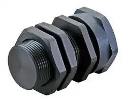


Y92E-J12S18
Mounting Sleeve, E2E NEXT M12 Shielded Sensors
- Manufacturer: OMRON INDUSTRIAL AUTOMATION
- Product type:
- SVHC: To Be Advised
| Delivery and price | |
|---|---|
| Units per pack | 1 |
| Price | 14.58 € |
| Current stock | 10+ |
| Lead time | 30 days |
**Proximity Sensor E2E/E2EQ NEXT Series DC 2-wire** ## **Long-distance Detection Prevents Unexpected Facility Stoppages** - Exceptional sensing distance*[1] . Nearly double the sensing distance of previous models. - With high-brightness LED, indicator is visible 360° around. - Only 10 seconds*[2] to replace a Proximity Sensor with Quick fix (Mounting Sleeve). - Cables with enhanced oil resistance have 2-year oil *[3] - resistance . - IP69K compliant for water resistance and wash resistance.[*4] - UL certification (UL60947-5-2) and CSA certification (CSA C22.2 UL60947-5-2-14) - *1. Based on July 2017 OMRON investigation. - *2. Time required to adjust the distance when installing a Sensor. Based on OMRON investigation. - *3. Refer to page 6 and 8 for details. However, E2EQ series is excluded. For the most recent information on models that have been certified for safety standards, refer to your OMRON website. *4. E2EQ series is excluded. Be sure to read _Safety Precautions_ on page 15. ~~Ao~~ ## **E2E/E2EQ NEXT Series Model Number Legend** ## **DC 2-wire** |**No.**|**Classification**<br>ee|**Code**<br>ee|**Meaning**| |---|---|---|---| |(1)|Case<br>~~PE~~|Blank<br>~~PE~~|Without spatter-resistant coating| |||Q<br>~~PE~~|With spatter-resistant coating| |(2)|Sensing distance<br>~~PE~~<br>po|Number<br>~~PE~~<br>po|Sensing distance (Unit: mm) (R: Indication of decimal point)| |(3)|Shielding<br>po<br>PE|Blank<br>po<br>PE|Shielded Models| |||M<br>PE|Unshielded Models| |(4)|Operation mode<br>PE<br>PP|1<br>PE<br>PP|Normally open (NO)| |||2<br>PP|Normally closed (NC)| |(5)|Body size<br>PP<br>PP|Blank<br>PP<br>PP|Standard| |||L<br>PP|Long Body| |(6)|Size<br>(Omitted for the Single<br>distance type.)<br>PP<br>=|8<br>PP<br>=|M8<br>| |||12<br>=|M12<br>| |||18<br>=—|M18<br>—| |||30<br>=—|M30<br>—| |(7)|Connecting method<br>=<br>=|Blank<br>=—<br>=|Pre-wired Models<br>—| |||M1TGJ<br>=|M12 Pre-wired Smartclick Connector Models pigtail| |||M1TGJR<br>=<br>po|M12 Pre-wired Smartclick Connector Models (Robot (bending-resistant) PVC cable) robot pigtail| |(8)|Polarity<br>=<br>PP|Blank<br>=<br>po<br>PP|Polarity| |||T<br>PP|No polarity| |(9)|Cable specifications *<br>PP<br>PE|Blank<br>PP<br>PE|Standard PVC cable| |||R<br>PE|Robot (bending-resistant) PVC cable| |(10)|New model<br>PE<br>PP|Blank<br>PE<br>PP|Other than Single distance model (Pre-wired Models)| |||N<br>PP|Single distance model (Applicable only to Pre-wired Models)| |(11)|Cable length<br>PP<br>es|Number M<br>PP<br>es|Cable length| - (9) is only shown in the model number of Pre-wired Models. - **Note: 1.** The purpose of this model number legend is to provide understanding of the meaning of specifications from the model number. Models are not available for all combinations of code numbers. **2.** Size description of the number 7 is not included in the Single-distance type. **1** **E2E/E2EQ NEXT Series Ordering Information** ## **Sensors** ## **E2E NEXT Series (Triple distance model) DC 2-wire [Refer to** _**Dimensions**_ **on page 18.] Shielded Models *1** |**Size**<br>**(Sensing distance)**|**Connection method**|**Polarity**|**Model**|**Model**| |---|---|---|---|---| ||||**Operation mode: NO**|**Operation mode: NC**| |M8<br>(3 mm)|Pre-wired (2 m)*2*3|Yes|**E2E-X3D18 2M**|**E2E-X3D28 2M**| |||No|**E2E-X3D18-T 2M**|**E2E-X3D28-T 2M**| ||M12 Pre-wired<br>Smartclick Connector (0.3 m)*4|Yes|**E2E-X3D18-M1TGJ 0.3M**|**E2E-X3D28-M1TGJ 0.3M**| |||No|**E2E-X3D18-M1TGJ-T 0.3M**|**E2E-X3D28-M1TGJ-T 0.3M**| |M12<br>(7 mm)|Pre-wired (2 m)*2*3|Yes|**E2E-X7D112 2M**|**E2E-X7D212 2M**| |||No|**E2E-X7D112-T 2M**|**E2E-X7D212-T 2M**| ||M12 Pre-wired<br>Smartclick Connector (0.3 m)*4|Yes|**E2E-X7D112-M1TGJ 0.3M**|**E2E-X7D212-M1TGJ 0.3M**| |||No|**E2E-X7D112-M1TGJ-T 0.3M**|**E2E-X7D212-M1TGJ-T 0.3M**| |M18<br>(11 mm)|Pre-wired (2 m)*2*3|Yes|**E2E-X11D118 2M**|**E2E-X11D218 2M**| |||No|**E2E-X11D118-T 2M**|**E2E-X11D218-T 2M**| ||M12 Pre-wired<br>Smartclick Connector (0.3 m)*4|Yes|**E2E-X11D118-M1TGJ 0.3M**|**E2E-X11D218-M1TGJ 0.3M**| |||No|**E2E-X11D118-M1TGJ-T 0.3M**|**E2E-X11D218-M1TGJ-T 0.3M**| |M30<br>(20 mm)|Pre-wired (2 m)*2*3|Yes|**E2E-X20D130 2M**|**E2E-X20D230 2M**| |||No|**E2E-X20D130-T 2M**|**E2E-X20D230-T 2M**| ||M12 Pre-wired<br>Smartclick Connector (0.3 m)*4|Yes|**E2E-X20D130-M1TGJ 0.3M**|**E2E-X20D230-M1TGJ 0.3M**| |||No|**E2E-X20D130-M1TGJ-T 0.3M**|**E2E-X20D230-M1TGJ-T 0.3M**| ## **Unshielded Models** |**Size**<br>**(Sensing distance)**|**Connection method**|**Polarity**|**Model**|**Model**| |---|---|---|---|---| ||||**Operation mode: NO**|**Operation mode: NC**| |M8<br>(6 mm)|Pre-wired (2 m)*2*3|Yes|**E2E-X6MD18 2M**|**E2E-X6MD28 2M**| |||No|**E2E-X6MD18-T 2M**|**E2E-X6MD28-T 2M**| ||M12 Pre-wired<br>Smartclick Connector (0.3 m)*4|Yes|**E2E-X6MD18-M1TGJ 0.3M**|**E2E-X6MD28-M1TGJ 0.3M**| |||No|**E2E-X6MD18-M1TGJ-T 0.3M**|**E2E-X6MD28-M1TGJ-T 0.3M**| |M12<br>(10 mm)|Pre-wired (2 m)*2*3|Yes|**E2E-X10MD112 2M**|**E2E-X10MD212 2M**| |||No|**E2E-X10MD112-T 2M**|**E2E-X10MD212-T 2M**| ||M12 Pre-wired<br>Smartclick Connector (0.3 m)*4|Yes|**E2E-X10MD112-M1TGJ 0.3M**|**E2E-X10MD212-M1TGJ 0.3M**| |||No|**E2E-X10MD112-M1TGJ-T 0.3M**|**E2E-X10MD212-M1TGJ-T 0.3M**| |M18<br>(20 mm)|Pre-wired (2 m)*2*3|Yes|**E2E-X20MD1L18 2M**|**E2E-X20MD2L18 2M**| |||No|**E2E-X20MD1L18-T 2M**|**E2E-X20MD2L18-T 2M**| ||M12 Pre-wired<br>Smartclick Connector (0.3 m)*4|Yes|**E2E-X20MD1L18-M1TGJ 0.3M**|**E2E-X20MD2L18-M1TGJ 0.3M**| |||No|**E2E-X20MD1L18-M1TGJ-T 0.3M**|**E2E-X20MD2L18-M1TGJ-T 0.3M**| |M30<br>(40 mm)|Pre-wired (2 m)*2*3|Yes|**E2E-X40MD1L30 2M**|**E2E-X40MD2L30 2M**| |||No|**E2E-X40MD1L30-T 2M**|**E2E-X40MD2L30-T 2M**| ||M12 Pre-wired<br>Smartclick Connector (0.3 m)*4|Yes|**E2E-X40MD1L30-M1TGJ 0.3M**|**E2E-X40MD2L30-M1TGJ 0.3M**| |||No|**E2E-X40MD1L30-M1TGJ-T 0.3M**|**E2E-X40MD2L30-M1TGJ-T 0.3M**| - *1. When embedding the Proximity Sensor in metal, refer to _Influence of Surrounding Metal_ on page 16. - *2. Models with 5-m cable length are also available with "5M" suffix. (Example: E2E-X3D18 5M) - *3. Models with 2-m and 5-m robot (bending-resistant) cables are also available with "-R" in the model number. (Example: E2E-X3D18-R 2M/E2EX3D18-R 5M) - *4. Models with M12 Pre-wired Smartclick Connectors and robot (bending-resistant) cables are also available with "R" in the model number. (Example: E2E-X3D18-M1TGJR 0.3M/E2E-X3D18-M1TGJR-T 0.3M) **2** **E2E/E2EQ NEXT Series** ## **Sensors** ## **E2EQ NEXT Series (Spatter-resistant Triple distance model) DC 2-wire [Refer to** _**Dimensions**_ **on page 21.] Shielded Models *1** |**Size**<br>**(Sensing distance)**|**Connection method**|**Polarity**|**Model**|**Model**| |---|---|---|---|---| ||||**Operation mode: NO**|**Operation mode: NC**| |M8<br>(3 mm)|Pre-wired (2 m)*2|Yes|**E2EQ-X3D18 2M**|**E2EQ-X3D28 2M**| |||No|**E2EQ-X3D18-T 2M**|**E2EQ-X3D28-T 2M**| ||M12 Pre-wired<br>Smartclick Connector (0.3 m)|Yes|**E2EQ-X3D18-M1TGJ 0.3M**|**E2EQ-X3D28-M1TGJ 0.3M**| |||No|**E2EQ-X3D18-M1TGJ-T 0.3M**|**E2EQ-X3D28-M1TGJ-T 0.3M**| |M12<br>(7 mm)|Pre-wired (2 m)*2|Yes|**E2EQ-X7D112 2M**|**E2EQ-X7D212 2M**| |||No|**E2EQ-X7D112-T 2M**|**E2EQ-X7D212-T 2M**| ||M12 Pre-wired<br>Smartclick Connector (0.3 m)|Yes|**E2EQ-X7D112-M1TGJ 0.3M**|**E2EQ-X7D212-M1TGJ 0.3M**| |||No|**E2EQ-X7D112-M1TGJ-T 0.3M**|**E2EQ-X7D212-M1TGJ-T 0.3M**| |M18<br>(11 mm)|Pre-wired (2 m)*2|Yes|**E2EQ-X11D118 2M**|**E2EQ-X11D218 2M**| |||No|**E2EQ-X11D118-T 2M**|**E2EQ-X11D218-T 2M**| ||M12 Pre-wired<br>Smartclick Connector (0.3 m)|Yes|**E2EQ-X11D118-M1TGJ 0.3M**|**E2EQ-X11D218-M1TGJ 0.3M**| |||No|**E2EQ-X11D118-M1TGJ-T 0.3M**|**E2EQ-X11D218-M1TGJ-T 0.3M**| |M30<br>(20 mm)|Pre-wired (2 m)*2|Yes|**E2EQ-X20D130 2M**|**E2EQ-X20D230 2M**| |||No|**E2EQ-X20D130-T 2M**|**E2EQ-X20D230-T 2M**| ||M12 Pre-wired<br>Smartclick Connector (0.3 m)|Yes|**E2EQ-X20D130-M1TGJ 0.3M**|**E2EQ-X20D230-M1TGJ 0.3M**| |||No|**E2EQ-X20D130-M1TGJ-T 0.3M**|**E2EQ-X20D230-M1TGJ-T 0.3M**| - *1. When embedding the Proximity Sensor in metal, refer to _Influence of Surrounding Metal_ on page 16. - *2. Models with 5-m cable length are also available with "5M" suffix. (Example: E2EQ-X3D18 5M) ## **E2E NEXT Series (Single distance model)** **DC 2-wire [Refer to** _**Dimensions**_ **on page 22.] Shielded Models** |**Size**<br>**(Sensing distance)**|**Connection method**|**Polarity**|**Model**|**Model**| |---|---|---|---|---| ||||**Operation mode: NO**|**Operation mode: NC**| |M8<br>(1.5 mm)|Pre-wired (2 m)*2*3|Yes|**E2E-X1R5D1-N 2M**|**E2E-X1R5D2-N 2M**| |||No|**E2E-X1R5D1-T-N 2M**|**E2E-X1R5D2-T-N 2M**| ||M12 Pre-wired<br>Smartclick Connector (0.3 m)*4|Yes|**E2E-X1R5D1-M1TGJ 0.3M**|**E2E-X1R5D2-M1TGJ 0.3M**| |||No|**E2E-X1R5D1-M1TGJ-T 0.3M**|**E2E-X1R5D2-M1TGJ-T 0.3M**| |M12<br>(2.5 mm)|Pre-wired (2 m)*2*3|Yes|**E2E-X2R5D1-N 2M**|**E2E-X2R5D2-N 2M**| |||No|**E2E-X2R5D1-T-N 2M**|**E2E-X2R5D2-T-N 2M**| ||M12 Pre-wired<br>Smartclick Connector (0.3 m)*4|Yes|**E2E-X2R5D1-M1TGJ 0.3M**|**E2E-X2R5D2-M1TGJ 0.3M**| |||No|**E2E-X2R5D1-M1TGJ-T 0.3M**|**E2E-X2R5D2-M1TGJ-T 0.3M**| |M18<br>(5 mm)|Pre-wired (2 m)*2*3|Yes|**E2E-X5D1-N 2M**|**E2E-X5D2-N 2M**| |||No|**E2E-X5D1-T-N 2M**|**E2E-X5D2-T-N 2M**| ||M12 Pre-wired<br>Smartclick Connector (0.3 m)*4|Yes|**E2E-X5D1-M1TGJ 0.3M**|**E2E-X5D2-M1TGJ 0.3M**| |||No|**E2E-X5D1-M1TGJ-T 0.3M**|**E2E-X5D2-M1TGJ-T 0.3M**| - *1. Models with 5-m cable length are also available with "5M" suffix. (Example: E2E-X1R5D1-N 5M) - *2. Models with 2-m and 5-m robot (bending-resistant) cables are also available with "-R" in the model number. (Example: E2E-X1R5D1-R-N 2M/ E2E-X1R5D1-R-N 5M) - *3. Models with M12 Smartclick connector model robot (bending-resistant) cables are also available with "R" in the model number. (Example: E2EX1R5D1-M1TGJR 0.3M/E2E-X1R5D1-M1TGJR-T 0.3M) **3** **E2E/E2EQ NEXT Series** ## **Accessories (Sold Separately)** ## **Sensor I/O Connectors** **(Models for Pre-wired Connectors) A Sensor I/O Connector is not provided with the Sensor. It must be ordered separately as required. Round Oil-resistant Connectors XS5 NEXT series** |**Appearance**|**Cable**<br>**Specification**|**Type**|**Cable**<br>**diameter**<br>**(mm)**|**Cable Connection**<br>**Direction**|**Cable**<br>**length**<br>**(m)**|**Sensor I/O Connector**<br>**model number**|**Applicable Proximity**<br>**Sensor model number**| |---|---|---|---|---|---|---|---| |M12<br>Smartclick<br>Connector<br>Straight type<br>P<br>«|Oil-resistant<br>PVC cable|Sockets on One<br>Cable End|6 dia.|Straight|1<br>rs|**XS5F-D421-C80-X**<br>rs|E2E-X□D□-M1TGJ(R)(-T)<br>E2EQ-X□D□-M1TGJ(-T)<br>ee| ||||||2<br>rs<br>ee|**XS5F-D421-D80-X**<br>rs<br>ee|| ||||||3<br>ee<br>ee|**XS5F-D421-E80-X**<br>ee<br>ee|| ||||||5<br>ee<br>es|**XS5F-D421-G80-X**<br>ee<br>es|| ||||||10<br>es<br>ee|**XS5F-D421-J80-X**<br>es<br>ee|| ||Oil-resistant<br>PVC robot cable|Sockets on One<br>Cable End|6 dia.|Straight|1<br>ee<br>ee|**XS5F-D421-C80-XR**<br>ee<br>ee|| ||||||2<br>ee<br>ee|**XS5F-D421-D80-XR**<br>ee<br>ee|| ||||||3<br>ee<br>ee|**XS5F-D421-E80-XR**<br>ee<br>ee|| ||||||5<br>ee<br>ee|**XS5F-D421-G80-XR**<br>ee<br>ee|| ||||||10<br>ee<br>es|**XS5F-D421-J80-XR**<br>ee<br>es|| ||Oil-resistant<br>PVC cable|Socket and Plug<br>on Cable Ends|6 dia.|Straight (Socket)/<br>Straight (Plug)|1<br>es<br>ee|**XS5W-D421-C81-X**<br>es<br>ee|| ||||||2<br>ee<br>ee|**XS5W-D421-D81-X**<br>ee<br>ee|| ||||||3<br>ee<br>ee<br>ee|**XS5W-D421-E81-X**<br>ee<br>ee<br>ee|| ||||||5<br>ee<br>ee|**XS5W-D421-G81-X**<br>ee<br>ee|| ||||||10<br>ee<br>ee|**XS5W-D421-J81-X**<br>ee<br>ee|| ||Oil-resistant<br>PVC robot cable|Socket and Plug<br>on Cable Ends|6 dia.|Straight (Socket)/<br>Straight (Plug)|1<br>ee<br>es|**XS5W-D421-C81-XR**<br>ee<br>es|| ||||||2<br>es<br>ee|**XS5W-D421-D81-XR**<br>es<br>ee|| ||||||3<br>ee<br>ee|**XS5W-D421-E81-XR**<br>ee<br>ee|| ||||||5<br>ee<br>ee<br>es|**XS5W-D421-G81-XR**<br>ee<br>ee<br>ee|| ||||||10<br>ee<br>es|**XS5W-D421-J81-XR**<br>ee<br>ee|| **Note:** For details of the connector, refer to _XS5 NEXT Series_ on page 87. ## **Round Water-resistant Connectors XS5 series** |**Appearance**|**Cable**<br>**Specification**|**Type**|**Cable**<br>**diameter**<br>**(mm)**|**Cable Connection**<br>**Direction**|**Cable**<br>**length**<br>**(m)**|**Sensor I/O Connector**<br>**model number**|**Applicable Proximity**<br>**Sensor model number**| |---|---|---|---|---|---|---|---| |M12<br>Smartclick<br>Connector<br>Straight type<br>Right-angle type<br>_|PVC robot cable|Sockets on One<br>Cable End|6 dia.|Straight|1<br>ee|**XS5F-D421-C80-F**<br>ee|E2E-X□D□-M1TGJ(R)(-T)<br>E2EQ-X□D□-M1TGJ(-T)<br>ee<br>ee| ||||||2<br>ee<br>ee|**XS5F-D421-D80-F**<br>ee<br>ee|| ||||||3<br>ee<br>ee|**XS5F-D421-E80-F**<br>ee<br>ee|| ||||||5<br>ee<br>ee<br>es|**XS5F-D421-G80-F**<br>ee<br>ee<br>ee|| ||||||10<br>ee<br>es|**XS5F-D421-J80-F**<br>ee<br>ee|| |||||Right-angle|1<br>es <br>ee|**XS5F-D422-C80-F**<br> ee<br>ee|| ||||||2<br>ee<br>ee|**XS5F-D422-D80-F**<br>ee<br>ee|| ||||||3<br>ee<br>ee|**XS5F-D422-E80-F**<br>ee<br>ee|| ||||||5<br>ee<br>ee|**XS5F-D422-G80-F**<br>ee<br>ee|| ||||||10<br>ee|**XS5F-D422-J80-F**<br>ee|| |||Socket and Plug<br>on Cable Ends|6 dia.|Straight (Socket)/<br>Straight (Plug)|1|**XS5W-D421-C81-F**|| ||||||2<br>ee|**XS5W-D421-D81-F**<br>ee|| ||||||3<br>ee<br>ee|**XS5W-D421-E81-F**<br>ee<br>ee|| ||||||5<br>ee<br>ee<br>es|**XS5W-D421-G81-F**<br>ee<br>ee<br>ee|| ||||||10<br>ee<br>es|**XS5W-D421-J81-F**<br>ee<br>ee|| |||||Right-angle (Socket)/<br>Right-angle (Plug)<br>ee|2<br>es|**XS5W-D422-D81-F**<br>ee|| ||||||5<br>es <br>ee|**XS5W-D422-G81-F**<br> ee<br>eee|| |||||Straight (Socket)/<br>Right-angle (Plug)<br>ee|2<br>ee|**XS5W-D423-D81-F**<br>eee|| ||||||5<br>ee<br>a|**XS5W-D423-G81-F**<br>eee<br>a|| |||||Right-angle (Socket)/<br>Straight (Plug)<br>ee <br>Lt|2<br> ee <br>a<br>Lt|**XS5W-D424-D81-F**<br> eee<br>a<br>Lt|| ||||||5<br>Lt<br>a|**XS5W-D424-G81-F**<br>Lt<br> ee|| **Note:** For details of the connector, refer to _XS5 Series_ on page 94. **4** **E2E/E2EQ NEXT Series** **Sensor I/O Connectors Oil resistance performance of mating combination** **E2E NEXT Series Applicable connector Model Pre-wired Connector Models XS5 NEXT series XS5 series** E2E-X □ D □ -M1TGJ(R)(-T) 2 years of oil resistance* Water-resistant (IP67) ~~———~~ * Applicable cutting oil type: specified in JIS K 2241:2000 2 years of oil resistance indicates the median value of the product design and the oil-resistance performance criterion result (=Typical value). Products to be shipped will have approximately 2 years of oil resistance, but will very depending on the product. ## **Quick fix (Mounting Sleeves) [Refer to Dimensions on page 23.]** A Mounting Bracket is not provided with the Sensor. It must be ordered separately as required. **Appearance Model Applicable Sensors** Y92E-J8S12 E2E NEXT M8 Shielded Sensors Y92E-J12S18 E2E NEXT M12 Shielded Sensors Y92E-J18S30 E2E NEXT M18 Shielded Sensors ~~oO~~ **Note:** Not applicable for E2EQ NEXT Series (spatter-resistant) models. **5** **E2E/E2EQ NEXT Series** ## **Ratings and Specifications** ## **E2E NEXT Series (Triple distance model)** ## **DC 2-wire** |**Size**|**Size**|**M8**|**M8**|**M12**|**M12**|**M18**|**M18**|**M30**|**M30**| |---|---|---|---|---|---|---|---|---|---| |**Shielded**||**Shielded**|**Unshielded**|**Shielded**|**Unshielded**|**Shielded**|**Unshielded**|**Shielded**|**Unshielded**| |**Item**<br>**Model**||**E2E-X3D□**|**E2E-X6MD□**|**E2E-X7D□**|**E2E-X10MD□**|**E2E-X11D□**|**E2E-X20MD□**|**E2E-X20D□**|**E2E-X40MD□**| |**Sensing distance**||3 mm ±10%|6 mm ±10%|7 mm ±10%|10 mm ±10%|11 mm ±10%|20 mm ±10%|20 mm ±10%|40 mm ±10%| |**Setting distance*1**||0 to 2.4 mm|0 to 4.8 mm|0 to 5.6 mm|0 to 8 mm|0 to 8.8 mm|0 to 16 mm|0 to 16 mm|0 to 32 mm| |**Differential travel**||15% max. of sensing distance|||||||| |**Detectable object**||Ferrous metal (The sensing distance decreases with non-ferrous metal. Refer to_Engineering Data_on page 9.)|||||||| |**Standard sensing object**||Iron,<br>9 × 9 × 1 mm|Iron,<br>18 × 18 × 1 mm|Iron,<br>21 × 21 × 1 mm|Iron,<br>30 × 30 × 1 mm|Iron,<br>33 × 33 × 1 mm|Iron,<br>60 × 60 × 1 mm|Iron,<br>60 × 60 × 1 mm|Iron,<br>120 × 120 × 1 mm| |**Response frequency*2**||350 Hz|250 Hz|350 Hz|200 Hz|250 Hz|200 Hz|200 Hz|50 Hz| |**Power supply voltage**||10 to 30 VDC, (including 10% ripple (p-p))|||||||| |**Leakage**|**current**|0.8 mA max.|||||||| |**Control**<br>**output**|**Load current**|3 to 100 mA|||||||| ||**Residual**<br>**voltage**|Polarity: 3 V max. (Load current: 100 mA, Cable length: 2 m)<br>No polarity: 5 V max. (Load current: 100 mA, Cable length: 2 m)|||||||| |**Indicator**||D1 Models: Operation indicator (orange), Setting indicator (green)<br>D2 Models: Operation indicator (orange)|||||||| |**Operation mode**||D1 Models: NO<br>D2 Models: NC<br>Refer to the timing charts under_I/O Circuit Diagrams_on page 13 for details.|||||||| |**Protection circuits**||Surge suppressor, Load short-circuit protection|||||||| |**Ambient temperature**<br>**range**||Operating: -25 to 70°C, Storage: -40 to 85°C (with no icing or condensation)|||||||| |**Ambient humidity range**||Operating and Storage: 35% to 95% (with no condensation)|||||||| |**Temperature influence**||±10% max. of sensing distance at 23°C<br>in the temperature range of -25 to 70°C||||±20% max. of<br>sensing<br>distance at<br>23°C in the<br>temperature<br>range of<br>-25 to 70°C|±10% max. of<br>sensing<br>distance at<br>23°C in the<br>temperature<br>range of<br>-25 to 70°C|±20% max. of sensing distance<br>at 23°C in the temperature<br>range of -25 to 70°C|| |**Voltage influence**||±1% max. of sensing distance at rated voltage in the rated voltage ±15% range|||||||| |**Insulation resistance**||50 Mmin. (at 500 VDC) between current-carrying parts and case|||||||| |**Dielectric strength**||1,000 VAC, 50/60 Hz for 1 minute between current-carrying parts and case|||||||| |**Vibration resistance**<br>**(destruction)**||10 to 55 Hz, 1.5-mm double amplitude for 2 hours each in X, Y, and Z directions|||||||| |**Shock resistance**<br>**(destruction)**||500 m/s210 times each in X, Y,<br>and Z directions||1,000 m/s210 times each in X, Y, and Z directions|||||| |**Degree of protection**||Pre-wired Models/Pre-wired Connector Models: IP67 (IEC 60529), IP67G*3 (JIS C 0920 Annex 1) Passed OMRON's Oil-resistant<br>Component Evaluation Standards*4 (Cutting oil type: specified in JIS K 2241:2000, Temperature: 35 °C max.) and ISO 20653 (old<br>standard: DIN 40050 PART9) IP69K|||||||| |**Connecting method**||Pre-wired Models (Standard cable length: 2 m) and Pre-wired Connector Models (Standard cable length: 0.3 m)|||||||| |**Weight**<br>**(packed**<br>**state)**|**Pre-wired**<br>**Models**|Approx. 60 g||Approx. 70 g||Approx. 130 g|Approx. 150 g|Approx. 180 g|Approx. 210 g| ||**Pre-wired**<br>**Connector**<br>**Models**|Approx. 30 g||Approx. 40 g||Approx. 70 g|Approx. 90 g|Approx.110 g|Approx. 140 g| |**Materials**|**Case**|Nickel-plated<br>brass|Stainless steel<br>(SUS303)|Nickel-plated brass|||||| ||**Sensing surface**|Polybutylene terephthalate (PBT)|||||||| ||**Clamping nuts**|Nickel-plated brass|||||||| ||**Toothed washer**|Zinc-plated iron|||||||| ||**Cable**|Vinyl chloride (PVC)|||||||| |**Accessories**||Instruction manual, Clamping nuts, Toothed washer|||||||| - *1. Use the Sensor within the range in which the setting indicator (green LED) is ON (except D2 Models). - *2. The response frequency is an average value. Measurement conditions are as follows: standard sensing object, a distance of twice the standard sensing object, and a set distance of half the sensing distance. - *3. The IP67G is the degree of protection which is defined according to the JIS (Japanese Industrial Standards). The IP67 indicates the same level of protection as defined by the IEC, and the G indicates that a device has resistance to oil. - *4. The Oil-resistant Component Evaluation Standards are OMRON's own durability evaluation standards. - 2-year oil resistance indicates the median value of the product design and the oil-resistance performance criterion result (=Typical value). The Pre-wired Connector Model verifies 2 years of oil resistance when mating with Round Oil-resistant Connectors XS5 NEXT series correctly. The degree of protection is not satisfied with the part where cable wires are uncovered for the Pre-wired Models. **6** **E2E/E2EQ NEXT Series** **E2EQ NEXT Series (Spatter-resistant Triple distance model) DC 2-wire** |**Size**|**Size**|**M8**|**M12**|**M18**|**M30**| |---|---|---|---|---|---| |**Shielded**||**Shielded**|||| |**Item**<br>**Model**||**E2EQ-X3D□**|**E2EQ-X7D□**|**E2EQ-X11D□**|**E2EQ-X20D□**| |**Sensing distance**||3 mm ±10%|7 mm ±10%|11 mm ±10%|20 mm ±10%| |**Setting distance*1**||0 to 2.4 mm|0 to 5.6 mm|0 to 8.8 mm|0 to 16 mm| |**Differential travel**||15% max. of sensing distance|||| |**Detectable object**||Ferrous metal (The sensing distance decreases with non-ferrous metal. Refer to_Engineering Data_on page 9.)|||| |**Standard sensing object**||Iron, 9 × 9 × 1 mm|Iron, 21 × 21 × 1 mm|Iron, 33 × 33 × 1 mm|Iron, 60 × 60 × 1 mm| |**Response frequency*2**||250 Hz|250 Hz|250 Hz|200 Hz| |**Power supply voltage**||10 to 30 VDC, (including 10% ripple (p-p))|||| |**Leakage current**||0.8 mA max.|||| |**Control output**|**Load current**|3 to 100 mA|||| ||**Residual voltage**|Polarity: 3 V max. (Load current: 100 mA, Cable length: 2 m)<br>No polarity: 5 V max. (Load current: 100 mA, Cable length: 2 m)|||| |**Indicator**||D1 Models: Operation indicator (orange), Setting indicator (green)<br>D2 Models: Operation indicator (orange)|||| |**Operation mode**||D1 Models: NO<br>D2 Models: NC<br>Refer to the timing charts under_I/O Circuit Diagrams_on page 13 for details.|||| |**Protection circuits**||Surge suppressor, Load short-circuit protection|||| |**Ambient temperature range**||Operating: -25 to 70°C, Storage: -40 to 85°C (with no icing or condensation)|||| |**Ambient humidity range**||Operating and Storage: 35% to 95% (with no condensation)|||| |**Temperature influence**||±10% max. of sensing distance at 23°C<br>in the temperature range of -25 to 70°C||±20% max. of sensing distance at 23°C<br>in the temperature range of -25 to 70°C|| |**Voltage influence**||±1% max. of sensing distance at rated voltage in the rated voltage ±15% range|||| |**Insulation resistance**||50 Mmin. (at 500 VDC) between current-carrying parts and case|||| |**Dielectric strength**||1,000 VAC, 50/60 Hz for 1 minute between current-carrying parts and case|||| |**Vibration resistance (destruction)**||10 to 55 Hz, 1.5-mm double amplitude for 2 hours each in X, Y, and Z directions|||| |**Shock resistance (destruction)**||500 m/s210 times each in<br>X, Y, and Z directions|1,000 m/s210 times each in X, Y, and Z directions||| |**Degree of protection**||Pre-wired Models/Pre-wired Connector Models: IP67 (IEC 60529) and IP67G*3 (JIS C 0920 Annex 1)|||| |**Connecting method**||Pre-wired Models (Standard cable length: 2 m) and Pre-wired Connector Models (Standard cable length: 0.3 m)|||| |**Weight**<br>**(packed state)**|**Pre-wired Models**|Approx. 60 g|Approx. 70 g|Approx. 150 g|Approx. 210 g| ||**Pre-wired Connector**<br>**Models**|Approx. 30 g|Approx. 40 g|Approx. 90 g|Approx. 140 g| |**Materials**|**Case**|Fluororesin coating (Base material: brass)|||| ||**Sensing surface**|Fluororesin|||| ||**Clamping nuts**|Fluororesin coating (Base material: brass)|||| ||**Toothed washer**|Zinc-plated iron|||| ||**Cable**|Vinyl chloride (PVC)|||| |**Accessories**||Instruction manual, Clamping nuts, Toothed washer|||| - *1. Use the Sensor within the range in which the setting indicator (green LED) is ON (except D2 Models). - *2. The response frequency is an average value. Measurement conditions are as follows: standard sensing object, a distance of twice the standard sensing object, and a set distance of half the sensing distance. - *3. The IP67G is the degree of protection which is defined according to the JIS (Japanese Industrial Standards). The IP67 indicates the same level of protection as defined by the IEC, and the G indicates that a device has resistance to oil. **7** **E2E/E2EQ NEXT Series** ## **E2E NEXT Series (Single distance model)** ## **DC 2-wire** |**Size**|**Size**|**M8**|**M12**|**M18**| |---|---|---|---|---| |**Shielded**||**Shielded**||| |**Item**<br>**Model**||**E2E-X1R5D□**|**E2E-X2R5D□**|**E2E-X5D□**| |**Sensing distance**||1.5 mm ±10%|2.5 mm ±10%|5 mm ±10%| |**Setting distance*1**||0 to 1.2 mm|0 to 2 mm|0 to 4 mm| |**Differential travel**||10% max. of sensing distance||| |**Detectable object**||Ferrous metal (The sensing distance decreases with non-ferrous metal. Refer to_Engineering Data_on page 9.)||| |**Standard sensing object**||Iron, 10 × 10 × 1 mm|Iron, 12 × 12 × 1 mm|Iron, 18 × 18 × 1 mm| |**Response frequency*2**||250 Hz|250 Hz|250 Hz| |**Power supply voltage**||10 to 30 VDC, (including 10% ripple (p-p))||| |**Leakage current**||0.8 mA max.||| |**Control output**|**Load current**|3 to 100 mA||| ||**Residual voltage**|Polarity: 3 V max. (Load current: 100 mA, Cable length: 2 m)<br>No polarity: 5 V max. (Load current: 100 mA, Cable length: 2 m)||| |**Indicator**||D1 Models: Operation indicator (orange), Setting indicator (green)<br>D2 Models: Operation indicator (orange)||| |**Operation mode**||D1 Models: NO<br>D2 Models: NC<br>Refer to the timing charts under_I/O Circuit Diagrams_on page 13 for details.||| |**Protection circuits**||Surge suppressor, Load short-circuit protection||| |**Ambient temperature range**||Operating: -25 to 70°C, Storage: -40 to 85°C (with no icing or condensation)||| |**Ambient humidity range**||Operating and Storage: 35% to 95% (with no condensation)||| |**Temperature influence**||±10% max. of sensing distance at 23°C in the temperature range of -25 to 70°C||| |**Voltage influence**||±1% max. of sensing distance at rated voltage in the rated voltage ±15% range||| |**Insulation resistance**||50 Mmin. (at 500 VDC) between current-carrying parts and case||| |**Dielectric strength**||1,000 VAC, 50/60 Hz for 1 minute between current-carrying parts and case||| |**Vibration resistance (destruction)**||10 to 55 Hz, 1.5-mm double amplitude for 2 hours each in X, Y, and Z directions||| |**Shock resistance (destruction)**||500 m/s210 times each in X, Y, and Z<br>directions|1,000 m/s210 times each in X, Y, and Z directions|| |**Degree of protection**||Pre-wired Models/Pre-wired Connector Models: IP67 (IEC 60529), IP67G*3 (JIS C 0920 Annex 1) Passed OMRON's<br>Oil-resistant Component Evaluation Standards*4 (Cutting oil type: specified in JIS K 2241:2000, Temperature: 35°C<br>max.) and ISO 20653 (old standard: DIN 40050 PART9) IP69K||| |**Connecting method**||Pre-wired Models (Standard cable length: 2 m) and Pre-wired Connector Models (Standard cable length: 0.3 m)||| |**Weight**<br>**(packed state)**|**Pre-wired Models**|Approx. 60 g|Approx. 70 g|Approx. 130 g| ||**Pre-wired Connector**<br>**Models**|Approx. 30 g|Approx. 40 g|Approx. 70 g| |**Materials**|**Case**|Stainless steel (SUS303)|Nickel-plated brass|| ||**Sensing surface**|Polybutylene terephthalate (PBT)||| ||**Clamping nuts**|Nickel-plated brass||| ||**Toothed washer**|Zinc-plated iron||| ||**Cable**|Vinyl chloride (PVC)||| |**Accessories**||Instruction manual, Clamping nuts, Toothed washer||| - *1. Use the Sensor within the range in which the setting indicator (green LED) is ON (except D2 Models). - *2. The response frequency is an average value. Measurement conditions are as follows: standard sensing object, a distance of twice the standard. - *3. The IP67G is the degree of protection which is defined according to the JIS (Japanese Industrial Standards). The IP67 indicates the same level of protection as defined by the IEC, and the G indicates that a device has resistance to oil. - *4. The Oil-resistant Component Evaluation Standards are OMRON's own durability evaluation standards. 2-year oil resistance indicates the median value of the product design and the oil-resistance performance criterion result (=Typical value). The Pre-wired Connector Model verifies 2 years of oil resistance when mating with Round Oil-resistant Connectors XS5 NEXT series correctly. The degree of protection is not satisfied with the part where cable wires are uncovered for the Pre-wired Models. **8** **E2E/E2EQ NEXT Series** ## **Engineering Data (Reference Value)** ## **Sensing Area** **Triple distance model, Spatter-resistant Triple distance model Shielded Models Unshielded Models** **Unshielded Models E2E-X □ MD □** **==> picture [379 x 163] intentionally omitted <==** **----- Start of picture text -----**<br> E2E(Q)-X □ D □ E2E-X □ MD □<br>20 40<br>E2E(Q)-X20D @ 30 E2E-X40MD@L30<br>35<br>15 30<br>E2E(Q)-X11D @ 18 25 E2E-X20MD@L18<br>10 E2E(Q)-X7D @ 12 20<br>E2E-X10MD@12<br>15<br>5 E2E(Q)-X3D @ 8 10<br>5<br>E2E-X6MD@8<br>0 0<br>-15 -10 -5 0 5 10 15 -30 -20 -10 0 10 20 30<br>Distance Y (mm) Distance Y (mm)<br>Distance X (mm) Distance X (mm)<br>Y<br>X<br>Y<br>X<br>**----- End of picture text -----**<br> ## **Single distance model Shielded Models E2E-X1R5D □ /-X2R5D □ /-X5D □** **==> picture [173 x 145] intentionally omitted <==** **----- Start of picture text -----**<br> 6<br>E2E-X5D@<br>5<br>4<br>E2E-X2R5D@<br>3<br>2<br>1 E2E-X1R5D@<br>0<br>-10 -5 0 5 10<br>Distance Y (mm)<br>Distance X (mm)<br>Y<br>X<br>**----- End of picture text -----**<br> **9** **E2E/E2EQ NEXT Series** ## **Influence of Sensing Object Size and Materials Triple distance model, Spatter-resistant Triple distance model Shielded Models Unshielded Models** **==> picture [500 x 545] intentionally omitted <==** **----- Start of picture text -----**<br> Triple distance model, Spatter-resistant Triple distance model Single distance model<br>Shielded Models Unshielded Models Shielded Models<br>E2E(Q)-X3D □ 8 E2E-X6MD □ 8 E2E-X1R5D □<br>3.5 7 2.5<br>3.0 @d X t =1 mm 6 @d X t =1 mm Iron @d X t =1 mm<br>Iron 2.0<br>2.5 5<br>Stainless steel Iron<br>2.0 Stainless steel 4 (SUS304) 1.5<br>(SUS304) Stainless steel<br>(SUS304)<br>1.5 Brass 3<br>Aluminum Brass 1.0<br>1.0 Copper 2 Aluminum Brass<br>Copper 0.5<br>0.5 1 Aluminum<br>0.0 0<br>0 5 10 15 20 0 5 10 15 20 25 30 35 0 5 10 15 20 25<br>Side length of sensing object: d (mm) Side length of sensing object: d (mm) Side length of sensing object: d (mm)<br>E2E(Q)-X7D □ 12 E2E-X10MD □ 12 E2E-X2R5D □<br>8 12 3.0<br>7 @d X t =1 mm Iron @d X t =1 mm Iron @d X t =1 mm Iron<br>10 2.5<br>6<br>Stainless steel 8 Stainless steel 2.0 Stainless steel<br>5 (SUS304) (SUS304) (SUS304)<br>4 6 1.5<br>3 Brass Brass Brass<br>Aluminum 4 Aluminum 1.0<br>2 Copper Copper Aluminum<br>2 0.5<br>1<br>0 0<br>0 10 20 30 40 50 0 10 20 30 40 50 60 0 5 10 15 20 25 30<br>Side length of sensing object: d (mm) Side length of sensing object: d (mm) Side length of sensing object: d (mm)<br>E2E(Q)-X11D □ 18 E2E-X20MD □ L18 E2E-X5D □<br>12 25 7<br>Iron<br>@d t =1 mm @d @d t =1 mm<br>10 X X t =1 mm Iron 6 X<br>20<br>Iron<br>Stainless steel 5<br>8 (SUS304)<br>15 Stainless steel<br>Stainless steel 4 (SUS304)<br>6 (SUS304)<br>Brass<br>3<br>10<br>4 Aluminum Brass Brass<br>Copper Aluminum 2<br>5 Copper Aluminum<br>2<br>1<br>0 0 0 10 20 30 40 50<br>0 10 20 30 40 50 60 0 20 40 60 80 100<br>Side length of sensing object: d (mm) Side length of sensing object: d (mm) Side length of sensing object: d (mm)<br>E2E(Q)-X20D □ 30 E2E-X40MD □ L30<br>Distance X (mm) Distance X (mm) Distance X (mm)<br>Distance X (mm) Distance X (mm) Distance X (mm)<br>Distance X (mm) Distance X (mm) Distance X (mm)<br>**----- End of picture text -----**<br> **10** **E2E/E2EQ NEXT Series** **==> picture [320 x 150] intentionally omitted <==** **----- Start of picture text -----**<br> 25 45<br>@d @d t =1 mm Iron<br>X t =1 mm 40 X<br>Iron<br>20 35<br>30 Stainless steel<br>(SUS304)<br>15 Stainless steel<br>(SUS304) 25<br>20 Brass<br>10<br>Brass<br>15<br>Aluminum<br>Aluminum<br>10 Copper<br>5 Copper<br>5<br>0 0<br>0 20 40 60 80 100 0 50 100 150 200<br>Side length of sensing object: d (mm) Side length of sensing object: d (mm)<br>Distance X (mm) Distance X (mm)<br>**----- End of picture text -----**<br> **11** ## **E2E/E2EQ NEXT Series** ## **Leakage Current** ## **Triple distance model, Spatter-resistant Triple distance model, Single distance model** ## **E2E-X □ (M)D □ (-T)/E2EQ-X □ D □ (-T)** **==> picture [152 x 148] intentionally omitted <==** **----- Start of picture text -----**<br> 1.0<br>0.8<br>0.6<br>0.4<br>0.2<br>0 5 10 15 20 25 30<br>Power supply voltage (V)<br>Leakage curent (mA)<br>**----- End of picture text -----**<br> ## **Residual Output Voltage** **Triple distance model, Spatter-resistant Triple distance model, Single distance model E2E-X □ (M)D □ (-T)/E2EQ-X □ D □ (-T)** **==> picture [148 x 147] intentionally omitted <==** **----- Start of picture text -----**<br> 5<br>4 E2E-X@(M)D@-T/<br>E2EQ-X@D@-T<br>3<br>E2E-X@(M)D@/<br>E2EQ-X@D@<br>2<br>1<br>0<br>1 10 100<br>Load current (mA)<br>Residual output voltage (V)<br>**----- End of picture text -----**<br> **12** **E2E/E2EQ NEXT Series** ## **I/O Circuit Diagrams** ## **DC 2-Wire Models** |**Operation**<br>**mode**|**Model**|**Timing Chart**|**Timing Chart**|**Timing Chart**|**Timing Chart**|**Timing Chart**||||**Output circuit**|**Output circuit**|**Output circuit**|**Output circuit**|**Output circuit**| |---|---|---|---|---|---|---|---|---|---|---|---|---|---|---| |NO|E2E(Q)-X□D1□|(%)<br>8<br>100<br>Sensing<br>object<br>Rated<br>sensing<br>distance<br>Non-<br>sensing<br>area<br>Unstable<br>sensing<br>area||||0<br>0<br>Stable<br>sensing area<br>Set position<br>Proximity<br>Sensor<br>ON<br>OFF<br>ON<br>OFF<br>ON<br>OFF<br>Setting<br>indicator<br>(green)<br>Operation<br>indicator<br>(orange)<br>Control<br>output|Prox<br>se<br>m<br>cir<br>Note: T|||||||0 V<br>er the +V or 0 V side.<br>Load<br>10 to 30 VDC<br>Connector Pin<br>Arrangement<br>Note: Pins 2 and 3<br>are not used.<br>Brown<br>Blue| |||||||||||imity<br>nsor<br>ain<br>cuit|||1<br>4<br>|| |||||||||||||||| |||||||||||||||| |||||||||||he load can be connected to eith||||| |||||||||||||||| ||||||8<br>0|||||||||| ||E2E(Q)-X□D1□-T||||||Note1.<br>Prox<br>sen<br>m<br>cir<br>2|||||||| |||||||||Prox<br>sen<br>m<br>cir||4<br>3<br>imity<br>sor<br>ain<br>cuit||||| |||||||||||||||| |||||||||||||||| |||||||||||||||| |||||||||||||||| |||||||||||||||| |NC|E2E(Q)-X□D2□|<br>|Non-sensing<br>area|||0<br>Sensing area<br>Proximity<br>Sensor<br>Operation<br>indicator<br>(orange)<br>Control<br>output<br>ON<br>OFF<br>ON<br>OFF|Pro<br>se<br>m<br>c<br>Note: T|||||||0 V<br><br><br>her the +V or 0 V side.<br>Load<br>10 to 30 VDC<br>Connector Pin<br>Arrangement<br>Note: Pins 3 and 4<br>are not used.<br>Brown<br>Blue| |||||||||Pro<br>se<br>m<br>c||||||| |||||||||||ximity<br>nsor<br>ain<br>ircuit||||| ||||||||||Pro<br>se<br>m<br>c|ximity<br>nsor<br>ain<br>ircuit||||| |||||||||||||||| ||||Sensing<br>object|||||||||||| |||||||||||2||||| |||||||||||he load can be connected to eit||||| ||||(%)<br>1<br>Rated<br>sensing<br>distance||00|||||||||| ||E2E(Q)-X□D2□-T||||||Note1<br>Pro<br>se<br>m<br>ci<br>2|||||||| |||||||||Pro<br>se<br>m<br>ci||1<br>2<br>ximity<br>nsor<br>ain<br>rcuit||||| |||||||||||||||| |||||||||||||||| |||||||||||||||| |||||||||||||||| **13** **E2E/E2EQ NEXT Series** ## **Connections to Sensor I/O Connectors** ||**Proximity Sensor**|**Proximity Sensor**|**Proximity Sensor**|**Sensor I/O Connector**<br>**model number**|||**Connections**|**Connections**|**Connections**|**Connections**| |---|---|---|---|---|---|---|---|---|---|---| |**Type**|**Polarity**|**Operation**<br>**mode**|**Model**|||||||| |DC 2-wire<br>(Smartclick<br>Connector)|Yes|NO|E2E-X□D1□-M1TGJ<br>E2EQ-X□D1□-M1TGJ|XS5F-D421-□80-X□<br>XS5F-D42□-□80-F<br>XS5W-D421-□81-X□<br>XS5W-D42□-□81-F<br>**Note:** For details of the<br>connector, refer to<br>_XS5 NEXT Series_on<br>page 87.<br>_XS5 Series_on<br>page 94.|XS<br>4<br>3<br>2<br>1<br>4<br>3<br>2<br>1<br>E2E/E2EQ NEXT Series<br>Main<br>circuit||5<br><br><br><br><br>Blue (not connected)<br>Black(−)<br>Brown(+)<br>White (not connected)<br>*|||| |||||||4<br>3<br>2<br>1||||| |||||||||||| |||||||||||| ||No|NC|E2E-X□D2□-M1TGJ<br>E2EQ-X□D2□-M1TGJ||4<br>3<br>2<br>1<br>4<br>3<br>2<br>1<br>Main<br>circuit<br>X<br>E2E/E2EQ NEXT Series||Blue (not connected)<br>Black (not connected)<br>Brown(+)<br>White(−)<br>S5<br>*|||| |||||||4<br>3<br>2<br>1||||| |||||||||||| |||||||||||| ||Yes|NO|E2E-X□D1□-M1TGJ-T<br>E2EQ-X□D1□-M1TGJ-T||4<br>3<br>2<br>1<br>4<br>3<br>2<br>1<br>Main<br>circuit<br>X<br>E2E/E2EQ NEXT Series||Blue (+) (−)<br>Black (−) (+)<br>S5F<br>Brown (not connected)<br>White (not connected)<br>*|||| |||||||4<br>3<br>2<br>1||||| |||||||||||| ||No|NC|E2E-X□D2□-M1TGJ-T<br>E2EQ-X□D2□-M1TGJ-T||4<br>3<br>2<br>1<br>4<br>3<br>2<br>1<br>Main<br>circuit<br>X<br>E2E/E2EQ NEXT Series||White (−)(+)<br>Blue (not connected)<br>Brown (+)(−)<br>Black (not connected)<br>S5F<br>*|||| |||||||4<br>3<br>2<br>1||||| |||||||||||| |||||||||||| **Note:** Different from Proximity Sensor wire colors. * If the XS5W Series Connector which has a socket and plug on the cable ends is connected to the Sensor, this part will be a plug. **14** **E2E/E2EQ NEXT Series** ## **Safety Precautions** ## **Be sure to read the precautions for all models in the website at: http://www.ia.omron.com/.** ## **Warning Indications** **Warning level** Indicates a potentially hazardous situation which, if not avoided, will result in minor or **WARNING** moderate injury, or may result in serious injury or death. Additionally there may be significant property damage. **Precautions for** Supplementary comments on what to do or **Safe Use** avoid doing, to use the product safely. Supplementary comments on what to do or **Precautions for** avoid doing, to prevent failure to operate, **Correct Use** malfunction or undesirable effect on product performance. ## **Precautions for Safe Use** The following precautions must be observed to ensure safe operation. **1.** Do not use the product in an environment where flammable or explosive gas is present. **2.** Do not attempt to disassemble, repair, or modify the product. **3.** Do not use a voltage that exceeds the rated operating voltage range. Applying a voltage that is higher than the operating voltage range may result in damage or burnout. **4.** Be sure that the power supply polarity and other wiring is correct. Incorrect wiring may cause explosion or burnout. **5.** If the power supply is connected directly without a load, the internal elements may explode or burn. Be sure to insert a load when connecting the power supply. **6.** Dispose of this product as industrial waste. ## **Meaning of Product Safety Symbols** **General prohibition** Indicates the instructions of unspecified prohibited action. **Caution, explosion** Indicates the possibility of explosion under specific conditions. ## **Precautions for Correct Use** Do not use this product under ambient conditions that exceed the ratings. ## **Operating Environment** **1.** Do not install the product in the following locations. Doing so may result in product failure or malfunction. - (1) Outdoor locations directly subject to sunlight, rain, snow, water droplets, or oil. - (2) Locations subject to atmospheres with chemical vapors, in particular solvents and acids. ## **WARNING** **This product is not designed or rated for ensuring safety of persons either directly or indirectly. Do not use it for such purposes.** **Risk of explosion. Do not connect sensor to AC power supply.** - (3) Locations subject to corrosive gases. **2.** The Sensor may malfunction if used near ultrasonic cleaning equipment, high-frequency equipment, transceivers, cellular phones, inverters, or other devices that generate a high-frequency electric field. Please refer to the Precautions for Correct Use on the OMRON website (www.ia.omron.com) for typical measures. **3.** Laying the Proximity Sensor wiring in the same conduit or duct as high-voltage wires or power lines may result in incorrect operation and damage due to induction. Wire the Sensor using a separate conduit or independent conduit. **4.** Never use thinner or other solvents. Otherwise, the Sensor surface may be dissolved. **5.** The following conditions shall be observed if you use the product under an environment using cutting oil that may affect product’s life and/or performance. - Usage under the cutting oil condition designated by the specification - Usage under the cutting oil dilution ratio recommended by its manufacturer - Usage in oil or water is prohibited Impact on the product life may differ depending on the oil you use. Before using the cutting oil, make sure that it should not cause deterioration or degradation of sealing components. **15** ## **E2E/E2EQ NEXT Series** ## **Design** ## **Influence of Surrounding Metal** When mounting the Proximity Sensor using a nut, only use the provided nut. And ensure that the minimum distances given in the following table are maintained. **==> picture [374 x 94] intentionally omitted <==** **----- Start of picture text -----**<br> L L<br>d dia. n<br>m<br>D<br>m<br>*3<br>(Unit: mm)<br>**----- End of picture text -----**<br> |**Type**|**Type**|**Item**|**M8**|**M12**|**M18**|**M30**| |---|---|---|---|---|---|---| |**Triple distance model/**<br>**Spatter-resistant Triple**<br>**distance model**<br>**E2E(Q)-X□D□(-T)**<br>***1**|**Shielded**|L|0|0|0|0| |||d|20|20|50|70| |||D|2|4|4|8| |||m|9|18|33|60| |||n|18|20|54|90| |**Triple distance model**<br>**E2E-X□MD□(-T)**<br>***2**|**Unshielded**|L|10|16|31|50*3| |||d|30|50|90|170| |||D|13|20|35|55| |||m|18|30|60|120| |||n|30|50|80|140| |**Single distance model**<br>**E2E-X□R5D□(-T)**<br>**E2E-X5D□(-T)**<br>***2**|**Shielded**|L|0|0|0|---| |||d|8|12|18|| |||D|0|0|0|| |||m|4.5|8|20|| |||n|12|18|27|| **Note:** Nuts that are supplied along with each Sensor (*1, *2) are different. Refer to _Dimensions_ for details on shapes. *3. If you use the M30 Triple distance model of Unshielded Model, the panel thickness (t) is 4 mm or less. When the Proximity Sensor is mounted in metal, ensure that the minimum distances given in the following table are maintained. **==> picture [374 x 86] intentionally omitted <==** **----- Start of picture text -----**<br> I<br>d dia. n<br>m<br>D<br>m I<br>(Unit: mm)<br>**----- End of picture text -----**<br> ||**Type**||**Item**|**M8**|**M12**|**M18**|**M30**| |---|---|---|---|---|---|---|---| ||||I|2|4|4|8| |**Triple distance**|**model/**||d|20|20|50|70| |**Spatter-resistant Triple**<br>**distance model**||**Shielded**|D|2|4|4|8| |**E2E(Q)-X□D□(-T)**|||m|9|18|33|60| ||||n|18|20|54|90| ||||I|13|20|35|55| ||||d|30|50|90|170| |**Triple distance**<br>**E2E-X□MD□(-T)**|**model**|**Unshielded**|D|13|20|35|55| ||||m|18|30|60|120| ||||n|30|50|80|140| ||||I|0|0|0|| ||||d|8|12|18|| |**Single distance model**|||||||| |**E2E-X□R5D□(-T)**||**Shielded**|D|0|0|0|---| |**E2E-X5D□(-T)**|||m|4.5|8|20|| ||||n|12|18|27|| **16** **E2E/E2EQ NEXT Series** ## **Mutual Interference** When the Proximity Sensor is embedded in metal, ensure that the minimum distances given in the following table are maintained. |||||(Unit: mm)<br>**M12**<br>**M18**<br>**M30**<br>40<br>70<br>140<br>30<br>45<br>70<br>120<br>200<br>380<br>100<br>120<br>280<br>30<br>50<br>---<br>20<br>35<br>A<br>B<br>A|(Unit: mm)<br>**M12**<br>**M18**<br>**M30**<br>40<br>70<br>140<br>30<br>45<br>70<br>120<br>200<br>380<br>100<br>120<br>280<br>30<br>50<br>---<br>20<br>35<br>A<br>B<br>A| |---|---|---|---|---|---| |**Type**||**Item**|**M8**|**M12**<br>**M**|**18**<br>**M30**| |**Triple distance model/**<br>**Spatter-resistant Triple**<br>**distance model**<br>**E2E(Q)-X□D□(-T)**|**Shielded**|A|25|40<br>|70<br>140| |||B|20|30<br>|45<br>70| |**Triple distance model**<br>**E2E-X□MD□(-T)**|**Unshielded**|A|80|120<br>2|00<br>380| |||B|60|100<br>1|20<br>280| |**Single distance model**<br>**E2E-X□R5D□(-T)**<br>**E2E-X5D□(-T)**|**Shielded**|A|20|30<br>|50<br>---<br>35| |||B|15|20<br>|| ## **Mounting** ## **Tightening Force** Do not tighten the nut with excessive force. A washer must be used with the nut. **==> picture [52 x 32] intentionally omitted <==** **==> picture [149 x 52] intentionally omitted <==** **----- Start of picture text -----**<br> Shielded Models Unshielded Models<br>Part B Part A Part B Part A<br>**----- End of picture text -----**<br> **Note: 1.** The allowable tightening strength depends on the distance from the edge of the head, as shown in the following table. (A is the distance from the edge of the head. B includes the nut on the head side. If the edge of the nut is in part A, the tightening torque for part A applies instead.) **2.** The following strengths assume washers are being used. ## **Triple distance model** ||**Model**|**Part A**|**Part A**|**Part B**| |---|---|---|---|---| |||**Dimension (mm)**|**Torque**|**Torque**| |M8|Shielded|9|4 N·m|10 N·m| ||Unshielded|3||| |M12|Shielded|16|6 N·m|15 N·m| ||Unshielded|9||| |M18|Shielded|16|15 N·m|60 N·m| ||Unshielded|3||| |M30|Shielded|23|40 N·m|80 N·m| ||Unshielded|8||| ## **Spatter-resistant Triple distance model** |**Model**|**Part A**|**Part A**|**Part B**| |---|---|---|---| ||**Dimension (mm)**|**Torque**|**Torque**| |M8|9|4 N·m|10 N·m| |M12|16|6 N·m|15 N·m| |M18|16|15 N·m|30 N·m| |M30|23|40 N·m|80 N·m| ## **Single distance model** |**Model**|**Part A**|**Part A**|**Part B**| |---|---|---|---| ||**Dimension (mm)**|**Torque**|**Torque**| |M8|9|9 N·m|12 N·m| |M12|---|30 N·m|| |M18||70 N·m|| **17** **E2E/E2EQ NEXT Series** (Unit: mm) ## **Dimensions** Tolerance class IT16 applies to dimensions in this data sheet unless otherwise specified. ## **Sensors** ## **E2E NEXT Series (Triple distance model) DC 2-wire** **==> picture [537 x 562] intentionally omitted <==** **----- Start of picture text -----**<br> Pre-wired Models Pre-wired Models<br>Shielded Unshielded<br>GA IA<br>or ay<br>E2E-X3D □ 8 E2E-X6MD □ 8<br>15 dia. 33.4 37.8 4.4 15 dia. 6 33.4 37.8 4.4<br>26 4-dia. vinyl-insulated round cable with 20<br>13 4 1 0 2 conductors (Conductor cross section: 13 3 8<br>1 4 AWG24, Insulator diameter: 1.05 mm),Standard length: 2 m<br>4-dia. vinyl-insulated round cable with<br>2 conductors (Conductor cross section:<br>Indicators * Indicators * AWG24, Insulator diameter: 1.05 mm),Standard length: 2 m<br>M8 × P1 . Two clamping nuts M8 × P1 Two clamping nuts<br>Toothed washer Toothed washer<br>* D1 Models: Operation indicator (Orange), Setting indicator (Green) * D1 Models: Operation indicator (Orange), Setting indicator (Green)<br> D2 Models: Operation indicator (Orange) D2 Models: Operation indicator (Orange)<br>E2E-X7D □ 12 E2E-X10MD □ 12<br>47.1<br>47.1 3.7<br>21 dia. 43.4 3.7 21 dia. 43.4<br>33<br>17 33 12 4-dia. vinyl-insulated round cable with 17 7 26 4-dia. vinyl-insulated round cable with<br>51.5 4 2 conductors (Conductor cross section: AWG24, Insulator diameter: 1.05 mm), 4 10 2 conductors (Conductor cross section: AWG24, Insulator diameter: 1.05 mm),<br>Standard length: 2 m |tea t Standard length: 2 m<br>Indicators * Indicators *<br>M12 × P1 Two clamping nuts M12 × P1 Two clamping nuts<br>Toothed washer Toothed washer<br>* D1 Models: Operation indicator (Orange), Setting indicator (Green) * D1 Models: Operation indicator (Orange), Setting indicator (Green)<br> D2 Models: Operation indicator (Orange) D2 Models: Operation indicator (Orange)<br>E2E-X11D □ 18 E2E-X20MD □ L18<br>77.3<br>46.8 55.3 8.5 68.8 8.5<br>29 dia.24 1 6 38 12 4 6-dia. vinyl-insulated round cable with 2 conductors (Conductor cross section: AWG20, Insulator diameter: 29 dia.24 13 604 47 12 6-dia. vinyl-insulated round cable with 2 conductors (Conductor cross section: AWG20, Insulator diameter:<br>1.5 mm), Standard length: 2 m 1.5 mm), Standard length: 2 m<br>M18 × P1 Indicators * Indicators *<br>Toothed washer Two clamping nuts M18 × P1 Two clamping nuts<br>* D1 Models: Operation indicator (Orange), Setting indicator (Green) Toothed washer<br> D2 Models: Operation indicator (Orange) * D1 Models: Operation indicator (Orange), Setting indicator (Green)<br> D2 Models: Operation indicator (Orange)<br>E2E-X20D □ 30 E2E-X40MD □ L30<br>60.3<br>52 8.3 74 [82.3] 8.3<br>42 dia.36 1 7 43 12 4 6-dia. vinyl-insulated round cable with 2 conductors (Conductor cross 42 dia.36 15 65 50 5 10 6-dia. vinyl-insulated round cable with 2 conductors (Conductor cross<br>section: AWG20, Insulator diameter: section: AWG20, Insulator diameter:<br>ce =@| 1.5 mm), Standard length: 2 m p= iP 1.5 mm), Standard length: 2 m<br>A CH lb Indicators * © [pe Indicators *<br>Z F M30 × P1.5 Uh Two clamping nuts M30 × P1.5 +-—§ttt Two clamping nuts<br>Toothed washer Toothed washer<br>* D1 Models: Operation indicator (Orange), Setting indicator (Green) * D1 Models: Operation indicator (Orange), Setting indicator (Green)<br> D2 Models: Operation indicator (Orange) D2 Models: Operation indicator (Orange)<br>**----- End of picture text -----**<br> **18** **E2E/E2EQ NEXT Series** ## **Angle R of the Bending Wire** ## **Mounting Hole Dimensions** **==> picture [508 x 658] intentionally omitted <==** **----- Start of picture text -----**<br> Mounting Hole Dimensions Angle R of the Bending Wire Wire pullout position<br>Dimensions F (mm) 10 mm Dimensions R Sc Dimensions Sc<br>M8 8.5 dia. +0.50 M8 (mm) M8 (mm)<br>M12 12.5 dia. +0.50 M12 12 M12 - (0)<br>F M18 18.5 dia. +0.50 R M18 M18<br>M30 30.5 dia. +0.50 M30 18 M30 2.5<br>Pre-wired Connector Models Pre-wired Connector Models<br>Shielded Unshielded<br>“Dd “D<br>E2E-X3D □ 8-M1TGJ E2E-X6MD □ 8-M1TGJ<br>15 dia.13 1 4 2633.4 37.8 4 10 4.4 4-dia. vinyl-insulated round cable with 2 conductors (Conductor cross section: AWG24, Insulator diameter: 1.05 mm), Standard length: 0.3 m 15 dia.13 63 26 37.8 33.420 8 4.4 4-dia. vinyl-insulated round cable with 2 conductors (Conductor cross section: AWG24, Insulator diameter: 1.05 mm), Standard length: 0.3 m<br>j i Esl a Th |= 2<br>Indicators * Indicators *<br>M8 × P1 Two clamping nuts M12 × P1 M8 × P1 Two clamping nuts M12 × P1<br>Toothed washer Toothed washer<br>* D1 Models: Operation indicator (Orange), Setting indicator (Green) * D1 Models: Operation indicator (Orange), Setting indicator (Green)<br> D2 Models: Operation indicator (Orange) D2 Models: Operation indicator (Orange)<br>E2E-X7D □ 12-M1TGJ E2E-X10MD □ 12-M1TGJ<br>47.1<br>21 dia17 . 5.51 33 47.1 43.41 2 4 3.7 4-dia. vinyl-insulated round cable with 2 conductors (Conductor cross section: AWG24, Insulator diameter: 1.05 mm), Standard length: 0.3 m 21 dia.17 7 33443.426 10 3.7 4-dia. vinyl-insulated round cable with 2 conductors(Conductor cross section: AWG24, Insulator diameter: 1.05 mm), Standard length: 0.3 m<br>gt a as et el<br>Poser Indicators * it Sar Indicators *<br>M12 × P1 \ Two clamping nuts M12 × P1 M12 × P1 Two clamping nuts ie M12 × P1<br>Toothed washer Toothed washer<br>* D1 Models: Operation indicator (Orange), Setting indicator (Green) * D1 Models: Operation indicator (Orange), Setting indicator (Green)<br> D2 Models: Operation indicator (Orange) D2 Models: Operation indicator (Orange)<br>E2E-X11D □ 18-M1TGJ E2E-X20MD □ L18-M1TGJ<br>55.3<br>8.5 77.3<br>46.8 68.8 8.5<br>29 dia.24 6 38 12 4 6-dia. vinyl-insulated round cable with 2 conductors (Conductor cross section: AWG20, Insulator diameter: 1.5 mm), 29 dia.24 13 604 47 12 6-dia. vinyl-insulated round cable with 2 conductors (Conductor cross section: AWG20, Insulator diameter:<br>1 Standard length: 0.3 m 1.5 mm), Standard length: 0.3 m<br>Indicators * Indicators *<br>M18 × P1 (He Two clamping nuts nescenge M12 × P1 © M18 × P1 [| Two clamping nuts Speco M12 × P1<br>Toothed washer Toothed washer<br>* D1 Models: Operation indicator (Orange), Setting indicator (Green) * D1 Models: Operation indicator (Orange), Setting indicator (Green)<br> D2 Models: Operation indicator (Orange) D2 Models: Operation indicator (Orange)<br>E2E-X20D □ 30-M1TGJ E2E-X40MD □ L30-M1TGJ<br>4236 dia. 1 7 43 [60.3] 52 12 4 8.36-dia. vinyl-insulated round cable with 2 conductors (Conductor cross section: 4236 dia. 15 65 82.3 7450 5 10 8.3 6-dia. vinyl-insulated round cable with 2 conductors (Conductor cross section: AWG20, Insulator diameter:<br>AWG20, Insulator diameter: 1.5 mm), 1.5 mm), Standard length: 0.3 m<br>Standard length: 0.3 m<br>esl axa<br>i | | hy comm a = _ ry ee Eo la<br>Indicators * M12 × P1 Indicators * M12 × P1<br>M30 × P1.5 Two clamping nuts M30 × P1.5 Two clamping nuts<br>SN Toothed washer \ Toothed washer<br>* D1 Models: Operation indicator (Orange), Setting indicator (Green) * D1 Models: Operation indicator (Orange), Setting indicator (Green)<br> D2 Models: Operation indicator (Orange) D2 Models: Operation indicator (Orange)<br>**----- End of picture text -----**<br> **==> picture [123 x 18] intentionally omitted <==** **----- Start of picture text -----**<br> Pre-wired Connector Models<br>Shielded<br>**----- End of picture text -----**<br> ## **E2E-X20D** □ **30-M1TGJ** **19** **E2E/E2EQ NEXT Series** ## **Mounting Hole Dimensions** ## **Angle R of the Bending Wire Wire pullout position** |**Dimensions**<br>**F (mm)**<br>**M8**<br>8.5 dia.<br>**M12**<br>12.5 dia.<br>**M18**<br>18.5 dia.<br>**M30**<br>30.5 dia.<br>+0.5<br>0<br>+0.5<br>0<br>+0.5<br>0<br>+0.5<br>0<br>10 mm<br>R|**Dimensions**<br>**R**<br>**(mm)**<br>**M8**<br>12<br>**M12**<br>**M18**<br>18<br>**M30**|||Sc||| |---|---|---|---|---|---|---| |**Dimensions**|**Dimensions**<br>||||**Dimensions**<br>|**Sc**<br>**(mm)**| |**M8**||||||| |**M12**|**M8**<br>**M12**||||**M8**<br>**M12**|- (0)| |**M18**||||||| ||**M18**||||**M18**|2.5| |**M30**||||||| ||**M30**||||**M30**|| **20** **E2E/E2EQ NEXT Series** ## **Sensors** ## **E2EQ NEXT Series (Spatter-resistant Triple distance model) DC 2-wire** ## **Pre-wired Models Shielded** ## **E2EQ-X3D** □ **8** **==> picture [496 x 222] intentionally omitted <==** **----- Start of picture text -----**<br> E2EQ-X3D □ 8 E2EQ-X7D □ 12<br>37.8 47.1<br>15 dia. 33.4 4.4 21 dia. 43.4 3.7<br>13 4 26 8 4-dia. vinyl-insulated round cable with 2 conductors (Conductor cross section: 17 5.5 33 1 0 4-dia. vinyl-insulated round cable with 2 conductors (Conductor cross section:<br>1 AWG24, Insulator diameter: 1.05 mm), 1 AWG24, Insulator diameter: 1.05 mm),<br>7 Standard length: 2 m Feo Standard length: 2 m<br>Indicators * Indicators *<br>M8 × P1 Two clamping nuts M12 × P1 Two clamping nuts<br>Toothed washer Toothed washer<br>* D1 Models: Operation indicator (Orange), Setting indicator (Green) * D1 Models: Operation indicator (Orange), Setting indicator (Green)<br> D2 Models: Operation indicator (Orange) D2 Models: Operation indicator (Orange)<br>E2EQ-X11D □ 18 E2EQ-X20D □ 30<br>55.3 60.3<br>29 dia.24 6 3846.8 12 8.5 6-dia. vinyl-insulated round cable with 2 conductors (Conductor cross section: 42 dia.36 1 7 4352 12 8.3 6-dia. vinyl-insulated round cable with 2 conductors (Conductor cross section:<br>1 AWG20, Insulator diameter: 1.5 mm), AWG20, Insulator diameter: 1.5 mm),<br>Standard length: 2 m Standard length: 2 m<br>Ladle tt | Pasa<br>Indicators * Indicators *<br>M18 × P1 Two clamping nuts<br>Toothed washer M30 × P1.5 Toothed washerTwo clamping nuts<br>* D1 Models: Operation indicator (Orange), Setting indicator (Green) * D1 Models: Operation indicator (Orange), Setting indicator (Green)<br> D2 Models: Operation indicator (Orange) D2 Models: Operation indicator (Orange)<br>**----- End of picture text -----**<br> ## **E2EQ-X11D** □ **18** **Pre-wired Connector Models Shielded** **==> picture [501 x 220] intentionally omitted <==** **----- Start of picture text -----**<br> E2EQ-X3D □ 8-M1TGJ E2EQ-X7D □ 12-M1TGJ<br>47.1<br>15 dia. 37.8 33.4 4.4 4-dia. vinyl-insulated round cable with 2 conductors(Conductor cross section: 21 dia.17 43.4 3.7 4-dia. vinyl-insulated round cable with 2 conductors(Conductor cross section:<br>13 1 4 26 8 AWG24, Insulator diameter: 1.05 mm), Standard length: 0.3 m 1 5.5 [33] 1 0 AWG24, Insulator diameter: 1.05 mm), Standard length: 0.3 m<br>al aac.<br>M8 × P1 Two clamping nutsToothed washerIndicators * M12 × P1 M12 × P1 Toothed washerTwo clamping nutsIndicators * M12 × P1<br>* D1 Models: Operation indicator (Orange), Setting indicator (Green) * D1 Models: Operation indicator (Orange), Setting indicator (Green)<br> D2 Models: Operation indicator (Orange) D2 Models: Operation indicator (Orange)<br>E2EQ-X11D □ 18-M1TGJ E2EQ-X20D □ 30-M1TGJ<br>55.3 60.3<br>29 dia.24 6 3846.8 12 8.5 6-dia. vinyl-insulated round cable with 2 conductors(Conductor cross section: AWG20, Insulator diameter: 1.5 mm), 42 dia.36 1 7 4352 12 8.3 6-dia. vinyl-insulated round cable with 2 conductors (Conductor cross section: AWG20, Insulator diameter: 1.5 mm),<br>1 Standard length: 0.3 m Standard length: 0.3 m<br>ied ll Gi<br>la~\ HHHele oe lj=_ (aa lI | ane Lone a]<br>(iam Indicators * © [l[b Indicators e * cne<br>M18 × P1 Two clamping nuts M12 × P1 Two clamping nuts<br>Toothed washer M30 × P1.5 Toothed washer<br>* D1 Models: Operation indicator (Orange), Setting indicator (Green) * D1 Models: Operation indicator (Orange), Setting indicator (Green)<br> D2 Models: Operation indicator (Orange) D2 Models: Operation indicator (Orange)<br>**----- End of picture text -----**<br> ## **E2EQ-X3D** □ **8-M1TGJ** ## **E2EQ-X11D** □ **18-M1TGJ** **==> picture [476 x 79] intentionally omitted <==** **----- Start of picture text -----**<br> Mounting Hole Dimensions Angle R of the Bending Wire Wire pullout position<br>Dimensions F (mm) 10 mm Dimensions R Sc Dimensions Sc<br>M8 8.5 dia. +0.50 M8 (mm) M8 (mm)<br>M12 12.5 dia. +0.50 M12 12 M12 - (0)<br>F M18 18.5 dia. +0.50 R M18 M18<br>== M30 30.5 dia. +0.50 M30 18 M30 2.5<br>**----- End of picture text -----**<br> **21** **E2E/E2EQ NEXT Series** ## **Sensors** ## **E2E NEXT Series (Single distance model) DC 2-wire** ## **Pre-wired Models Shielded** **==> picture [490 x 207] intentionally omitted <==** **----- Start of picture text -----**<br> E2E-X1R5D □ E2E-X2R5D □<br>47<br>37.6 3.7<br> 4.4 43.3<br>15 dia.13 3 25.8 33.2 8 4-dia. vinyl-insulated round cable with 2 conductors (Conductor cross section: AWG24, Insulator diameter: 1.05 mm), 21 dia.17 4 32.9 10 4-dia. vinyl-insulated round cable with 2 conductors (Conductor cross section: AWG24, Insulator diameter: 1.05 mm),<br>Standard length: 2 m Standard length: 2 m<br>M8 × P1 Two clamping nutsIndicators * * D1 Models: Operation indicator (Orange), M12 × P1 Indicators *<br>Toothed washer D2 Models: Operation indicator (Orange)Setting indicator (Green) Toothed washerTwo clamping nuts * D1 Models: Operation indicator (Orange), Setting indicator (Green)<br> D2 Models: Operation indicator (Orange)<br>E2E-X5D □ 54.3<br> 45.8 8.5<br>29 dia. 37 6-dia. vinyl-insulated round cable with<br> 24 4 12 2 conductors (Conductor cross section:<br>AWG20, Insulator diameter: 1.5 mm),<br>Standard length: 2 m<br>Indicators *<br>M18 × P1 * D1 Models: Operation indicator (Orange),<br>| Two clamping nuts Setting indicator (Green)<br>Toothed washer D2 Models: Operation indicator (Orange)<br>**----- End of picture text -----**<br> **Pre-wired Connector Models Shielded** **==> picture [506 x 237] intentionally omitted <==** **----- Start of picture text -----**<br> E2E-X1R5D □ -M1TGJ E2E-X2R5D □ -M1TGJ<br>15 dia.13 3 25.8 33.2 37.6 8 4.4 4-dia. vinyl-insulated round cable with2 conductors (Conductor cross section: AWG24, Insulator diameter: 1.05 mm),Standard length: 0.3 m 21 dia.17 4 32.9 43.3 47 10 3.7 4-dia. vinyl-insulated round cable with 2 conductors (Conductor cross section: AWG24, Insulator diameter: 1.05 mm), Standard length: 0.3 m<br>= 4 —_<br>Indicators * Indicators *<br>M8 × P1 Two clamping nuts M12 × P1 M12 × P1 Two clamping nuts M12 × P1<br>Toothed washer Toothed washer<br>* D1 Models: Operation indicator (Orange), Setting indicator (Green) * D1 Models: Operation indicator (Orange), Setting indicator (Green)<br> D2 Models: Operation indicator (Orange) D2 Models: Operation indicator (Orange)<br>E2E-X5D □ -M1TGJ<br>54.3<br>45.8 8.5<br>29 dia.24 4 37 12 6-dia. vinyl-insulated round cable with 2 conductors (Conductor cross section:<br>AWG20, Insulator diameter: 1.5 mm),<br>Standard length: 0.3 m<br>Indicators * M12 × P1<br>M18 × P1 Two clamping nuts<br>Toothed washer<br>* D1 Models: Operation indicator (Orange), Setting indicator (Green)<br> D2 Models: Operation indicator (Orange)<br>**----- End of picture text -----**<br> **==> picture [459 x 79] intentionally omitted <==** **----- Start of picture text -----**<br> ||||||||| |---|---|---|---|---|---|---|---| |Mounting Hole Dimensions|Angle R of the Bending Wire|Wire pullout position| |Dimensions|F (mm)|10 mm|Dimensions|R|Sc|Dimensions|Sc| |M8|8.5 dia.|+0.50|M8|(mm)|M8|(mm)| |M12|12.5 dia.|+0.50|M12|12|M12|- (0)| |F|M18|18.5 dia.|+0.50|R|M18|M18| |M30|30.5 dia.|+0.50|M30|18|M30|2.5| **----- End of picture text -----**<br> ## **Mounting Hole Dimensions** **22** **E2E/E2EQ NEXT Series** ## **Accessories (Sold Separately) Quick fix (Mounting Sleeves)** **==> picture [512 x 391] intentionally omitted <==** **----- Start of picture text -----**<br> Y92E-J8S12 Y92E-J12S18<br>28 35<br>18 3 23.3 3<br>1 9 dia. 4 21.2 dia . 26.8 dia . 4 26.8 dia .<br>24<br>17 19 24<br>M12 × 1<br>Two Mounting Sleeve clamping nuts Mounting SleeveSensor lock nut 7 M16×1 Two Mounting Sleeve clamping nutsM18 × 1 Mounting SleeveSensor lock nut<br>0.7<br>0.7 8.8 M20×1<br>8 dia.<br>A A<br>12 dia.<br>Section A-A<br>A A<br>Section A-A<br>Y92E-J18S30 Material<br>40 Polyetheretherketone (PEEK) /<br>23.2 5 Mounting Sleeve Polybutylene terephthalate (PBT)<br>40.8 dia . 5 40 dia.<br>36 36 Mounting Sleeve Polybutylene terephthalate (PBT)<br>clamping nut<br>Sensor lock nut Polybutylene terephthalate (PBT)<br>Sensor lock O-ring Material combining HNBR and fluororubber<br>Two Mounting Sleeve M30 × 1.5 Mounting SleeveSensor lock nut Tightening Force<br>clamping nuts<br>11.9 Torque<br>0.7 M30 × 1.5 Model Mounting Sleeve Sensor lock nut<br>clamping nut<br>18 dia. Y92E-J8S12 0.6 N·m 0.6 N·m<br>A A Y92E-J12S18 1.2 N·m 1.2 N·m<br>Section A-A Y92E-J18S30 5 N·m 3.5 N·m<br>**----- End of picture text -----**<br> **23** ## **OMRON AUTOMATION AMERICAS HEADQUARTERS •** Chicago, IL USA **•** 847.843.7900 **•** 800.556.6766 **•** www.omron247.com ## **OMRON CANADA, INC. • HEAD OFFICE** Toronto, ON, Canada • 416.286.6465 • 866.986.6766 • www.omron247.com ## **OMRON ELECTRONICS DE MEXICO • HEAD OFFICE** México DF • 52.55.59.01.43.00 • 01-800-226-6766 • mela@omron.com ## **OMRON ELECTRONICS DE MEXICO • SALES OFFICE** Apodaca, N.L. • 52.81.11.56.99.20 • 01-800-226-6766 • mela@omron.com ## **OMRON ARGENTINA • SALES OFFICE** Cono Sur • 54.11.4783.5300 ## **OMRON CHILE • SALES OFFICE** Santiago • 56.9.9917.3920 **OTHER OMRON LATIN AMERICA SALES** 54.11.4783.5300 ## **OMRON ELETRÔNICA DO BRASIL LTDA • HEAD OFFICE** São Paulo, SP, Brasil • 55.11.2101.6300 • www.omron.com.br **OMRON EUROPE B.V. •** Wegalaan 67-69, NL-2132 JD, Hoofddorp, The Netherlands. **•** +31 (0) 23 568 13 00 **•** www.industrial.omron.eu ## _Authorized Distributor:_ ## **Controllers & I/O** - Machine Automation Controllers (MAC) • Motion Controllers - Programmable Logic Controllers (PLC) • Temperature Controllers • Remote I/O ## **Robotics** - Industrial Robots • Mobile Robots ## **Operator Interfaces** - Human Machine Interface (HMI) ## **Motion & Drives** - Machine Automation Controllers (MAC) • Motion Controllers • Servo Systems - Frequency Inverters ## **Vision, Measurement & Identification** - Vision Sensors & Systems • Measurement Sensors • Auto Identification Systems ## **Sensing** - Photoelectric Sensors • Fiber-Optic Sensors • Proximity Sensors - Rotary Encoders • Ultrasonic Sensors ## **Safety** - Safety Light Curtains • Safety Laser Scanners • Programmable Safety Systems - Safety Mats and Edges • Safety Door Switches • Emergency Stop Devices - Safety Switches & Operator Controls • Safety Monitoring/Force-guided Relays ## **Control Components** - Power Supplies • Timers • Counters • Programmable Relays - Digital Panel Meters • Monitoring Products ## **Switches & Relays** - Limit Switches • Pushbutton Switches • Electromechanical Relays - Solid State Relays ## **Software** - Programming & Configuration • Runtime Y55I-E1-01 Note: Specifications are subject to change. © 2019 Omron. All Rights Reserved. Printed in U.S.A. _Printed on recycled paper._
Updated at June 9, 2026
With a legacy spanning over 80 years, Omron Industrial Automation is a globally recognized leader in the manufacture of advanced industrial control and automation components. Renowned for their reliability and engineering excellence, Omron delivers comprehensive solutions that enhance efficiency, machine safety, and precision across a wide range of manufacturing environments. Our extensive portfolio of Omron products is heavily focused on their industry-leading sensing and switching technologies. We offer a vast selection of sensors, excelling specifically in high-performance proximity sensors, light sensors, and temperature sensors. Complementing this range are robust switching solutions, featuring a deep inventory of power relays, solid-state relays, safety relays, and essential relay accessories designed for demanding operational requirements. Beyond sensing and switching, Omron is highly regarded for its precision automation and process control equipment. Our selection features highly accurate temperature controllers, versatile process controllers, and sophisticated panel displays and instrumentation. To support these fundamental systems, we also supply dependable Omron power supplies, notably AC/DC converters, alongside vital connectivity components like DIN rail terminal blocks to ensure secure, efficient, and complete industrial setups.
About Novapart
Novapart is a B2B electronic component broker specialising in stock shortages and cost reduction. We source hard-to-find parts and identify compliant alternatives across a catalogue of 410,000+ components from 500+ manufacturers.
Learn more →Stock Shortage Specialist
When a component is unavailable, discontinued or has an unacceptable lead time, we tap into our network of vetted European and Asian distributors to source what you need — without compromising on quality or traceability.
Request a quote →Compliant Alternatives
We identify pin-to-pin, electrically equivalent substitutes that meet the same certifications (RoHS, AEC-Q100, REACH) as your original specification — validated against datasheets, not just part numbers. Often at a lower cost.
BOM Analysis service →