
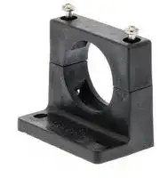


Y92E-A34
Mounting Bracket, E2K-C Sensors, Polyacetal
- Manufacturer: OMRON INDUSTRIAL AUTOMATION
- Product type:
- SVHC: To Be Advised
| Delivery and price | |
|---|---|
| Units per pack | 1 |
| Price | 6.78 € |
| Current stock | 10+ |
| Lead time | 30 days |
**Photoelectric Sensor with Built-in Amplifier E3S**
CSM_E3S_DS_E_ 7 _1
## **General-purpose Photoelectric Sensor for High Quality and Reliable Detection**
Be sure to read _Safety Precautions_ on page 8. ~~a~~
## **Ordering Information**
## **General-purpose Sensors**
|**Sensing method**|**Appearance**<br>~~Ee~~|**Sensing distance**|**Sensing distance**|**Sensing distance**|**Sensing distance**|**Operation mode**<br>~~_~~|**Model**|
|---|---|---|---|---|---|---|---|
|Through-beam*1|~~pt~~<br>~~==~~<br>” ~~=~~<br>~~——~~<br>~~=~~<br>a|||2 m<br>~~==~~||Light-ON/Dark-ON<br>(selectable)|**E3S-2E4**<br>Emitter<br>E3S-2LE4<br>Receiver E3S-2DE4|
|||||||||
|||~~pt~~<br>~~==~~<br>|~~pt~~<br>~~==~~|||||
|||~~pt~~<br>~~==~~<br>|~~pt~~<br>~~==~~|5 m<br>~~==~~<br>~~a~~|5 m<br>~~a~~||**E3S-5E4**<br>Emitter<br>E3S-5LE4<br>Receiver E3S-5DE4|
|||~~==~~<br>|~~==~~|~~==~~||||
|||~~==~~<br>~~=~~|~~==~~|||||
|Retro-reflective||~~==~~<br>~~=~~<br>~~——~~|~~==~~<br>~~——~~|0.1 to 2 m<br>~~==~~<br>~~a~~<br>~~——~~|0.1 to 2 m<br>~~a~~||**E3S-R2E4**|
||||~~==~~<br>~~——~~|~~==~~<br>~~——~~||||
||||~~——~~|||||
|Diffuse-reflective||~~=~~<br>~~——~~|100 mm<br>~~——~~|100 mm<br>~~a~~<br>~~——~~|~~a~~||**E3S-DS10E4**|
|||~~——~~||||||
|||~~——~~<br>~~=~~||||||
|||~~=~~|300 mm|300 mm|-||**E3S-DS30E4**|
|||||||||
|||a||||||
|Through-beam*1|~~||~~<br>9<br>~~=~~<br>~~—~~<br>~~=:~~~~**=**~~<br>~~Oo~~|||2 m<br>|||**E3S-2E41**<br>Emitter<br>E3S-2LE41<br>Receiver E3S-2DE41|
|||~~||~~||||||
|||~~||~~||||||
|||~~| ||~~|~~|~~|5 m<br>~~|~~<br>~~a~~|5 m<br>~~|~~<br>~~a~~||**E3S-5E41 (42)***2<br>Emitter<br>E3S-5LE41 (42)<br>Receiver E3S-5DE41 (42)|
|||~~|~~|~~|~~|~~|~~||||
|||~~|~~<br>~~=~~|~~|~~|||||
|Retro-reflective||~~|~~<br>~~=~~<br>~~—~~|~~|~~<br>~~—~~|0.1 to 2 m<br>~~|~~<br>~~a~~<br>~~—~~|0.1 to 2 m<br>~~|~~<br>~~a~~||**E3S-R2E41**|
||||~~|~~<br>~~—~~|~~|~~<br>~~—~~||||
||||~~—~~|||||
|Diffuse-reflective||~~—~~|100 mm<br>~~—~~<br>~~=:~~|100 mm<br>~~—~~<br>~~=:~~|||**E3S-DS10E41**|
|||~~—~~||||||
|||~~—~~<br>~~=:~~||||||
|||~~=:~~~~**=**~~<br>|300 mm<br>~~=:~~~~**=**~~<br>|300 mm<br>~~=:~~~~**=**~~<br>|~~**=**~~<br>||**E3S-DS30E41 (42)***2|
|||~~=:~~~~**=**~~<br>|~~=:~~~~**=**~~<br>|||||
|||~~=:~~~~**=**~~<br>||||||
|Convergent-reflective<br>(narrow vision field)|~~**=**~~<br>~~Oo ~~|~~**=**~~<br> ~~5~~|30 to 100 mm (variable)<br>~~**=**~~<br>~~5~~|30 to 100 mm (variable)<br>~~**=**~~<br>~~5~~|30 to 100 mm (variable)<br>~~**=**~~<br>~~5~~||**E3S-LS10XE4**|
|Convergent-reflective<br>(wide vision field)||~~**=**~~<br>|50 to 250 mm (variable)<br>~~**=**~~<br>|50 to 250 mm (variable)<br>~~**=**~~<br>|50 to 250 mm (variable)<br>~~**=**~~<br>||**E3S-LS20XE4**|
- *2. The difference between the E3S-@@ (@@@) 41 and E3S-@@ (@@@) 42 is in the lens direction when the Sensor is mounted.
For details, refer to the dimensions that are provided on page 10 for the E3S-5E41, page 11 for the E3S-DS30E41, and page 12 for the E3S-5E42 and E3S-DS30E42.
**1** omRon ~~a~~
**E3S**
## **Ratings and Specifications**
|**Sensing method**|**Sensing method**|**Through-beam**|**Through-beam**|**Retro-re-**<br>**flective**|**Diffuse-reflective**|**Diffuse-reflective**|**Diffuse-reflective**|**Convergent-reflective**|**Convergent-reflective**|
|---|---|---|---|---|---|---|---|---|---|
|**Item**<br>**Model**||**E3S-2E4**<br>**E3S-2E41**|**E3S-5E4**<br>**E3S-5E41**<br>**(42)**|**E3S-R2E4**<br>**E3S-**<br>**R2E41**|**E3S-**<br>**DS10E4**<br>**E3S-**<br>**DS10E41**|**E3S-**<br>**DS30E41**<br>**(42)**|**E3S-**<br>**DS30E4S**|**E3S-**<br>**LS10XE4**|**E3S-**<br>**LS20XE4**|
|**Sensing distance**||2 m|5 m|0.1 to 2 m|100 mm<br>(white paper<br>50 x 50 mm)|300 mm<br>(white paper 100 x 100)||30 to 100 mm<br>Continuously<br>variable<br>(10 x 10 mm)|50 to 250 mm<br>Continuously<br>variable<br>(50 x 75 mm)|
|**Standard sensing**<br>**object**||Opaque: 7-<br>mm dia. min.|Opaque: 11-<br>mm dia. min.|Opaque: 30-<br>mm dia. min.|Transparent, opaque|||||
|**Differential travel**||---|||20% max. of setting distance|||0.5 mm max.<br>at 30 mm|5% max. at 50<br>to 250 mm|
|||||||||3 mm max. at<br>100 mm||
|**Directional angle**||Both emitter and receiver:<br>3°to 10°||3°to 10°|---|||||
|**Light source**<br>**(wavelength)**||Infrared LED<br>(950 nm)||||||RED LED<br>(660 nm)|Infrared LED<br>(950 nm)|
|**Power supply**<br>**voltage**||12 to 24 VDC ±10%, ripple (p-p): 10% max.||||||||
|**Current**<br>**consumption**||50 mA max.<br>(Emitter: 25 mA max.,<br>Receiver: 25 mA max.)||40 mA max.||||||
|**Control output**<br>**(solid-state out-**<br>**put)**||Output current: 1.5 to 4 mA, Load current: 80 mA max. (residual voltage: 2 V max.)➜||||||Refer to page 4.||
|**Response time**||Operate or reset: 3 ms max.||Operate or reset: 1 ms max.||||||
|**Sensitivity**<br>**adjustment**||With an indicator||||||||
|**Ambient**<br>**illumination**<br>**(Receiver side)***||Incandescent lamp: 3,000 lx max.<br>Sunlight: 10,000 lx max.||||||||
|**Ambient**<br>**temperature**||Operating:−25 to 55°C, Storage:−40 to 70°C (with no icing or condensation)||||||||
|**Ambient humidity**||Operating: 35% to 85%, Storage: 35% to 95% (with no condensation)||||||||
|**Insulation**<br>**resistance**||20 MΩmin. at 500 VDC||||||||
|**Dielectric strength**||1,000 VAC, 50/60 Hz for 1 min||||||||
|**Vibration**<br>**resistance**<br>**(destruction)**||10 to 55 Hz, 1.5-mm double amplitude for 2 hours each in X, Y, and Z directions||||||||
|**Shock resistance**<br>**(destruction)**||500 m/s23 times each in X, Y, and Z directions||||||||
|**Degree of**<br>**protection**||IEC IP65|IEC IP67||IEC IP65|IEC IP67||||
|**Connection**<br>**method**||Pre-wired cable (standard length: 2 m)||||||||
|**Indicators**||Light indicator (red), Stability indicator (green)||||||||
|**Material**|**Case**|Polybuty-<br>lene tereph-<br>thalate|Zinc die-cast||Polybuty-<br>lene tereph-<br>thalate|Zinc die-cast||||
||**Lens***|Polycarbonate||||||||
||**Mount-**<br>**ing**<br>**Bracket**|Iron||||||||
*The ambient operating illumination is the illumination that changes the output ±20% at 200 lx. It is not the operational limit.
**2**
**E3S**
## **Engineering Data (Typical)**
## **Parallel Operating Range E3S-2E4 (41)**
## **E3S-5E4 (41) (42)**
**==> picture [326 x 153] intentionally omitted <==**
**----- Start of picture text -----**<br>
100 240<br>E3S-2E41<br>90 220<br>200<br>80<br>180<br>70<br>E3S-2E4 160<br>60<br>140<br>50 120<br>40 100<br>30 80<br>60<br>20<br>Parallel movement distance Y 40 Parallel movement distance Y<br>10<br>20<br>Distance X Distance X<br>0 0.5 1 1.5 2 2.5 3 0 1 2 3 4 5 6 7<br>Distance X (m) Distance X (m)<br>Parallel movement distance Y (mm) Parallel movement distance Y (mm)<br>**----- End of picture text -----**<br>
## **Operating Range E3S-DS10E4 (41)**
## **E3S-DS30E4 (41) (42)**
**==> picture [337 x 299] intentionally omitted <==**
**----- Start of picture text -----**<br>
7.0 10<br>6.0 Optical axis (Y)(−Y) 8 Optical axis (Y)<br>5.0 Operating Operating<br>4.0 Operating distance (X) Standard sensing object(50 x 50 mm) position 6 Operating distance (X) Standard sensing object(100 x 100 mm) position<br>3.0<br>4<br>2.0<br>1.0 2<br>0 20 40 60 80 100 120 140 160 0 20 40 60 80 100 120 140 160<br>1.02.03.0 Operating distance X (mm) 24 Operating distance X (mm)<br>4.0 6<br>5.0 8<br>6.0<br>7.0 10<br>E3S-LS10XE4 E3S-LS20XE4<br>3 20<br>Optical axis (Y) Optical axis (Y)<br>2 Operating distance (X) Standard sensing object(10 x 10 mm)Operating position 1510 distance (X)Operating Standard sensing object(50 x 75 mm)Operating position<br>1 3<br>2 5<br>1 Min. distance set<br>0 20 40 60 80 100 120 140 160 0 0 50 100 150 200 250 300 350<br>Operating distance 12 5 Operating distance<br>1 X (mm) 3 X (mm)<br>10<br>2 Adjust the Adjust the Max. distance set<br>distance: 30 mm distance: 100 mm 15<br>3 20<br>(−Y)<br>(−Y) (−Y)<br>Operating position Y (mm) Operating position Y (mm)<br>Operating position Y (mm) Operating position Y (mm)<br>(Range at minimum setting)<br>**----- End of picture text -----**<br>
## **E3S-LS10XE4**
**3**
**E3S**
**==> picture [512 x 380] intentionally omitted <==**
**----- Start of picture text -----**<br>
Sensing Distance vs. Size of Sensing Object Parallel Operating Range<br>E3S-DS30E4 (41) (42) E3S-R2E4 (41) (42)<br>E3S-DS10E4 (41) E3S-LS20XE4<br>600 The larger the sensing object, 500 100<br>the longer the operating distance.<br>500 80<br>E3S-DS30E4 (1) (2) 400<br>d<br>400<br>60<br>Whitepaper d 300<br>Short edge<br>300 Sensing<br>E3S-DS10E4 (1) object 40<br>200 Whitepaper Longedge<br>200<br>20 Parallel movement<br>Sensing object distance Y<br>Short: Long ratio = 2:3<br>100 100 Distance X<br>0 50 100 150 0 50 100 150 0 0.4 0.8 1.2 1.6 2 2.4 2.8 3.2<br>Side length (one side) of sensing object d (mm) Short edge of sensing object (mm) Distance X (m)<br>Excess Gain vs. Set Distance Load Residual Voltage Characteristics<br>E3S-LS10XE4 E3S-LS3RC4<br>10,0005,000 Received lightoutput peak: •• maximum settingSensitivity adjuster at The characteristics are for 10050 Standard sensing object(white paper) 2.0<br>3,000 30 mm Received lightoutput peak: when the distance where the 30<br>50 mm received light output reaches its peak is set to 30, 50, and Settingdistance 1.5<br>1,000 100 mm using the distance adjuster. 10 Standard sensing object<br>(black carbon)<br>500 Received light output peak: 5<br>300 100 mm 3 1.0<br>100 1 Operating voltage<br>50 Operating level 0.5 0.5<br>30 0.3<br>0 20 40 60 80 100 120 140 160 0 20 28 36 44 52 0 20 50 80 100 150 200<br>Distance (mm) Set distance (mm) Load current (mA)<br>Operating distance (mm) Operating distance (mm) Parallel movement distance Y (mm)<br>Receiver output (mV) Excess Gain Ratio (times) Residual voltage (V)<br>**----- End of picture text -----**<br>
**4**
**E3S**
**I/O Circuit Diagrams**
**==> picture [512 x 267] intentionally omitted <==**
**----- Start of picture text -----**<br>
Item Opera-<br>Wire Power tion Output circuit Timing charts<br>Model color polarity mode<br>Brown *1 12 to 24 VDC<br>Stability<br>Brown + Lightindicator(red) indicator(green)Photo-electricSensor 1.5 to 4 mA Black Load 1 (relay) Lightindicator(red)No incident lightIncident lightOFFON<br>Light-ON maincircuit Z Load 2 *2 Outputtransistor ON<br>OFF<br>Load 1<br>Blue *1 0 V (e.g., relay) Operate<br>Reset (Between brown and black)<br>Blue 0 V Z: Zener diode (Vz = 30 V) Load 2 H<br>*1: Reverse the polarity of the power supply to switch the L (Between blue and black)<br>operating mode.<br>*2: Voltage output (when connecting transistor circuit)<br>E3S<br>Brown *1 0 V<br>Stability<br>Light indicator<br>indicator (green) Incident light<br>Brown 0 V (red) Load 2 *2 No incident light<br>Photo- electric 1.5 to 4 mA Black Lightindicator ON<br>Sensor main Load 1 (red) OFF<br>Dark-ON circuit Z (relay) Outputtransistor ON<br>OFF<br>Load 1<br>Blue *1 12 to 24 VDC (e.g., relay) Operate<br>Reset (Between blue and black)<br>Blue + Z: Zener diode (Vz = 30 V) Load 2 H<br>*1: Reverse the polarity of the power supply to switch the operating mode. L (Between brown and black)<br>*2: Voltage output (when connecting transistor circuit)<br>**----- End of picture text -----**<br>
**5**
**E3S**
## **Connection**
## ● **With Relay Load**
## **Through-beam Sensors**
**Light Interrupted and Load Operating for E3S-2E4 (41) and -5E4 (41) (42)**
**==> picture [229 x 64] intentionally omitted <==**
**----- Start of picture text -----**<br>
Load<br>80 mA max.<br>Pink Black<br>12 to Emitter Receiver 12 to<br>24 V Blue Blue 24 V<br>0 V Brown Brown 0 V<br>**----- End of picture text -----**<br>
## **Retro-reflective Sensors**
**Light Interrupted and Load Operating for E3S-R2E4 (41) (42), -DS10E4(41), and -DS30E4 (41) (42)**
**==> picture [151 x 45] intentionally omitted <==**
**----- Start of picture text -----**<br>
Blue<br>0 V<br>12 to 24 V Brown<br>80 mA max. Black<br>Load Output<br>**----- End of picture text -----**<br>
Note: The indicator will function as a light indication if the Emitter's pink wire is connected to the Receiver's black wire as indicated by the dotted line. The indicator will function as a power indicator if the Emitter's pink wire is connected to the Emitter's blue wire.
## ● **Connection with S3D2 Sensor Controller**
Reverse operation is possible using the signal input switch on the S3D2.
**==> picture [512 x 190] intentionally omitted <==**
**----- Start of picture text -----**<br>
Sensing<br>Through-beam Reflective<br>method<br>Brown Emitter Receiver Brown<br>Black<br>Blue<br>IN1 Black<br>Blue Blue<br>Brown<br>IN<br>Connection 12 V 0 V 12 V 1 0 V<br>method 7 8 9 7 8 9<br>10 11 12 10 11 12<br>4 5 6 4 5 6<br>1 2 3 S3D2 1 2 3 S3D2<br>**----- End of picture text -----**<br>
**6**
**E3S**
## **Adjustment Methods**
## ● **Adjusting the E3S-LS10XE4 Convergent-reflective Sensor**
**==> picture [203 x 107] intentionally omitted <==**
**----- Start of picture text -----**<br>
A<br>Sensitivity adjustment<br>E3S-LS10XE4<br>Distance adjustment scale<br>Distance adjuster<br>* Align the distance adjustment scale<br>with the groove on the Sensor.<br>**----- End of picture text -----**<br>
1. Attach the distance adjustment scale as shown in the figure and set it where the * mark is equal to the sensing distance.
2. Turn the distance adjuster until the red spot is at point A (center of the distance adjustment scale).
3. Remove the distance adjustment scale once the distance has been adjusted. Put a sensing object in place, and then adjust the sensitivity.
## ● **Adjusting the E3S-LS20XE4 Convergent-reflective Sensor**
## **Adjustment Method 1**
Use this method if the sensing object is more reflective than the background.
**==> picture [154 x 109] intentionally omitted <==**
**----- Start of picture text -----**<br>
Sensing object<br>Distance adjuster<br>Background<br>Center object<br>**----- End of picture text -----**<br>
1. Set the sensitivity adjuster to the center as shown in the figure.
2. Turn the distance adjuster counterclockwise until it is fully turned (L to S).
3. Position the sensing object.
4. Slowly turn the distance adjuster clockwise (S to L).
5. Eventually the LIGHT (red) indicator will light. Turning the adjuster further will light the STABILITY (green) indicator. Leave the distance adjuster at this level.
6. Adjust the sensitivity in this state.
## **Adjustment Method 2**
Use this method if the background is more reflective than the sensing object.
**==> picture [151 x 109] intentionally omitted <==**
**----- Start of picture text -----**<br>
Sensing object<br>Distance adjuster<br>Background<br>Center object<br>**----- End of picture text -----**<br>
1. Set the sensitivity adjuster to the center as shown in the figure.
2. Turn the distance adjuster clockwise until it is fully turned (S to L).
3. Remove the sensing object.
4. Slowly turn the distance adjuster counterclockwise (L to S).
5. Eventually the LIGHT (red) indicator will light. Turning the adjuster further will light the STABILITY (green) indicator.
6. Adjust the sensitivity in this state.
**7**
**E3S**
## **Safety Precautions**
## **WARNING**
**This product is not designed or rated for ensuring safety of persons. Do not use it for such purposes.**
## **Precautions for Correct Use**
Do not use the product in atmospheres or environments that exceed product ratings.
If the sensing object has a metallic or shiny surface, the E3SR may not detect it properly. To avoid this situation, place the sensing object so that it is not at right angles to the Photoelectric Sensor.
**==> picture [144 x 75] intentionally omitted <==**
**----- Start of picture text -----**<br>
Reflector<br>Glossy surface Sensing object<br>10° to 20°<br>Create an angle.<br>**----- End of picture text -----**<br>
- **Attaching the E39-S Slit**
- The Slit can be fitted vertically or horizontally as indicated by the dotted line. Make sure that Slits for the Emitter and the Receiver are fitted in the same orientation.
- Place the packing in the supporter and hook the claws on the indentations in the Sensor head.
- If the supporter is contacting the mounting surface, insert a spacer to separate it. (Refer to _Slit Dimensions_ .)
- An operating position accuracy of 0.1 mm max. can be achieved for a Through-beam Sensor without Slits.
**==> picture [187 x 117] intentionally omitted <==**
**----- Start of picture text -----**<br>
Supporter<br>Slit<br>Packing B<br>Sensor head<br>Cut-out section<br>Claws<br>Protrusion<br>Packing A<br>Indentation<br>**----- End of picture text -----**<br>
## **Sensor with Slits**
|**Applicable**<br>**Photoelectric**<br>**Sensor**|**E3S-5E4, -5E41 (42)**|**E3S-5E4, -5E41 (42)**|**E3S-5E4, -5E41 (42)**|**E3S-5E4, -5E41 (42)**|**E3S-2E4, -2E41**|**E3S-2E4, -2E41**|**E3S-2E4, -2E41**|
|---|---|---|---|---|---|---|---|
|**Model**|**E39-S1**||||**E39-S2**|||
|**Item**<br>**Slit**<br>**width**|**0.5 mm**|**1 mm**<br>**2**|**mm**|**4 mm**|**0.5 mm**|**1 mm**|**2 mm**|
|**Sensing**<br>**distance**|230 mm|580 mm<br>12|00 mm|2500 mm|<br>170 mm|420 mm|820 mm|
|**Sensing object**|0.5 mm|1 mm<br>2|mm|4 mm|0.5 mm|1 mm|2 mm|
|**Degree of**<br>**protection**|IP60|||||||
## ● **Sensors with Open-collector Outputs Sensors with Open-collector Outputs**
|**Type**|**Output**<br>**type**|**Output**<br>**transistor**|**Rated**<br>**current**<br>**output**|**Switching**<br>**current**|**Output**<br>**protection**<br>**circuit**|
|---|---|---|---|---|---|
|E|Voltage or<br>current<br>output|NPN|1.5 to<br>4 mA|80 mA max.<br>(sinking)|Provided against<br>an increase in the<br>residual output<br>voltage|
|C|Open-<br>collector<br>output|NPN|---|100 mA<br>max.<br>(sinking)|<br>Provided:<br>Output transistor<br>cutoff|
|B|Open-<br>collector<br>output|PNP|---|100 mA<br>max.<br>(sourcing)|Provided:<br>Output transistor<br>cutoff|
The model numbers are as follows: Example:
E3S-DS10E4 (E type) E3S-DS1C4 (C type) E3S-DS1B4 (B type)
## **C4 (C41, C42) Sensors**
**==> picture [184 x 100] intentionally omitted <==**
**----- Start of picture text -----**<br>
Brown * +V<br>Load<br>(relay)<br>Photo-<br>electric Black (output)<br>Sensor<br>main Z<br>circuit<br>2.2 Ω<br>Blue * 0 V<br>**----- End of picture text -----**<br>
## **C4 (B41, B42) Sensors**
**==> picture [195 x 125] intentionally omitted <==**
**----- Start of picture text -----**<br>
Brown * +V<br>2.2 Ω Z<br>Photo-<br>electric Black (output)<br>Sensor<br>main<br>circuit<br>Load<br>(relay)<br>Blue * 0 V<br>Z: Zener diode (Vz = 30 V)<br>* The operation mode depends on the wiring of the<br>brown and blue lines.<br>**----- End of picture text -----**<br>
Note 1. Only C42 models with die-cast cases are available.
2. The Emitter for a Through-beam C4-type Sensor is the same as the Emitter for an E4-type Sensor. (E.g., E3S-5LE4)
3. When a C- or B- type Sensor experiences a load short-circuit or overload, the output transistor will be turned OFF. Check the load conditions before turning the power back ON.
**8**
**E3S**
## ● **Sensors with Different Orientations**
The E3S-5, E3S-DS30, and E3S-R2 that sense in different directions can be made.
**==> picture [244 x 356] intentionally omitted <==**
**----- Start of picture text -----**<br>
Sensing<br>Sensing direction<br>method<br>E3S-5E43<br>Receiver<br>Emitter<br>Through-<br>beam E3S-5E44<br>Receiver<br>Emitter<br>E3S-DS30E43<br>E3S-R2E43<br>Retro-<br>reflective<br>Diffuse-<br>reflective<br>**----- End of picture text -----**<br>
**9**
**E3S**
(Unit: mm)
## **Dimensions**
Unless otherwise specified, the tolerance class IT16 is used for dimensions in this data sheet.
## **General-purpose Sensors**
**==> picture [509 x 471] intentionally omitted <==**
**----- Start of picture text -----**<br>
E3S-2E4 E3S-2E41<br>4-dia. vinyl-insulated round cable with 2/3 conductors<br>4-dia. vinyl-insulated round cable with 2/3 conductors (Conductor cross section: 0.2 mm [2] , Insulator diameter: 1.1 mm),<br>(Conductor cross section: 0.2 mm [2] , Standard length: 2 m<br>Insulator diameter: 1.1 mm), Weight: Emitter and Receiver, 80 g each<br>Standard length: 2 m<br>Weight: Emitter and Receiver, 80 g each Indicator<br>Indicator Sensitivity adjuster* [2] (50) Sensitivity adjuster* [2]<br>(50) 40<br>18.8 a* [1] 40 5 a* [1] 8.3 32.3 5<br>9.9 Lens: 7 dia. 16 9 11.4 6 dia. 18.8 Lens: 7 dia. 9 11.4 6 dia.<br>“ot_ 15.4 itt AA 12.8 dia. e n 15.4 e + 12.8 dia.<br>16.7 16 4 3.2 9 [16.7] 16.7 16 4 3.2 9 [16.7]<br>1.2 2.7 3.2 4 1.2 3.2 4<br>9 5.5 20 E39-L3 9 5.5 20<br>16.2 30 25.1 Two, M3 30<br>+ 25.1 Two, M3 ** [1][2] The mounting bracket can also be used on side Receiver only. a. + ** [1][2] The mounting bracket can also be used on side Receiver only. v ee a.<br>E3S-5E4 E3S-5E41<br>4-dia. vinyl-insulated round cable with 2/3 conductors<br>(Conductor cross section: 0.2 mm [2] , 4-dia. vinyl-insulated round cable with 2/3 conductors<br>Insulator diameter: 1.1 mm), (Conductor cross section: 0.2 mm [2] , Insulator diameter: 1.1 mm),<br>iS. Standard length: 2 mWeight: Emitter and Receiver, 155 g each Bul: Standard length: 2 mWeight: Emitter and Receiver, 165 g each<br>Indicator (67) Sensitivity adjuster* [2] Indicator Sensitivity adjuster* [2]<br>* [1] (75)<br>23 a 55 7 23 a* [1] 63<br>20 Lens: 11 dia. 11 1 3 20 Lens: 11 dia. 11 1 3 7<br>20.4 So 20 S 13 dia. 20.4 a 20 aw e 13 dia.<br>22.2<br>22.2<br>a 20 e 5 ee ) 4.2 | , 20 | 5 eer p= 4.2<br>1.6 2.1R 4.2 5 2.1R 1.6 2.1R 4.2 5 2.1R<br>1 2 25.4<br>a 22(32) Two, M4slotted hexagonal bolts | tH ** [1][2] The mounting bracket can also be used on side Receiver only. eH 6.5 39 X 1.9 E39-L6 a. + 1 2 \ (32) _. Two, M4slotted hexagonal bolts** [1][2] The mounting bracket can also be used on side Receiver only. a 18.6 ‘i| 6.5 25.439 i 1.9 a.<br>**----- End of picture text -----**<br>
Note: Models numbers for Through-beam Sensors (E3S-@E4, E3S-@E41) are for sets that include both the Emitter and Receiver.
The model number of the Emitter is expressed by adding "L" to the set model number (example: E3S-2LE4), the model number of the Receiver, by adding "D" (example: E3S-2DE4.) Refer to Ordering Information to confirm model numbers for Emitter and Receivers.
**10**
**E3S**
## **E3S-DS10E4**
**==> picture [59 x 8] intentionally omitted <==**
**----- Start of picture text -----**<br>
E3S-DS10E41<br>**----- End of picture text -----**<br>
**==> picture [508 x 425] intentionally omitted <==**
**----- Start of picture text -----**<br>
4-dia. vinyl-insulated round cable with 3 conductors<br>(Conductor cross section: 0.2 mm [2] , Insulator diameter: 1.1 mm), 4-dia. vinyl-insulated round cable with 3 conductors<br>Standard length: 2 m (Conductor cross section: 0.2 mm [2] , Insulator diameter: 1.1 mm),<br>Weight: Approx. 80 g Standard length: 2 m<br>Weight: Approx. 80 g<br>Indicator Sensitivity adjuster<br>Lens: 7 x 1310.521 a* iat 16 40(50)9 11.4 7 5 Sensitivity a . * 52111 Lens: 7 x 13Emitter —— 5.5 4029.5(50) — 5<br>adjuster Receiver<br>15.4 I S or 6 dia. 12.8 dia. = =<br>15.4 6 dia.12.8 dia.<br>16.7<br>{ 16 4 we a , 3.2 9 [16.7] Va V 16.7 16 4 so 9 [16.7]<br>3.2<br>1.2 Emitter 3.2 4<br>1.2 3.2 4<br>9 Receiver 5.5 Ml 20 9 Indicator 5.5 " 20<br>16.8 30<br>27.3 Two, M3 27.3 Two, M3 30<br>* The mounting bracket can also be used on side a. * The mounting bracket can also be used on side a.<br>E3S-R2E4 E3S-R2E41<br>E3S-DS30E4 E3S-DS30E41<br>4-dia. vinyl-insulated round cable with 3 conductors 4-dia. vinyl-insulated round cable with 3 conductors<br>(Conductor cross section: 0.2 mm [2] , Insulator diameter: 1.1 mm), (Conductor cross section: 0.2 mm [2] , Insulator diameter: 1.1 mm),<br>Standard length: 2 m Standard length: 2 m<br>Weight: Approx. 155 g Weight: Approx. 165 g<br>Indicator Sensitivity adjuster Indicator Sensitivity adjuster<br>a* : 2320 55(67) a* 23 Lens: 10 x 15 63(75) 7<br>7.1 Lens: 10 x 15 7 20 Emitter 11 13<br>11 13 Receiver<br>20.4 ~ ry 20 _ SOY a 13 dia. 20.4 To = 20 hmmcl ee % | Fe 13 dia.<br>22.2<br>22.2<br>5<br>20 5 4.2 20 4.2<br>1.6 Emitter 2.1R4.2 5 1.6 2.1R4.2 5 2.1R<br>1 2 Receiver 6.5 25.4 2.1R 1 2 1 8.6<br>2224.9 Two, M4slotted hexagonal bolts 39 1.9 (32) Two, M4slotted hexagonal bolts 6.5 25.439 1.9<br>(32) * The mounting bracket can also be used on side a.<br>* The mounting bracket can also be used on side a.<br>**----- End of picture text -----**<br>
**E3S-R2E4 E3S-DS30E4**
**11**
**E3S**
## **E3S-5E42**
**==> picture [487 x 224] intentionally omitted <==**
**----- Start of picture text -----**<br>
4-dia. vinyl-insulated round cable with 2/3 conductors<br>(Conductor cross section: 0.2 mm [2] ,<br>Insulator diameter: 1.1 mm),<br>Standard length: 2 m Receiver Indicator Sensitivity adjuster<br>Weight: Approx. 165 g<br>(75)<br>Lens: 11 dia. 18.6 a* 23 63 7<br>20 11 13<br>20.4 20 13 dia.<br>10.2<br>22.2<br>20 5 4.2<br>Indicator<br>Emitter 2320 63(75) 24 7 1.6 1 2 6.5 2.1R4.225.4 5 2.1R<br>(32) Two, M4 39 1.9<br>slotted hexagonal bolts<br>20.4 20 13 dia.<br>10.2<br>22.2<br>20 5 4.2<br>1.6 1 2 (32) Two, M4slotted hexagonal bolts6.5 2.1R4.225.439 5 2.1R1.9 Lens: 11 dia.* The mounting bracket can also be used on side 18.6 a.<br>**----- End of picture text -----**<br>
**==> picture [509 x 280] intentionally omitted <==**
**----- Start of picture text -----**<br>
E3S-R2E42 E3S-LS10XE4<br>E3S-DS30E42 E3S-LS20XE4 4-dia. vinyl-insulated round cable with 3 conductors<br>(Conductor cross section: 0.2 mm [2] , Insulator diameter: 1.1 mm),<br>Standard length: 2 m<br>4-dia. vinyl-insulated round cable with 3 conductors Weight: Approx. 225 g<br>(Conductor cross section: 0.2 mm [2] , Insulator diameter: 1.1 mm), 34<br>Standard length: 2 m<br>Weight: Approx. 165 g 20 2.1R<br>Indicator<br>21.5<br>18.6<br>11<br>Lens:<br>10 x 15 24 4.2<br>5<br>tH x Ue ee<br>1) —$® Ae \io am<br>17<br>7.1 IndicatorEmitterReceiver(75) Sensitivity adjuster Two, M4slotted hexagonal bolts Lens: 14 x 47 a* a 26 1120 Sensitivity adjuster6 Distance adjuster<br>23 63 5<br>7<br>20 11 1 3<br>Emitter<br>20.4 SS. 20 e ee. 13 dia. Optical axis « 6 Le 8 dia. 45 55<br>10.2<br>70<br>_s 22.2 r | E OF FBS | Receiver | 4.9 z|<br>20 5 4.2 45<br>1.6 2.1R 4.2 5 2.1R 1.6 Two,<br>1 2 25.4 4.4 dia.<br>6.5 1.9<br>+ (32) Two, M4 s ee 39 | a 16 )—€_|_*<br>slotted hexagonal bolts ee EN 50<br>* The mounting bracket can also be used on side a.<br>6<br>3 4.2<br>**----- End of picture text -----**<br>
Note: Models numbers for Through-beam Sensors (E3S-5E42) are for sets that include both the Emitter and Receiver.
The model number of the Emitter is expressed by adding "L" to the set model number (example: E3S-5LE42), the model number of the Receiver, by adding "D" (example: E3S-5DE42.) Refer to Ordering Information to confirm model numbers for Emitter and Receivers.
## **Mounting Hole Dimensions**
**E3S-2E4 E3S-LS10XE4** Two, M3 **E3S-5E4 E3S-DS30E4** Two, M4 **E3S-2E41 E3S-LS20XE4 E3S-5E41 E3S-DS30E41 (42) E3S-DS10E4 E3S-R2E4** 25.4 **E3S-DS10E41** ttt 20 **E3S-R2E41 (42)** Ct
**12** omron ~~a~~
**E3S**
## **Accessories (Order Separately)**
## **Special Mounting Bracket E39-L2**
**==> picture [512 x 270] intentionally omitted <==**
**----- Start of picture text -----**<br>
E39-L2 92.1<br>82.1<br>Mounting Holes<br>Two, M4<br>10.2<br>20.2<br>25.4<br>5<br>41 25.4<br>4.2<br>4.2 Two, M4 slotted Applicable models:<br>hexagonal bolts E3S-5E41<br>E3S-R2E41<br>5.6 2.1R 5 E3S-DS30E41<br>25 25.4 9 29.1<br>E39-L4<br>68.5<br>60.8<br>Mounting Holes<br>15.70 Two, M3<br>33 20 4 20<br>3.2<br>3.2<br>5 Two, M3<br>204 20 4 28.5 Applicable models:E3S-2E41E3S-DS10E41<br>**----- End of picture text -----**<br>
## **Reflector E39-R1 (Provided with the E3S-R2E4(41) Retro-reflective Reflector.)**
**==> picture [216 x 109] intentionally omitted <==**
**----- Start of picture text -----**<br>
40.3<br>Two, 3.5 dia. 34 7.5<br>7<br>59.9 52<br>Material:<br>Reflective surface: Acrylic 8<br>Rear surface: ABS<br>1.6 2.7<br>**----- End of picture text -----**<br>
**Sensitivity Adjuster (Provided) E39-G1**
**==> picture [202 x 93] intentionally omitted <==**
**----- Start of picture text -----**<br>
4<br>9.3 dia. 13 dia.<br>Applicable models:<br>Provided with the E3S-5E4(41), E3S-DS30E4(41), E3S-R2E4(41).<br>Note: Cannot be used for the E3S-DS10E4 (41).<br>**----- End of picture text -----**<br>
**13**
**E3S**
**Slit (Order Separately)** 10.5 **Slit E39-S2 E39-S2** 13 1.8 Applicable E3S-2E4 Sensors E3S-2E41 17.8 1.2 Note 1. Three sets of slits are provided: 17.9 6.5 x 0.5 mm, 6.5 x 1 mm and 6.5 x (16.7) 2 mm 2. One set consists of two slits, one E39-S2 each for the Emitter and Receiver. *Spacer **E39-S1 Slit E39-S1** 8.3 Applicable E3S-5E4 20 2.1 Sensors E3S-5E41 Note 1. Four sets of slits are provided: 1.2 11 x 0.5 mm, 11 x 1 mm, 11 x 2 mm, 22.4 and 11 x 4 mm 23.4 2. One set consists of two slits, one ig ~~h~~ (22.2) Eso each for the Emitter and Receiver. ~~—~~ E39-S2 ~~ee~~ _ Eee b= Note: The dimensions in parentheses are for when the Spacer is not used. *Spacer *With the E3S-2E4 (41), use the Spacer as shown in the figure above so that the supporter and Mounting Bracket will not be struck when the optical axis is adjusted.
With the E3S-5E4 (41), the Spacer is not particularly required. Use the Spacer, however, to directly mount both the E3S-2E4 (41) and -5E4 (41).
**In the interest of product improvement, specifications are subject to change without notice.**
**14**
## **Read and Understand This Catalog**
Please read and understand this catalog before purchasing the products. Please consult your OMRON representative if you have any questions or comments.
## **Warranty and Limitations of Liability**
- **WARRANTY** OMRON's exclusive warranty is that the products are free from defects in materials and workmanship for a period of one year (or other period if specified) from date of sale by OMRON.
OMRON MAKES NO WARRANTY OR REPRESENTATION, EXPRESS OR IMPLIED, REGARDING NON-INFRINGEMENT, MERCHANTABILITY, OR FITNESS FOR PARTICULAR PURPOSE OF THE PRODUCTS. ANY BUYER OR USER ACKNOWLEDGES THAT THE BUYER OR USER ALONE HAS DETERMINED THAT THE PRODUCTS WILL SUITABLY MEET THE REQUIREMENTS OF THEIR INTENDED USE. OMRON DISCLAIMS ALL OTHER WARRANTIES, EXPRESS OR IMPLIED.
**==> picture [479 x 33] intentionally omitted <==**
**----- Start of picture text -----**<br>
LIMITATIONS OF LIABILITY<br>OMRON SHALL NOT BE RESPONSIBLE FOR SPECIAL, INDIRECT, OR CONSEQUENTIAL DAMAGES, LOSS OF PROFITS OR COMMERCIAL LOSS<br>IN ANY WAY CONNECTED WITH THE PRODUCTS, WHETHER SUCH CLAIM IS BASED ON CONTRACT, WARRANTY, NEGLIGENCE, OR STRICT<br>LIABILITY.<br>**----- End of picture text -----**<br>
In no event shall the responsibility of OMRON for any act exceed the individual price of the product on which liability is asserted. IN NO EVENT SHALL OMRON BE RESPONSIBLE FOR WARRANTY, REPAIR, OR OTHER CLAIMS REGARDING THE PRODUCTS UNLESS OMRON'S ANALYSIS CONFIRMS THAT THE PRODUCTS WERE PROPERLY HANDLED, STORED, INSTALLED, AND MAINTAINED AND NOT SUBJECT TO CONTAMINATION, ABUSE, MISUSE, OR INAPPROPRIATE MODIFICATION OR REPAIR.
## **Application Considerations**
**==> picture [508 x 457] intentionally omitted <==**
**----- Start of picture text -----**<br>
SUITABILITY FOR USE<br>OMRON shall not be responsible for conformity with any standards, codes, or regulations that apply to the combination of products in the customer's<br>application or use of the products.<br>At the customer's request, OMRON will provide applicable third party certification documents identifying ratings and limitations of use that apply to the<br>products. This information by itself is not sufficient for a complete determination of the suitability of the products in combination with the end product,<br>machine, system, or other application or use.<br>The following are some examples of applications for which particular attention must be given. This is not intended to be an exhaustive list of all possible<br>uses of the products, nor is it intended to imply that the uses listed may be suitable for the products:<br> Outdoor use, uses involving potential chemical contamination or electrical interference, or conditions or uses not described in this catalog.<br> Nuclear energy control systems, combustion systems, railroad systems, aviation systems, medical equipment, amusement machines, vehicles,<br>safety equipment, and installations subject to separate industry or government regulations.<br> Systems, machines, and equipment that could present a risk to life or property.<br>Please know and observe all prohibitions of use applicable to the products.<br>NEVER USE THE PRODUCTS FOR AN APPLICATION INVOLVING SERIOUS RISK TO LIFE OR PROPERTY WITHOUT ENSURING THAT THE<br>SYSTEM AS A WHOLE HAS BEEN DESIGNED TO ADDRESS THE RISKS, AND THAT THE OMRON PRODUCTS ARE PROPERLY RATED AND<br>INSTALLED FOR THE INTENDED USE WITHIN THE OVERALL EQUIPMENT OR SYSTEM.<br>PROGRAMMABLE PRODUCTS<br>OMRON shall not be responsible for the user's programming of a programmable product, or any consequence thereof.<br>Disclaimers<br>CHANGE IN SPECIFICATIONS<br>Product specifications and accessories may be changed at any time based on improvements and other reasons.<br>It is our practice to change model numbers when published ratings or features are changed, or when significant construction changes are made.<br>However, some specifications of the products may be changed without any notice. When in doubt, special model numbers may be assigned to fix or<br>establish key specifications for your application on your request. Please consult with your OMRON representative at any time to confirm actual<br>specifications of purchased products.<br>DIMENSIONS AND WEIGHTS<br>Dimensions and weights are nominal and are not to be used for manufacturing purposes, even when tolerances are shown.<br>PERFORMANCE DATA<br>Performance data given in this catalog is provided as a guide for the user in determining suitability and does not constitute a warranty. It may represent the<br>result of OMRON’s test conditions, and the users must correlate it to actual application requirements. Actual performance is subject to the OMRON<br>Warranty and Limitations of Liability.<br>ERRORS AND OMISSIONS<br>The information in this document has been carefully checked and is believed to be accurate; however, no responsibility is assumed for clerical,<br>typographical, or proofreading errors, or omissions.<br>2011.9<br>In the interest of product improvement, specifications are subject to change without notice.<br>**----- End of picture text -----**<br>
## **OMRON Corporation Industrial Automation Company**
**http://www.ia.omron.com/**
(c)Copyright OMRON Corporation 2011 All Right Reserved.
Updated at June 9, 2026
With a legacy spanning over 80 years, Omron Industrial Automation is a globally recognized leader in the manufacture of advanced industrial control and automation components. Renowned for their reliability and engineering excellence, Omron delivers comprehensive solutions that enhance efficiency, machine safety, and precision across a wide range of manufacturing environments. Our extensive portfolio of Omron products is heavily focused on their industry-leading sensing and switching technologies. We offer a vast selection of sensors, excelling specifically in high-performance proximity sensors, light sensors, and temperature sensors. Complementing this range are robust switching solutions, featuring a deep inventory of power relays, solid-state relays, safety relays, and essential relay accessories designed for demanding operational requirements. Beyond sensing and switching, Omron is highly regarded for its precision automation and process control equipment. Our selection features highly accurate temperature controllers, versatile process controllers, and sophisticated panel displays and instrumentation. To support these fundamental systems, we also supply dependable Omron power supplies, notably AC/DC converters, alongside vital connectivity components like DIN rail terminal blocks to ensure secure, efficient, and complete industrial setups.
About Novapart
Novapart is a B2B electronic component broker specialising in stock shortages and cost reduction. We source hard-to-find parts and identify compliant alternatives across a catalogue of 410,000+ components from 500+ manufacturers.
Learn more →Stock Shortage Specialist
When a component is unavailable, discontinued or has an unacceptable lead time, we tap into our network of vetted European and Asian distributors to source what you need — without compromising on quality or traceability.
Request a quote →Compliant Alternatives
We identify pin-to-pin, electrically equivalent substitutes that meet the same certifications (RoHS, AEC-Q100, REACH) as your original specification — validated against datasheets, not just part numbers. Often at a lower cost.
BOM Analysis service →