
Image not available
Illustrative purposes only

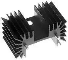
WMHPHS-25A
Heat Sink, WMHP Resistor, 0.5 °C/W, TO-220, TO-247, 25.4 mm, 25 mm, 42 mm
⚠️ Reference pricing provided. In case of supply shortages, we will connect you with our trusted procurement partners to ensure your project's continuity.
- Manufacturer: TT ELECTRONICS
- Product type: Natural Convection Heat Sinks
- Packages Cooled: TO-220, TO-247
- Heat Sink Material: Aluminium Alloy
- Thermal Resistance: 0.5°C/W
- External Width - Metric: 25.4mm
- External Height - Metric: 25mm
- External Length - Metric: 42mm
- External Width - Imperial: 1"
- External Height - Imperial: 0.98"
- External Length - Imperial: 1.65"
| Delivery and price | |
|---|---|
| Units per pack | 250 |
| Price | 1.97 € |
| Current stock | 10+ |
| Lead time | 30 days |
Datasheet

**Resistors**

## **Heatsink for WMHP Series High Power Resistors**

## **WMHP-HS Series**

- For TO-220 and TO-247 packages

- Ideal for use with WMHP series power resistors Ridged fins for higher surface area with low mass

- Low thermal resistance

- Black anodised finish Solderable pins for robust PCB mounting

All parts are Pb-free and comply with EU Directive 2011/65/EU (RoHS2)

## Functional Data

|Functional Data||
|---|---|
||WMHP-HS-25|
|Height                                                                                                                   mm|25.4|
|Compatible package type|TO-220, TO-247|
|Compatible resistors|WMHP20, WMHP35, WMHP50, WMHP100|
|Surface area                                                                                                       mm2|10,155|
|Weight                                                                                                                       g|22.7|
|Thermal resistance, forced air 5m/s                                                            °C/W|0.5|


## Physical Data

**==> picture [87 x 143] intentionally omitted <==**

**----- Start of picture text -----**<br>
Dimensions (mm)<br>H<br>Type<br>nom<br>WMHP-HS-25 25.4<br>**----- End of picture text -----**<br>


## **Construction**

The heatsink is extruded from 6063-T5 aluminium cut to length, drilled and then black anodised. Two 2.3mm diameter brass pins with 100% tin finish are interference fitted.

## **General Note**

BI Technologies    IRC    Welwyn

TT Electronics reserves the right to make changes in product specification without notice or liability. All information is subject to TT Electronics’ own data and is considered accurate at time of going to print.

www.ttelectronics.com/resistors

© TT Electronics plc

09.17

**WMHP-HS Series**

## **Heatsink for WMHP Series High Power Resistors**

## Thermal Performance - Data

**==> picture [476 x 494] intentionally omitted <==**

**----- Start of picture text -----**<br>
Sa Z4<br>3 — :<br>: : a : |<br>ESSEe<br>0 1 2 3 4 5 0 1 2 3 4<br>Air Velocity (m/s) Air Velocity (m/s)<br>Natural Convection - Standard Test Natural Convection - PCB Mounted<br>Temperature Rise of Mounting Surface above Ambient Temperature Rise of Mounting Surface above Ambient<br>a0160 | 160an TT. |<br>< 120 || e 120 L<br>2 co at 3°<br>§ v0 | g Pa<br>Eg£ A | :°£ 60 ra<br>20<br>) 5 10 15 20 0<br>Heat Dissipation (W) 0 5 10 15<br>Heat Dissipation (W)<br>Duct to  y Mounting Surface Temperature  Mounting Surface Temperature<br>constrain  y Probe Point  Probe Point<br>airflow  4<br>y UP  UP<br>y<br>y<br>y<br>y<br>y<br>y l | :<br>y<br>é<br>These data relate to a standard heatsink test condition  These data relate to a normal application condition<br>with unobstructed fins and ducted airflow, and are  with fins obstructed by a PCB and non-ducted airflow,<br>included for comparison purposes.  and may be used for practical thermal design.<br>**----- End of picture text -----**<br>


**General Note** TT Electronics reserves the right to make changes in product specification without notice or liability. All information is subject to TT Electronics’ own data and is considered accurate at time of going to print.

BI Technologies    IRC    Welwyn

www.ttelectronics.com/resistors

© TT Electronics plc

09.17

**WMHP-HS Series**

## **Heatsink for WMHP Series High Power Resistors**

## Application Notes

## **Steady State Thermal Calculations**

A simple thermal model of a power resistor on a heatsink is shown, in which temperature rise may be calculated from the product of power dissipated and thermal impedance. Maximum **P** , **TE** and **RθEF** values for WMHP are given below.

|Type|**P**Max @**TF**=25°C<br>(W)|**TE**Max<br>(°C)|**RθEF**<br>(°C/W)|
|---|---|---|---|
|WMHP20|20|150|6.25|
|WMHP35|35||3.57|
|WMHP50|50||2.50|
|WMHP100|100|175|1.50|


**==> picture [219 x 159] intentionally omitted <==**

**----- Start of picture text -----**<br>
TE  = Temperature of resistor element<br>P  = Power dissipated<br>RθEF  = Thermal resistance element to flange of WMHP<br>TF  = Temperature of resistor flange<br>RθFH  = Thermal resistance flange to heatsink of thermal<br>interface<br>TH  = Temperature of heatsink mounting surface<br>RθHA  = Thermal resistance heatsink to ambient of WMHP-HS<br>TA  = Temperature of ambient air<br>P  RθEF RθFH RθHA<br>TE TF TH TA<br>Figure 1. Thermal model of WMHP and WMHP-HS<br>**----- End of picture text -----**<br>


The maximum value of **P** for **T T F** >25°C is a function of **F** and is shown in the WMHP datasheet de-rating graph. The value of **R θFH** depends on the thermal interface material. For thermal paste a typical figure is around 1°C/W. For forced air cooling the value of **RθHA** is shown as a function of air velocity in the Forced Air Cooling graph. For **R P** natural convection **θHA** is slightly non-linear, as shown in the Natural Convection graph. The standard figure at = 20W is given, and for lower powers you can directly read the heatsink temperature rise **TH** – **TA** .

**Example:** WMHP20 is dissipating 5W at an ambient air temperature of 30°C. The WMHP-HS is PCB mounted and cooled by natural convection. Is the maximum resistor element temperature acceptable? **TA** = 30°C, and **TH** – **TA** = 50°C at **P** = 5W. Therefore **TH** = 80°C. Assuming **RθFH** = 1°C/W, **TF** = 85°C. Therefore **TE** = 85°C + 6.25°C/W x 5W = 116°C. This is acceptable as it is below 150°C.

## **Dynamic Thermal Calculations**

In some applications such as inrush current control, the dissipation of power is of limited duration. If the duration is between about 30s and 10 minutes then the dynamic temperature rise graph may be used to determine the highest value of **TH** achieved at the end of **T** and **T** is then the same the loading. The derivation of **F E** as for the steady state case.

**==> picture [85 x 27] intentionally omitted <==**

**----- Start of picture text -----**<br>
Forced Air 2.5m/s: τ = 50 seconds<br>Natural Convection: τ = 2.4 minutes<br>**----- End of picture text -----**<br>


If power is reapplied before the heatsink has fully cooled, then cumulative heating must be accounted for. This can generally be ignored if the mean power dissipation is below 10% of the maximum permissible steady state dissipation.

For durations below about 30s, the best guide is the Pulse Performance graph on the WMHP datasheet.

**General Note** TT Electronics reserves the right to make changes in product specification without notice or liability. All information is subject to TT Electronics’ own data and is considered accurate at time of going to print.

BI Technologies    IRC    Welwyn

www.ttelectronics.com/resistors

© TT Electronics plc

09.17

## **Heatsink for WMHP Series High Power Resistors**

## **WMHP-HS Series**

## **Layout Design and Assembly**

A TO-220 package may be fitted to either side of the heatsink; thermal performance is the same for both mounting surfaces. Furthermore, two packages may be fitted, one to each side, provided the total power dissipated does not exceed the rating of either. A TO-247 package can only be fitted to the wider of the two mounting surfaces.

If other heat generating components are present nearby, the heatsink orientation should be chosen so that the side with more fins is located away from the heat source.

**==> picture [240 x 7] intentionally omitted <==**

**----- Start of picture text -----**<br>
Figure 2. Typical mounting arrangement with TO-220 package (fixing not shown).<br>**----- End of picture text -----**<br>


The package should be fitted to the heatsink using a suitable thermal interface material, for example a thermal pad or paste such as Dow Corning DC340. It should be secured with an M3 mounting screw tightened to give void-free thermal contact and to a maximum torque of 0.9Nm.

The pins are intended for soldering to traces on the reverse side of the PCB. Care should be taken to provide sufficient heat to achieve these solder joints.

A 3-D drawing of this heatsink may be downloaded from http://www.ttelectronics.com/themes/ttelectronics/downloads/resistors/3d_drawings/WMHP-HS.zip

This product is designed for use with WMHP series power resistors, but is suitable for any components in the same or similar package style. For WMHP product data see http://www.ttelectronics.com/sites/default/files/resistors-datasheets/WMHP.pdf

## **Ordering Procedure**

**Example: WMHP-HS-25AB005** (WMHP-HS, 25.4mm high, black anodized, Pb-free)

|**Example: WMHP-HS-25AB005**(WMHP-HS, 25.4mm high, black anodized, Pb-free)|(WMHP-HS, 25.4mm high, black anodized, Pb-free)|(WMHP-HS, 25.4mm high, black anodized, Pb-free)|
|---|---|---|
|**W**<br>**M**<br>**H**<br>**P**<br>**-**<br>**H**<br>**S**<br>**-**<br>**2**<br>**5**<br>**A**<br>**B**<br>**0**<br>**0**<br>**5**<br>**1**<br>**2**<br>**3**<br>**4**<br>~~ODOOOOOOODOOOOOOO~~<br>~~|~~<br>~~|~~<br>~~|~~|||
|**1**<br>**2**<br>**3**<br>**5**|||
|**Series**<br>**Height**<br>**Finish**<br>**Packing**|||
|WMHP-HS<br>25 = 24.4mm<br>A = Black anodised B005 WHMP-HS-25<br>5||Bulk 50/box|


BI Technologies    IRC    Welwyn

**General Note**

TT Electronics reserves the right to make changes in product specification without notice or liability. All information is subject to TT Electronics’ own data and is considered accurate at time of going to print.

www.ttelectronics.com/resistors

© TT Electronics plc

09.17
Updated at February 9, 2023
About Novapart
Novapart is a B2B electronic component broker specialising in stock shortages and cost reduction. We source hard-to-find parts and identify compliant alternatives across a catalogue of 410,000+ components from 500+ manufacturers.
Learn more →Stock Shortage Specialist
When a component is unavailable, discontinued or has an unacceptable lead time, we tap into our network of vetted European and Asian distributors to source what you need — without compromising on quality or traceability.
Request a quote →Compliant Alternatives
We identify pin-to-pin, electrically equivalent substitutes that meet the same certifications (RoHS, AEC-Q100, REACH) as your original specification — validated against datasheets, not just part numbers. Often at a lower cost.
BOM Analysis service →