
Image not available
Illustrative purposes only

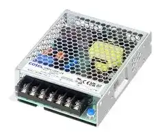
WMA100F-24
AC/DC Enclosed Power Supply (PSU), ITE & Medical, 1 Outputs, 103.2 W, 24 V, 4.3 A
⚠️ Reference pricing provided. In case of supply shortages, we will connect you with our trusted procurement partners to ensure your project's continuity.
- Manufacturer: COSEL
- Product type: AC / DC Enclosed Power Supplies
- SVHC: Lead (04-Feb-2026)
- Product Range: WMA Series
- No. of Outputs: 1Outputs
- Output Power Max: 103.2W
- Current, Output 4: -
- Input Voltage VAC: 85V AC to 264V AC
- Power Supply Output Type: Fixed
- Output Current - Output 1: 4.3A
- Output Current - Output 2: -
- Output Current - Output 3: -
- Output Voltage - Output 1: 24V
- Output Voltage - Output 2: -
- Output Voltage - Output 3: -
- Output Voltage - Output 4: -
- Power Supply Applications: ITE & Medical
| Delivery and price | |
|---|---|
| Units per pack | 10 |
| Price | 24.29 € |
| Current stock | 10+ |
| Lead time | 30 days |
Datasheet

**AC-DC Power Supplies Medical Type**

**WMA**

Medical World wide Cost Safety EMI Inrush OCP OVP electric Effective Approvals current equipment limiting

## **WMA-series**

## **Feature**

For medical electric equipment (ANSI/AAMI ES60601-1, EN60601-1 3rd) Medical Isolation Grade 2MOPP 4kV isolation Low-profile Economical design Complies with SEMI F47(See Instruction Manual)

## **Safety agency approvals**

ANSI/AAMI ES60601-1, EN60601-1 3rd, C-UL (CAN/CSA-C22.2 No.60601-1), UL62368-1, EN62368-1, C-UL (CAN/CSA-C22.2 No.62368-1), EN61558-2-16 (OVC III)

## **CE marking**

Low Voltage Directive RoHS Directive

## **UKCA marking**

Electrical Equipment Safety Regulations RoHS Regulations

**5-year warranty** (See Instruction Manual)

## **EMI**

Complies with CISPR11-B, CISPR32-B, EN55011-B, EN55032-B, FCC Part 15-B, FCC Part 18-B

**EMS Compliance** : EN61204-3, EN61000-6-2 IEC60601-1-2 (2014), EN60601-1-2 (2015)

EN61000-4-2 EN61000-4-3 EN61000-4-4 EN61000-4-5 EN61000-4-6 EN61000-4-8 EN61000-4-11

**WMA-1**

November 10, 2023

**AC-DC Power Supplies Medical Type WMA35F WMA**[|] ~~_~~

**Ordering information - - WM A 35 F** O O

—

1 2

3 4 5 6 1Series name 2Single output 3Output wattage 4Universal input 5Output voltage 6Optional : *6 C : With Coating G : Low leakage current J1 : VH(J.S.T.)connector type J4 : EP(Tyco)connector type T1 : Horizontal terminal block

|**MODEL**<br>~~_~~<br>~~ae~~|**MODEL**<br>~~_~~<br>~~ae~~|**WMA35F-5**<br>~~Cd~~<br>~~ae~~|**WMA35F-12**<br>~~Cd~~|**WMA35F-24**<br>~~Cd~~|
|---|---|---|---|---|
|**VOLTAGE[V]**<br>~~ae~~|||||
|**CURRENT[A]**<br>~~ae~~<br>~~pF~~<br>~~SS~~<br>~~2~~|**ACIN 115V** <br>~~ae~~<br>~~pF~~||||
||**ACIN 230V** <br>~~ae~~<br>~~pF~~<br>~~—————~~<br>||||
|**FREQUENCY[Hz]**<br>~~SS—————~~<br>~~2~~|||||
|**EFFICIENCY[%]**<br>~~SS~~<br>~~2 ~~|**ACIN 115V** <br>~~—————~~<br>~~eee~~|79typ<br>~~—————~~<br>~~eee~~|84typ<br>~~[CT~~<br>~~es~~|86typ<br>~~[CT~~|
||**ACIN 230V** <br>~~—————~~<br> ~~eee~~|82typ<br>~~—————~~<br>~~eee~~|86typ<br>~~[CT~~<br>~~es~~|88typ<br>~~[CT~~|
|**INRUSH CURRENT[A]**<br>~~SS ~~<br>~~2 ~~<br>~~PE~~<br>~~-—~~|**ACIN 115V** <br> ~~—————~~<br> <br>~~a~~<br>~~PE~~||||
||**ACIN 230V** <br>~~PE~~<br>~~-—~~||||
|**LEAKAGE**<br>**CURRENT[mA]**<br>~~-—~~<br>~~| ~~<br>~~————————————~~|**ACIN 115V** <br>~~-—~~<br>||||
||**ACIN 240V** <br>~~-—~~<br> <br>~~————————————~~||||
|**VOLTAGE[V]**<br>~~-—~~<br> <br>~~————————————~~<br>~~es~~||5<br> ~~a~~<br>~~————————————~~<br>~~ee~~|12<br>~~a~~<br>~~a~~<br>~~————————————~~<br>~~ee~~|24<br>~~—~~<br>~~ee~~|
|**CURRENT[A]**<br> <br>~~————————————~~<br>~~es~~<br>~~**—**—~~||7<br> ~~a~~<br>~~————————————~~<br>~~ee~~|3<br>~~a~~<br>~~————————————~~<br>~~ee~~|1.5<br>~~ee~~|
|**WATTAGE[W]**<br>~~————————————~~<br>~~es~~<br>~~**—**—~~||35<br>~~————————————~~<br>~~ee~~|36<br>~~————————————~~<br>~~ee~~|36<br>~~ee~~|
|**LINE REGULATION[mV]**<br>*1 <br>~~————————————~~<br>~~es~~<br>~~**—**—~~||50max<br>~~————————————~~<br>~~ee~~|120max<br>~~————————————~~<br>~~ee~~|240max<br>~~ee~~|
|**LOAD REGULATION[mV]** *1 <br>~~————————————~~<br>~~es~~<br>~~**—**—~~<br>~~—~~||50max<br>~~————————————~~<br>~~ee~~|120max<br>~~————————————~~<br>~~ee~~|240max<br>~~ee~~<br>~~oT~~|
|**RIPPLE NOISE[mVp-p]** *2 <br>~~es~~<br>~~**—**—~~<br>~~—~~<br>~~—~~|**lo=100%** <br>~~es ~~<br>~~—~~<br>~~—~~<br>~~—~~||||
|**TEMPERATURE REGULATION[mV] **<br>~~—~~<br>~~—~~<br>~~ee~~|**0~+50**C <br>~~—~~<br>~~—~~<br>~~ee~~|100max|180max|360max<br>~~oT~~|
|**START-UP TIME[ms]**<br>~~—~~<br>~~ee~~<br>~~PF~~<br>~~/-—~~<br>~~———————~~|**ACIN 115V** <br>~~—~~<br>~~ee~~<br>~~PF~~||||
||<br>**ACIN 230V**<br>~~—~~<br>~~PF~~<br>~~/-—~~<br>~~———————~~||||
|**HOLD-UP TIME[ms]**<br>~~/-—~~<br>~~———————~~<br>~~oe~~|**ACIN 115V** <br>~~/-—~~<br>~~———————~~||||
||**ACIN 230V** <br>~~/-—~~<br>~~———————~~<br>~~oe~~||||
|**OUTPUT VOLTAGE ADJUSTMENT RANGE[V]** <br>~~/-—~~<br>~~———————~~<br>~~oe~~<br>~~Po~~||4.5 to 5.5<br>~~———————~~<br>~~oe~~|10.8 to 13.2<br>~~a~~<br>~~———————~~|21.6 to 26.4<br>~~a~~<br>~~oo~~|
|**OUTPUT VOLTAGE SETTING[V]**<br>~~———————~~<br>~~oe~~<br>~~Po~~||4.9 to 5.3<br>~~———————~~<br>~~oe~~|11.75 to 12.25<br>~~———————~~|23.5 to 24.5<br>~~oo~~|
|**OVERCURRENT PROTECTION[A]**<br>~~———————~~<br>~~oe~~<br>~~Po~~<br>~~a~~|||||
|**OVERVOLTAGE PROTECTION[V]**<br>~~Po~~<br>~~a~~<br>~~ee~~||5.75 to 7.00<br>~~a~~|13.8 to 16.8<br>~~ae~~|27.6 to 33.6<br>~~oo~~<br>~~ae~~|
|**OPERATING INDICATION**<br>~~Po~~<br>~~a~~<br>~~ee~~<br>~~_—_~~|||||
|**INPUT-OUTPUT**<br>~~_—_~~|||||
|**INPUT-FG**<br>~~_—_ee~~|||||
|**OUTPUT-FG**<br>~~ee~~|||||
|**OPERATING TEMP.,HUMID.** *3 <br>~~J~~|||||
|**STORAGE TEMP.,HUMID.**<br>~~ee~~|||||
|**VIBRATION**<br>~~oe~~|||||
|**IMPACT**<br>~~ee~~|||||
|**AGENCY APPROVALS**|||||
|**EMC EMISSON**<br>~~ot~~|||||
|**EMC EMMUNITY**<br>~~_——~~|||||
|**HARMONIC ATTENUATOR***4 <br>~~ee~~<br>~~_—_~~|||||
|**CASE SIZE/WEIGHT**<br>~~_—_~~|||||
|**COOLING METHOD**<br>~~_—_ee~~|||||
|**WARRANTY**<br>*5|||||


- *1 Consult us about dynamic load and input response. Measure the output voltage by using the average mode of the tester to deal with the burst operation at low (Io=0~20%Atyp) load.

- *2 This is the result of measurement of the testing board with capacitors of 47μF and 0.1μF placed at 150 mm from the output terminals by a 20MHz oscilloscope or a ripple-noise meter equivalent to Keisoku-GikenRM104.

   - When the load factor is low (Io=0~20%Atyp), the switching power loss is reduced by burst operation, which will cause ripple noise to go beyond the specifications.

- *3 Output power derating is required. Refer to "Derating"

- *4 Please contact us about another class. When two or more units are operating it may not comply with the IEC61000-3-2. Please contact us for details.

- *5 Consult us about details.

- *6 The listed options may affect the published standard specifications. Please contact us for detailed product specifications and safety approvals.

- * All parameters not specially mentioned are measured at ACIN 230V, rated load and 25℃ of ambient temperature.

- * Do not use the power supply in overcurrent conditions or in unspecified input voltage ranges. Otherwise the internal components may be damaged.

- * Parallel operation is not possible with this model. * Acoustic noise may be heard from the power supply when used for pulse load.

**WMA-2**

November 10, 2023

**WMA**

## **WMA35F**

## **External view**

**==> picture [486 x 302] intentionally omitted <==**

**----- Start of picture text -----**<br>
2-M3 (Depth 3mm max)<br>Name plate 4.5 92.5 ±0.5 Mounting holes<br>(Display item)<br>AC(L) Model name A<br>Rated Input/Output<br>Production Country<br>AC(N) Lot No.<br>Safety Agency Mark Logo<br>Company Logo<br>FG(   ) ee et ise<br>eee ESTE etetetetete On<br>Output terminal(-)<br>Ie EN eee :<br>Output terminal(+)<br>ll BB [SlMexesetete” o<br>NERe 12 AED ==070760><br>taal] | | [RSKERSKO]<br>[EeWe M3.5 BS | SoeRSS x<br>TB1<br>LED<br>tfH : Output voltage pil2a |ee|EeEEERES(D)a  | lil SJLb<br>adjustable potentiometer 20.5 55 ±0.5 30<br>99<br>6.5 90 ±0.5<br> Dimensions in mm<br> Tolerance : ±1<br> Weight : 200g max<br> PCB Material/thickness : CEM-3 / 1.6mm<br>x  Chassis material : Aluminum  CSOD<br> Case material : Hot-dip galvanized steel board (SGCC)<br> Mounting torque : 0.49  max<br> TB1 screw tightening torque : 1  max<br> Please connect safety ground to the unit in 2-M3 holes.<br>10 74 ±0.5 2-M3 (Depth 5mm max)<br>Mounting holes<br>.5<br>8<br>±0.5<br>82<br>70<br>9.5<br>40.5<br>3.5<br>6.5<br>3.5<br>26<br>15 14.5<br>**----- End of picture text -----**<br>


## **Derating Curve**

**==> picture [205 x 195] intentionally omitted <==**

**----- Start of picture text -----**<br>
100<br>90<br>80 A M 5V yA 0<br>70<br>12V, 24V, 48V<br>60 ee eee<br>50403020100 |P|P| || P|P|| |||| | | |||| | | |||| | | ttft|| | | ct cEftft ht rEtttttt UN lt<br>-20  -10  0  10  20 30 40  50  60 70<br>Ambient temperature ( Cc )<br>*The shaded area is the derating required at start-up.<br>Fig.1  Derating curve depending on ambient temperature<br>Load factor (%)<br>**----- End of picture text -----**<br>


**==> picture [204 x 168] intentionally omitted <==**

**----- Start of picture text -----**<br>
100<br>90<br>80<br>70<br>60<br>50<br>40<br>30<br>20<br>10<br>0<br>85 115 264<br>Input Voltage(VAC)<br>Load factor (%)<br>**----- End of picture text -----**<br>


**==> picture [150 x 8] intentionally omitted <==**

**----- Start of picture text -----**<br>
Fig.2 Derating curve depending on input voltage<br>**----- End of picture text -----**<br>


■The ambient temperature should be measured 5 to 10 cm away from the power supply so that it won’t be influenced by the heat from the power supply. Please consult us for more details.

**WMA-3**

November 10, 2023

**AC-DC Power Supplies Medical Type**

| **WMA**

## **WMA75F**

**Ordering information - - WM A 75 F** O O 1 2 3 4 5 6 1Series name 2Single output 3Output wattage 4Universal input 5Output voltage 6Optional : *6 C : With Coating G : Low leakage current J1 : VH(J.S.T.)connector type J4 : EP(Tyco)connector type T1 : Horizontal terminal block

|*Make sure necessary tests will be carried out on your end equipment with the power supply installed in accordance with any required EMC/EMI regulations.|*Make sure necessary tests will be carried out on your end equipment with the power supply installed in accordance with any required EMC/EMI regulations.|*Make sure necessary tests will be carried out on your end equipment with the power supply installed in accordance with any required EMC/EMI regulations.|*Make sure necessary tests will be carried out on your end equipment with the power supply installed in accordance with any required EMC/EMI regulations.|*Make sure necessary tests will be carried out on your end equipment with the power supply installed in accordance with any required EMC/EMI regulations.|*Make sure necessary tests will be carried out on your end equipment with the power supply installed in accordance with any required EMC/EMI regulations.|
|---|---|---|---|---|---|
|**MODEL**|||**WMA75F-12**<br>**WMA75F-24**||**WMA75F-48**|
|**MAX OUTPUT WATTAGE[W]**|||72<br>76.8||76.8|
|**DC OUTPUT**|||12V 6A<br>24V 3.2A||48V 1.6A|
|**SPECIFICATIONS**||||||
||**MODEL**||**WMA75F-12**<br>**WMA75F-24**||**WMA75F-48**|
||**VOLTAGE[V]**||AC85 - 264 1f|||
|||**ACIN 115V**|1.4|||
||**CURRENT[A]**|**ACIN 230V**|0.8|||
||**FREQUENCY[Hz]**||50/60(47-63)|||
|**INPUT**|**EFFICIENCY[%]**|**ACIN 115V** <br>**ACIN 230V**|84typ<br>87typ<br> 86typ<br>89typ||88typ<br>90typ|
||**INRUSH CURRENT[A]**|**ACIN 115V** <br>**ACIN 230V**|20typTa=25C(at cold start)<br> 40typTa=25C(at cold start)|||
||**LEAKAGE**|**ACIN 115V**|0.3max|||
||**CURRENT[mA]**|**ACIN 240V**|0.5max|||
||**VOLTAGE[V]**||12<br>24||48|
||**CURRENT[A]**||6<br>3.2||1.6|
||**WATTAGE[W]**||72<br>76.8||76.8|
||**LINE REGULATION[mV]**<br>*1||120max<br>240max||480max|
||**LOAD REGULATION[mV]**<br>*1||120max<br>240max||480max|
||**RIPPLE NOISE[mVp-p]** *2|**lo=100%**|150max(Bandwidth 20MHz)|||
|**OUTPUT**|**TEMPERATURE REGULATION[mV] **|**0~+50**C|180max<br>360max||720max|
||**START-UP TIME[ms]**|**ACIN 115V** <br>**ACIN 230V**|100typ|||
||**HOLD-UP TIME[ms]**|**ACIN 115V** <br>**ACIN 230V**|15typ<br> 60typ|||
||**OUTPUT VOLTAGE ADJUSTMENT RANGE[V]**||10.8 to 13.2<br>21.6 to 26.4||43.2 to 52.8|
||**OUTPUT VOLTAGE SETTING[V]**||11.75 to 12.25<br>23.5 to 24.5||47.0 to 49.0|
|**PROTECTION**|**OVERCURRENT PROTECTION[A]**||Works over 105% of ratingand recovers automatically|||
|**CIRCUIT AND**|**OVERVOLTAGE PROTECTION[V]**||13.8 to 16.8<br>27.6 to 33.6||55.2 to 67.2|
|**OTHERS**|**OPERATING INDICATION**||LED(Green)|||
||**INPUT-OUTPUT**||AC4,000V 1minute, Cutoff current  = 10mA,DC500V 50MΩmin(At Room Tem|At Room Temperature)2MOPP||
|**ISOLATION**|**INPUT-FG**||AC2,000V 1minute, Cutoff current = 10mA,DC500V 50MΩmin(At Room Temperature)1MOPP|||
||**OUTPUT-FG**||AC500V 1minute, Cutoff current = 100mA,DC500V 50MΩmin(At Room Temperature)|||
||**OPERATING TEMP.,HUMID.** *3||-20 to +70C,20-90%RH(Non condensing)|||
|**ENVIRONMENT**|**STORAGE TEMP.,HUMID.**<br>**VIBRATION**||-20 to +75C,20-90%RH(Non condensing)<br>10-55Hz,19.6m/s2(2G),3minutesperiod,60minutes each alongX,Y and Z axis|||
||**IMPACT**||196.1m/s2(20G), 11ms, once each X, Y and Z axis|||
||**AGENCY APPROVALS**||UL62368-1, C-UL (equivalent to CAN/CSA-C22.2 No.62368-1), EN62368-1, ANSI/AAMI ES60601-1, C-UL (equivalent<br>to CAN/CSA-C22.2 No.60601-1),EN60601-1 3rd,EN61558-2-16(OVC III),Complies with IEC60601-1-2 4th Ed.|||
|**SAFETY AND**<br>**EMC**|**EMC EMISSON**<br>**EMC EMMUNITY**||Complies with CISPR11-B,CISPR32-B,EN55011-B,EN55032-B,FCC Part 15-B<br>Complies with EN61000-4-2,3,4,5,6,8,11|FCC Part 15-B,FCC Part 18-B||
||**HARMONIC ATTENUATOR***4||Complies with IEC61000-3-2(Class A)No built-in active PFC|||
|**OTHERS**|**CASE SIZE/WEIGHT**<br>**COOLING METHOD**||30X97X99mm(WXHXD)/ 250gmax<br>Convection|||
|**WARRANTY **|**WARRANTY**|*5|5years(subject to the operatingconditions)|||


- *1 Consult us about dynamic load and input response. Measure the output voltage by using the average mode of the tester to deal with the burst operation at low (Io=0~20%Atyp) load.

- *2 This is the result of measurement of the testing board with capacitors of 47μF and 0.1μF placed at 150 mm from the output terminals by a 20MHz oscilloscope or a ripple-noise meter equivalent to Keisoku-GikenRM104.

   - When the load factor is low (Io=0~20%Atyp), the switching power loss is reduced by burst operation, which will cause ripple noise to go beyond the specifications.

- *3 Output power derating is required. Refer to "Derating"

- *4 Please contact us about another class. When two or more units are operating it may not comply with the IEC61000-3-2. Please contact us for details.

- *5 Consult us about details.

- *6 The listed options may affect the published standard specifications. Please contact us for detailed product specifications and safety approvals.

- All parameters not specially mentioned are measured at ACIN 230V, rated load and 25℃ of ambient temperature.

- Do not use the power supply in overcurrent conditions or in unspecified input voltage ranges. Otherwise the internal components may be damaged.

- * Parallel operation is not possible with this model.

- Acoustic noise may be heard from the power supply when used for pulse load.

**WMA-4**

November 10, 2023

**WMA**

## **WMA75F**

## **External view**

**==> picture [486 x 327] intentionally omitted <==**

**----- Start of picture text -----**<br>
2-M3 (Depth 3mm max)<br>Name plate 4.5 92.5 ±0.5 Mounting holes<br>(Display item)<br>Model name<br>AC(L) Rated Input/Output<br>Production Country<br>AC(N) Lot No.<br>Safety Agency Mark Logo<br>= Company Logo NiAtetetetetete dO<br>FG(   ) DB ee eeaeseaceeeall<br>Output terminal(-) | || [= Necesececeses Ne<br>YIN aA atetetet eo”, Od<br>Output terminal(+) fl 1B [LOCO sececess Ie)<br>RENE Fas QRORORORO AQ Od<br>lH iS | ee! QO QR ne<br>WIN |<br>iii aml)fies) 9 | CEEORORZOROROARO EE On<br>BE || CRORE RTO<br>M3.5 CEEEE ROB<br>TB1 CHOCO x<br>p CEESERORERS<br>=i LED | ;<br>ia Output voltage Gi OREEOROKEKO |<br>adjustable potentiometer<br>20.5 55 ±0.5<br>Li“(wstCsS*S 30<br>99<br> Dimensions in mm 6.5 90.5 ±0.5<br> Tolerance : ±1<br> Weight : 250g max<br> PCB Material/thickness : CEM-3 / 1.6mm<br> Chassis material : Aluminum<br>: > enone<br> Case material : Hot-dip galvanized steel board (SGCC)<br> Mounting torque : 0.49  max<br>:  TB1 screw tightening torque : 1  max © CHO 9 |<br> Please connect safety ground to the unit in 2-M3 holes.<br>: CEH hk\<br>10 _r—(its~—~—~—C—C—C~S*S 74 ±0.5<br>2-M3 (Depth 5mm max)<br>Mounting holes<br>.5<br>8<br>9.5 ±0.5 97<br>85<br>45.5<br>3.5<br>6.5<br>3.5<br>26<br>15 14.5<br>**----- End of picture text -----**<br>


## **Derating Curve**

**==> picture [465 x 194] intentionally omitted <==**

**----- Start of picture text -----**<br>
100 100<br>90 90<br>80 12V 80<br>70 70<br>24V,48V<br>60 PPP 60<br>50 Pt; | | | Pred UN 50<br>40 Pt; | | yy eT 40<br>30 Pt | | | yt 30<br>20 Pt; | | ty et 20<br>10 P| | | | et 10<br>0 Pt | tT TT ht ht 0<br>85 115 264<br>-20  -10  0  10  20 30 40  50  60 70<br>Ambient temperature ( Cc ) Input Voltage(VAC)<br>*The shaded area is the derating required at start-up. Fig.2 Derating curve depending on input voltage<br>Fig.1  Derating curve depending on ambient temperature<br>Load factor (%) Load factor (%)<br>**----- End of picture text -----**<br>


■The ambient temperature should be measured 5 to 10 cm away from the power supply so that it won’t be influenced by the heat from the power supply. Please consult us for more details.

**WMA-5**

November 10, 2023

**WMA**[|]

## **AC-DC Power Supplies Medical Type WMA100F** ~

**Ordering information - - WM A 100 F** O O 1 2 3 4 5 6 1Series name 2Single output 3Output wattage 4Universal input 5Output voltage 6Optional : *6 C : With Coating G : Low leakage current J1 : VH(J.S.T.)connector type J4 : EP(Tyco)connector type T1 : Horizontal terminal block

|*Make sure necessary tests will be carried out on your end equipment with the power supply installed in accordance with any required EMC/EMI regulations.|*Make sure necessary tests will be carried out on your end equipment with the power supply installed in accordance with any required EMC/EMI regulations.|*Make sure necessary tests will be carried out on your end equipment with the power supply installed in accordance with any required EMC/EMI regulations.|*Make sure necessary tests will be carried out on your end equipment with the power supply installed in accordance with any required EMC/EMI regulations.|*Make sure necessary tests will be carried out on your end equipment with the power supply installed in accordance with any required EMC/EMI regulations.|Make sure necessary tests will be carried out on your end equipment with the power supply installed in accordance with any required EMC/EMI regulations.|Make sure necessary tests will be carried out on your end equipment with the power supply installed in accordance with any required EMC/EMI regulations.|Make sure necessary tests will be carried out on your end equipment with the power supply installed in accordance with any required EMC/EMI regulations.|
|---|---|---|---|---|---|---|---|
|**MODEL**|||**WMA100F-12**||**WMA100F-24**||**WMA100F-48**|
|**MAX OUTPUT WATTAGE[W]**|||100.8||103.2||100.8|
|**DC OUTPUT**|||12V 8.4A||24V 4.3A||48V 2.1A|
|**SPECIFICATIONS**||||||||
||**MODEL**||**WMA100F-12**||**WMA100F-24**||**WMA100F-48**|
||**VOLTAGE[V]**||AC85 - 264 1f|||||
|||**ACIN 115V**|2.0|||||
||**CURRENT[A]**|**ACIN 230V**|1.2|||||
||**FREQUENCY[Hz]**||50/60(47-63)|||||
|**INPUT**|**EFFICIENCY[%]**|**ACIN 115V** <br>**ACIN 230V**|84typ<br> 87typ||87typ<br>90typ||88typ<br>91typ|
||**INRUSH CURRENT[A]**|**ACIN 115V** <br>**ACIN 230V**|40typTa=25C(at cold start)<br> 60typTa=25C(at cold start)|||||
||**LEAKAGE**|**ACIN 115V**|0.3max|||||
||**CURRENT[mA]**|**ACIN 240V**|0.5max|||||
||**VOLTAGE[V]**||12||24||48|
||**CURRENT[A]**||8.4||4.3||2.1|
||**WATTAGE[W]**||100.8||103.2||100.8|
||**LINE REGULATION[mV]**<br>*1||120max||240max||480max|
||**LOAD REGULATION[mV]**<br>*1||120max||240max||480max|
||**RIPPLE NOISE[mVp-p]** *2|**lo=100%**|150max(Bandwidth 20MHz)|||||
|**OUTPUT**|**TEMPERATURE REGULATION[mV] **|**0~+50**C|180max||360max||720max|
||**START-UP TIME[ms]**|**ACIN 115V** <br>**ACIN 230V**|100typ|||||
||**HOLD-UP TIME[ms]**|**ACIN 115V** <br>**ACIN 230V**|10typ<br> 55typ|||||
||**OUTPUT VOLTAGE ADJUSTMENT RANGE[V]**||10.8 to 13.2||21.6 to 26.4||43.2 to 52.8|
||**OUTPUT VOLTAGE SETTING[V]**||11.75 to 12.25||23.5 to 24.5||47.0 to 49.0|
|**PROTECTION**|**OVERCURRENT PROTECTION[A]**||Works over 105% of ratingand recovers automatically|||||
|**CIRCUIT AND**|**OVERVOLTAGE PROTECTION[V]**||13.8 to 16.8||27.6 to 33.6||55.2 to 67.2|
|**OTHERS**|**OPERATING INDICATION**||LED(Green)|||||
||**INPUT-OUTPUT**||AC4,000V 1minute, Cutoff current  = 10mA,DC500V 50MΩmin(At Room Tem|||At Room Temperature)2MOPP||
|**ISOLATION**|**INPUT-FG**||AC2,000V 1minute, Cutoff current = 10mA,DC500V 50MΩmin(At Room Temperature)1MOPP|||||
||**OUTPUT-FG**||AC500V 1minute, Cutoff current = 100mA,DC500V 50MΩmin(At Room Temperature)|||||
||**OPERATING TEMP.,HUMID.** *3||-20 to +70C,20-90%RH(Non condensing)|||||
|**ENVIRONMENT**|**STORAGE TEMP.,HUMID.**<br>**VIBRATION**||-20 to +75C,20-90%RH(Non condensing)<br>10-55Hz,19.6m/s2(2G),3minutesperiod,60minutes each alongX,Y and Z axis|||||
||**IMPACT**||196.1m/s2(20G), 11ms, once each X, Y and Z axis|||||
||**AGENCY APPROVALS**||UL62368-1, C-UL (equivalent to CAN/CSA-C22.2 No.62368-1), EN62368-1, ANSI/AAMI ES60601-1, C-UL (equivalent<br>to CAN/CSA-C22.2 No.60601-1),EN60601-1 3rd,EN61558-2-16(OVC III),Complies with IEC60601-1-2 4th Ed.|||||
|**SAFETY AND**<br>**EMC**|**EMC EMISSON**<br>**EMC EMMUNITY**||Complies with CISPR11-B,CISPR32-B,EN55011-B<br>Complies with EN61000-4-2,3,4,5,6,8||EN55011-B,EN55032-B,FCC Part 15-B<br>8,11|FCC Part 15-B,FCC Part 18-B||
||**HARMONIC ATTENUATOR***4||Complies with IEC61000-3-2(Class A)No built-in active PFC|||||
|**OTHERS**|**CASE SIZE/WEIGHT**<br>**COOLING METHOD**||30X97X129mm(WXHXD)/ 300gmax<br>Convection|||||
|**WARRANTY **|**WARRANTY**|*5|5years(subject to the operatingconditions)|||||


- *1 Consult us about dynamic load and input response. Measure the output voltage by using the average mode of the tester to deal with the burst operation at low (Io=0~20%Atyp) load.

- *2 This is the result of measurement of the testing board with capacitors of 47μF and 0.1μF placed at 150 mm from the output terminals by a 20MHz oscilloscope or a ripple-noise meter equivalent to Keisoku-GikenRM104.

   - When the load factor is low (Io=0~20%Atyp), the switching power loss is reduced by burst operation, which will cause ripple noise to go beyond the specifications.

- *3 Output power derating is required. Refer to "Derating"

- *4 Please contact us about another class. When two or more units are operating it may not comply with the IEC61000-3-2. Please contact us for details.

- *5 Consult us about details.

- *6 The listed options may affect the published standard specifications. Please contact us for detailed product specifications and safety approvals.

- All parameters not specially mentioned are measured at ACIN 230V, rated load and 25℃ of ambient temperature.

- Do not use the power supply in overcurrent conditions or in unspecified input voltage ranges. Otherwise the internal components may be damaged.

- * Parallel operation is not possible with this model.

- Acoustic noise may be heard from the power supply when used for pulse load.

**WMA-6**

November 10, 2023

**WMA**

## **WMA100F**

## **External view**

**==> picture [487 x 310] intentionally omitted <==**

**----- Start of picture text -----**<br>
2-M3 (Depth 3mm max) 2-M3 (Depth 3mm max)<br>Mounting holes Mounting holes<br>Name plate 4.5 A 122.5 ±0.5 /<br>(Display item)<br>AC(L) Model name<br>Rated Input/Output<br>AC(N) Production Country<br>Lot No.<br>FG(   ) = [EINE | Safety Agency Mark Logo RS BICKOROQOEOE ORO D<br>HAE Company Logo DSI petetetetetaletete .<br>TINE a Gnpeceteteseretetete e<br>Output terminal(-)<br>Output terminal(-) mall 1 aw P\_] \_/) \_/) \_/<br>Output terminal(+) HH | QT \<br>Output terminal(+)<br>he TEA | |KORR ERRIROROROEO<br>M3.5 aoe QHOKOKOKTROKOXOXO DO<br>| MB] Siz mmesececestnecesese Od<br>TB1<br>ab wi |_ ERED<br>Output voltage 20.5 55 ±0.5 30<br>adjustable potentiometer<br>LED 78<br>129<br>6.5 120 ±0.5<br>a<br> Dimensions in mm<br> Tolerance : ±1<br>:  Weight : 300g max © TTT] BR et<br> PCB Material/thickness : CEM-3 / 1.6mm<br> Chassis material : Aluminum<br> Case material : Hot-dip galvanized steel board (SGCC)<br>%x  Mounting torque : 0.49 TB1 screw tightening torque : 1 max  max a 32 ee 77 ±0.5<br> Please connect safety ground to the unit in 2-M3 holes 3-M3 (Depth 5mm max)<br> Mounting is able using 2-M3 screw for A or B Mounting holes<br>.5<br>5<br>8<br>±0.5 ±0.5 97<br>33 85<br>9.5<br>45.5<br>34<br>3.5<br>6.5<br>3.5 14.5<br>±0.5<br>26 18<br>15<br>6<br>**----- End of picture text -----**<br>


## **Derating Curve**

**==> picture [465 x 194] intentionally omitted <==**

**----- Start of picture text -----**<br>
100 100<br>90 90<br>80 12V 80<br>70 70<br>24V,48V<br>60 eePeyeeee 60<br>50 50<br>40 Pt; | | | | ht Tt 40<br>30 Pt; | | | | TT ft 30<br>20 Pt; | | | | tT Tt 20<br>10 Pt; | | | | dT Tt 10<br>0 | | | | | hv |dhvT hE hd 0<br>85 115 264<br>-20  -10  0  10  20 30 40  50  60 70<br>Ambient temperature ( Cc ) Input Voltage(VAC)<br>*The shaded area is the derating required at start-up. Fig.2 Derating curve depending on input voltage<br>Fig.1  Derating curve depending on ambient temperature<br>Load factor (%) Load factor (%)<br>**----- End of picture text -----**<br>


■The ambient temperature should be measured 5 to 10 cm away from the power supply so that it won’t be influenced by the heat from the power supply. Please consult us for more details.

**WMA-7**

November 10, 2023

**Ordering information**

**AC-DC Power Supplies Medical Type**

**WMA**

## **WMA150H**

## **- - WM A 150 H** O O

1 2 3 4

5 6

1Series name 2Single output

- 3Output wattage 4Input voltage selectable by switch

5Output voltage 6Optional : *5 C : With Coating G : Low leakage current T1 : Horizontal terminal block

*Make sure necessary tests will be carried out on your end equipment with the power supply installed in accordance with any required EMC/EMI regulations.

|**MODEL**|**MODEL**|**WMA150H-12**|**WMA150H-24**|
|---|---|---|---|
|**VOLTAGE[V]**||||
|**CURRENT[A]**|**ACIN 115V**|||
||**ACIN 230V**|||
|**FREQUENCY[Hz]**||||
|**EFFICIENCY[%]**|**ACIN 115V**|85typ|89typ|
||**ACIN 230V**|86typ|90typ|
|**INRUSH CURRENT[A]**|**ACIN 115V**|||
||**ACIN 230V**|||
|**LEAKAGE**<br>**CURRENT[mA]**|**ACIN 115V**|||
||**ACIN 240V**|||
|**VOLTAGE[V]**||12|24|
|**CURRENT[A]**||12.5|6.5|
|**WATTAGE[W]**||150|156|
|**LINE REGULATION[mV]**<br>*1||120max|240max|
|**LOAD REGULATION[mV]**<br>*1||120max|240max|
|**RIPPLE NOISE[mVp-p]** *2|**lo=100%**|||
|**TEMPERATURE REGULATION[mV] **|**0~+50**C|180max|360max|
|**START-UP TIME[ms]**|**ACIN 115V**|||
||<br>**ACIN 230V**|||
|**HOLD-UP TIME[ms]**|**ACIN 115V**|||
||**ACIN 230V**|||
|**OUTPUT VOLTAGE ADJUSTMENT RANGE[V]**||10.8 to 13.2|21.6 to 26.4|
|**OUTPUT VOLTAGE SETTING[V]**||11.75 to 12.25|23.5 to 24.5|
|**OVERCURRENT PROTECTION[A]**||||
|**OVERVOLTAGE PROTECTION[V]**||13.8 to 16.8|27.6 to 33.6|
|**OPERATING INDICATION**||||
|**INPUT-OUTPUT**||||
|**INPUT-FG**||||
|**OUTPUT-FG**||||
|**OPERATING TEMP.,HUMID.** *3||||
|**STORAGE TEMP.,HUMID.**||||
|**VIBRATION**||||
|**IMPACT**||||
|**AGENCY APPROVALS**||||
|**EMC EMISSON**||||
|**EMC EMMUNITY**||||
|**CASE SIZE/WEIGHT**||||
|**COOLING METHOD**||||
|**WARRANTY**<br>*4||||


## **SPECIFICATIONS**

- *1 Consult us about dynamic load and input response. Measure the output voltage by using the average mode of the tester to deal with the burst operation at low (Io=0~20%Atyp) load.

   - *4 Consult us about details.

   - *5 The listed options may affect the published standard specifications. Please contact us for detailed product specifications and safety approvals.

- *2 This is the result of measurement of the testing board with capacitors of 47μF and 0.1μF placed at 150 mm from the output terminals by a 20MHz oscilloscope or a ripple-noise meter equivalent to Keisoku-GikenRM104.

      - All parameters not specially mentioned are measured at ACIN 230V, rated load and 25℃ of ambient temperature.

      - Do not use the power supply in overcurrent conditions or in unspecified input voltage ranges. Otherwise the internal components may be damaged.

      - * Parallel operation is not possible with this model.

   - When the load factor is low (Io=0~20%Atyp), the switching power loss is reduced by burst operation, which will cause ripple noise to go beyond the specifications.

- *3 Output power derating is required. Refer to "Derating"

- Acoustic noise may be heard from the power supply when used for pulse load.

**WMA-8**

November 10, 2023

**WMA**

## **WMA150H**

## **External view**

**==> picture [461 x 344] intentionally omitted <==**

**----- Start of picture text -----**<br>
Name plate 4.5 152.5 ±0.5 INPUT CAUTION LABEL<br>TB1 Model name(Display item)<br>M3.5 Rated Input/Output<br>Production Country<br>AC(L) Lot No.<br>Safety Agency Mark Logo<br>AC(N) Ly WN Company Logo te —<br>FG(   )<br>=~ NSINT Rya gelSOEORORaes<br>Output terminal(-) iyaf 1S hi riBa) CHSRE‘atetetet%e%e%e%ec%e%e%e)ORO ROR<br>Output terminal(-) SNe Te | BOKERERRORS<br>a IS pS etetatetetetetete tere)<br>Output terminal(+)<br>LN [>i ppeetetetetetetetetecece)<br>Output terminal(+) [Ne | ERE<br>igi et eta tetetetetetetetete<br>TIN 7 OROKOROKO KOKORO RO ORO)<br>at Le | me rerererererelcletetere)<br>iis | EO | | ROKR RRB RE OO<br>=i Output voltage aolol | BEESOBOZORORORORCHORORSSO8SOOO ff | =|<br>adjustable potentiometer<br>LED 7.6<br>24 78 ±0.5 2-M3 (Depth 3mm max)<br>Mounting holes<br>159 (Bottom side)<br>6.5 150 ±0.5<br>aeon (1D Ce aeOOOHROR = ©6 STnT=—<br>XK  Tolerance : ±1 Dimensions in mm 22 117 ±0.5 3-M3 (Depth : 5mm max)<br> PCB Material/thickness : CEM-3 / 1.6mm Weight : 500g max Mounting holes<br> Chassis material : Aluminum<br> Case material : Hot-dip galvanized steel board (SGCC)<br> Mounting torque : 0.49  max<br> TB1 screw tightening torque : 1  max<br> Please connect safety ground to the unit in 2-M3 holes.<br>.5<br>8<br>±0.5<br>97<br>85<br>9.5<br>32<br>24<br>3.5 6.5<br>3.5 14.5<br>±0.5<br>26 18 30<br>15<br>6<br>**----- End of picture text -----**<br>


## **Derating Curve**

**==> picture [463 x 195] intentionally omitted <==**

**----- Start of picture text -----**<br>
100 100<br>90 90<br>ye tT iT NAL<br>80 yo 12V AN 80<br>70 70<br>24V,48V<br>60 eee 60<br>50 Pi | | | | ht hvdE UN 50<br>40 Pt | | | | h| ht 40<br>30 Pt | | | | tT tt 30<br>20 Pt | | | | h| ht 20<br>10 Pt | | | | | ht 10<br>0 | tt tT | | dT ht ht 0<br>-20  -10  0  10  20 30 40  50  60 70 8585/ 170 100/200100 1 1 515/ 230 132/264130<br>Ambient temperature ( C ) Input Voltage(VAC)<br>*The shaded area is the derating required at start-up. Fig.2 Derating curve depending on input voltage<br>Fig.1  Derating curve depending on ambient temperature<br>Load factor (%) Load factor (%)<br>**----- End of picture text -----**<br>


■The ambient temperature should be measured 5 to 10 cm away from the power supply so that it won’t be influenced by the heat from the power supply. Please consult us for more details.

**WMA-9**

November 10, 2023

**AC-DC Power Supplies Medical Type Ordering information WM A 350 WMA350H** ~~|~~ **WMA** ~~a~~ 1 2 3

**- - H** O O

4 5 6 1Series name 2Single output

3Output wattage

4Input voltage selectable by switch 5Output voltage

6Optional : *5

C : With Coating G : Low leakage current T1 : Horizontal terminal block

|**MODEL**<br>~~ee~~<br>~~|~~|**MODEL**<br>~~ee~~<br>~~|~~|**WMA350H-12**<br>~~ee~~|**WMA350H-24**<br>~~ee~~|**WMA350H-36**<br>~~ee~~|
|---|---|---|---|---|
|**VOLTAGE[V]**<br>~~|~~|||||
|**CURRENT[A]**<br>~~|—~~<br>~~|~~|**ACIN 115V** <br>~~—~~<br>~~|~~||||
||**ACIN 230V** <br>~~—~~<br>~~||~~||||
|**FREQUENCY[Hz]**<br>~~|~~<br>~~Fo~~<br>~~ee ——————~~|||||
|**EFFICIENCY[%]**<br>~~ee ——————~~|**ACIN 115V** <br>~~——————~~|85typ<br>~~——————~~|87typ<br>~~——————~~|88typ<br>~~——————~~|
||**ACIN 230V** <br>~~——————~~<br>~~a~~|86typ<br>~~——————~~<br>~~a~~<br>~~a~~|88typ<br>~~——————~~<br>~~a~~<br>~~a~~|89typ<br>~~——————~~|
|**INRUSH CURRENT[A]**<br>~~ee ——————~~<br>~~—~~|**ACIN 115V** <br>~~——————~~<br>~~—~~||||
||**ACIN 230V** <br>~~—~~<br>~~||~~||||
|**LEAKAGE**<br>**CURRENT[mA]**<br>~~—~~|**ACIN 115V** <br>~~—~~||||
||**ACIN 240V** <br>~~—~~<br>~~||~~||||
|**VOLTAGE[V]**<br>~~ee~~||12<br>~~ee~~|24<br>~~ee~~|36<br>~~ee~~|
|**CURRENT[A]**<br>~~a~~||29|14.6|9.7|
|**WATTAGE[W]**<br>~~Rs~~<br>~~a~~||348<br>~~Rs~~|350.4<br>~~Rs~~|349.2<br>~~Rs~~<br>~~(~~|
|**LINE REGULATION[mV]**<br>*1 <br>~~eG~~<br>~~a~~||120max<br>~~eG~~|240max<br>~~eG~~|360max<br>~~eG~~<br>~~(~~|
|**LOAD REGULATION[mV]** *1 <br>~~a~~<br>~~ee~~<br>~~es~~||120max<br>|240max<br>|360max<br>~~(~~<br>|
|**RIPPLE NOISE[mVp-p]** *2 <br>~~ee~~<br>~~es~~|**lo=100%** <br>~~ee~~<br>~~ee~~<br>||||
|**TEMPERATURE REGULATION[mV] **<br>~~es~~|**0~+50**C <br>~~ee~~<br>~~sO~~|180max<br>~~sO~~|360max<br>~~sO~~|540max<br>~~sO~~|
|**START-UP TIME[ms]**<br>~~es~~<br>~~—~~<br>~~**e**e~~|**ACIN 115V** <br>~~ee~~<br><br>~~—~~||||
||<br>**ACIN 230V**<br>~~—|~~||||
|**HOLD-UP TIME[ms]**<br><br>~~**e**e~~<br>~~|~~|**ACIN 115V** <br>~~|~~<br>~~|~~||||
||**ACIN 230V** <br>~~|~~<br>~~||~~||||
|**OUTPUT VOLTAGE ADJUSTMENT RANGE[V]** <br>~~|~~<br>~~**e**e~~<br>~~|~~||10.8 to 13.2<br>~~s~~|21.6 to 26.4<br>~~s~~|32.4 to 39.6<br>~~a~~|
|**OUTPUT VOLTAGE SETTING[V]**<br>~~sD~~||11.75 to 12.25<br>~~sD~~|23.5 to 24.5<br>~~sD~~|35.0 to 37.0<br>~~sD~~|
|**OVERCURRENT PROTECTION[A]**<br>~~fo~~|||||
|**OVERVOLTAGE PROTECTION[V]**<br>~~es~~||13.8 to 16.8<br>~~es~~|27.6 to 33.6<br>~~es~~|41.4 to 50.4<br>~~es~~|
|**OPERATING INDICATION**<br>~~Lo~~|||||
|**INPUT-OUTPUT**<br>~~Fo~~<br>~~|~~|||||
|**INPUT-FG**<br>~~|~~<br>~~[|~~|||||
|**OUTPUT-FG**<br>~~|~~<br>~~[|~~|||||
|**OPERATING TEMP.,HUMID.** *3 <br>~~[|Fo~~<br>~~|~~|||||
|**STORAGE TEMP.,HUMID.**<br>~~|~~<br>~~[|~~|||||
|**VIBRATION**<br>~~|~~<br>~~[|[|~~<br>~~t—“‘;‘“CSCSCisC~~|||||
|**IMPACT**<br>~~[|[|~~<br>~~t—“‘;‘“CSCSCisC~~|||||
|**AGENCY APPROVALS**<br>~~[|~~<br>~~t—“‘;‘“CSCSCisC~~<br>~~|~~|||||
|**EMC EMISSON**<br>~~|[|~~<br>~~t—“‘;‘“CSCSCisC~~|||||
|**EMC EMMUNITY**<br>~~|[|~~<br>~~t—“‘;‘“CSCSCisC~~|||||
|**CASE SIZE/WEIGHT**<br>~~[|~~<br>~~t—“‘;‘“CSCSCisC~~<br>~~Jo~~<br>~~[|~~|||||
|**COOLING METHOD**<br>~~[||~~|||||
|**WARRANTY**<br>*4<br>~~[||sd~~|||||


- *1 Consult us about dynamic load and input response.

- *2 This is the result of measurement of the testing board with capacitors of 47μF and 0.1μF placed at 150 mm from the output terminals by a 20MHz oscilloscope or a ripple-noise meter equivalent to Keisoku-GikenRM104.

- *3 Output power derating is required. Refer to "Derating"

- *4 Consult us about details.

* All parameters not specially mentioned are measured at ACIN 230V, rated load and 25℃ of ambient temperature.

* Do not use the power supply in overcurrent conditions or in unspecified input voltage ranges. Otherwise the internal components may be damaged. * Parallel operation is not possible with this model.

   - Acoustic noise may be heard from the power supply when used for pulse load.

- *5 The listed options may affect the published standard specifications. Please contact us for detailed product specifications and safety approvals.

**WMA-10**

November 10, 2023

**WMA350H**

**WMA**

## **External view**

**==> picture [515 x 364] intentionally omitted <==**

**----- Start of picture text -----**<br>
32.5 150 [±0.5]<br>CT .<br>were<br>ris= 2 | 3<br>ey<br>2-M4 (Dept mm max)<br>Mounting holes<br>LED<br>4-M4 (Dept mm max)<br>Output voltage<br>Mounting holes<br>adjustable potentiometer<br>(Bottom side)<br>Name plate<br>TB1<br>(Display item)<br>M3.5<br>Model name<br>Rated Input/Output<br>Production Country<br>Lot No.<br>Output terminal(+) Safety Agency Mark Logo<br>Output terminal(+) Company Logo<br>Output terminal(+)<br>Output terminal(-)<br>Output terminal(-)<br>Output terminal(-)<br>FG(   )<br>AC(N)<br>AC(L)<br>8.1 INPUT CAUTION LABEL<br>32.5 150 ±0.5<br>215<br>x  Tolerance : ±1 Dimensions in mm (S) (S) AIR FLOW<br> Weight : 800g max<br> PCB Material/thickness : CEM-3 / 1.6mm<br>::  Chassis material : Aluminum  Case material : Hot-dip galvanized steel board (SGCC) io erfTon Lee te | 3<br> Mounting torque : 1.2  max 32.5 150 ±0.5<br> TB1 screw tightening torque : 1  max 2-M4 (Dept mm max)<br> Please connect safety ground to the unit in M4 hole. Mounting holes<br>12.5<br>±0.5 115<br>50<br>8<br>9.5 32.5<br>10.25<br>30<br>12.5<br>**----- End of picture text -----**<br>


## **Derating Curve**

**==> picture [465 x 194] intentionally omitted <==**

**----- Start of picture text -----**<br>
100 100<br>90 Ae ee 90 po Nee<br>AC 170-264V<br>80 yi; | |] |] dT ld] TN 80 C N<br>70 | | | | | | | dt NG 70 p e AC 85-132V<br>60 PPPa rerrerin 60 ra ee e eee<br>50 PPP ey yy 50 ee<br>40 40<br>30 PPP ery yy 30 ee<br>a ee<br>20 20<br>a ee<br>10 10<br>a ne<br>0 0<br>-20  -10  0  10  20 30 40  50  60 70 8585/ 170 100/200100 1 1 515/ 230 132/264130<br>Ambient temperature ( Cc ) Input Voltage(VAC)<br>*The shaded area is the derating required at start-up. Fig.2 Derating curve depending on input voltage<br>Fig.1  Derating curve depending on ambient temperature<br>Load factor (%) Load factor (%)<br>**----- End of picture text -----**<br>


■The ambient temperature should be measured 5 to 10 cm away from the power supply so that it won’t be influenced by the heat from the power supply. Please consult us for more details.

**WMA-11**

November 10, 2023

## **WMA-series**

## **WMA**

## **Assembling and Installation Method**

- ■To keep enough isolation between screws and internal components, the length of the mounting screw should not exceed recommendation as shown in the figure.

|Mounting Screw<br>Chassis of<br>customer system|Mounting Screw<br>Chassis of<br>customer system||Chassis of<br>WMA Series|Model|Mountingscrew|Mounting hole|a(Maxpenetration length)|
|---|---|---|---|---|---|---|---|
|||||WMA35F<br>WMA75F<br>WMA100F<br>WMA150H|M3|Bottom|3mm max|
|||||||Side|5mm max|
|||||||||
|||a||||||
|||||WMA350H|M4|Bottom|3mm max|
|||||||Side|5mm max|


■In order to withstand vibrations and impact, support which is shown in the figure is necessary.

**==> picture [316 x 101] intentionally omitted <==**

**----- Start of picture text -----**<br>
Chassis of<br>WMA series Terminal<br>block<br>Air flow<br>Terminal block<br>Support<br>for vibration<br>WMA35F WMA75F WMA100F WMA150H WMA350H<br>**----- End of picture text -----**<br>


■If you use two or more power supplies side by side, please keep a sufficient distance between them to allow enough air ventilation.

- ■Ambient temperature around each power supply should not exceed the temperature range shown in the derating curve. ■The unit has cooling fan. (WMA350H)

Ensure that the inlet and outlet vents are not blocked.

## **Instruction Manual**

■Please read the“Instruction Manual”and“Before using our product”before you use our product.

Instruction Manual Before using our product

https://www.coselasia.com/product/index01#post-10-1337 https://en.cosel.co.jp/technical/caution/index.html

**==> picture [83 x 7] intentionally omitted <==**

**----- Start of picture text -----**<br>
WMA NOTICE<br>**----- End of picture text -----**<br>


**==> picture [35 x 35] intentionally omitted <==**

**==> picture [35 x 35] intentionally omitted <==**

## **Basic Characteristics Data**

**==> picture [506 x 156] intentionally omitted <==**

**----- Start of picture text -----**<br>
Inrush  PCB/Pattern<br>Switching  Input<br>Rated  current  Parallel<br>Model Circuit method frequency [kHz] current [A] input fuse protection circuit Material Single sided Double sided operation<br>WMA35F Flyback converter 50 to 120 0.7 250V 2.5A Thermistor CEM-3 Yes No<br>WMA75F Flyback converter 50 to 120 1.4 250V 3.15A Thermistor CEM-3 Yes No<br>WMA100F Flyback converter 50 to 120 2.0 250V 3.15A Thermistor CEM-3 Yes No<br>WMA150H Flyback converter 50 to 120 1.7/3.0 250V 6.3A Thermistor CEM-3 Yes No<br>WMA350H Forwrad converter 65 3.3/6.0 250V 10A Thermistor CEM-3 Yes No<br>**----- End of picture text -----**<br>


**WMA-12**

November 10, 2023
Updated at June 4, 2026
About Novapart
Novapart is a B2B electronic component broker specialising in stock shortages and cost reduction. We source hard-to-find parts and identify compliant alternatives across a catalogue of 410,000+ components from 500+ manufacturers.
Learn more →Stock Shortage Specialist
When a component is unavailable, discontinued or has an unacceptable lead time, we tap into our network of vetted European and Asian distributors to source what you need — without compromising on quality or traceability.
Request a quote →Compliant Alternatives
We identify pin-to-pin, electrically equivalent substitutes that meet the same certifications (RoHS, AEC-Q100, REACH) as your original specification — validated against datasheets, not just part numbers. Often at a lower cost.
BOM Analysis service →