


WM30AV53H
Panel Meter, 10 Digit, 6mm, AC Current / AC Voltage, 90 to 260 V, -25 to 55 °C
- Manufacturer: CARLO GAVAZZI
- Product type: Digital Panel Meters
- SVHC: No SVHC (21-Jan-2025)
- Meter Range: 0A to 6A / 160V to 480V / 277V to 830V
- Digit Height: 6mm
- Product Range: -
- Meter Function: AC Current / AC Voltage
- Panel Cutout Width: 91mm
- Supply Voltage Max: 260V
- Supply Voltage Min: 90V
- Panel Cutout Height: 91mm
- No. of Digits / Alpha: 10
- Operating Temperature Max: 55°C
- Operating Temperature Min: -25°C
| Delivery and price | |
|---|---|
| Units per pack | 1 |
| Price | 416.99 € |
| Current stock | 10+ |
| Lead time | 30 days |
## **Energy Management Smart Modular Power Analyzer Type WM30 96**
- **Class 0.5 (kWh) according to EN62053-22**
- **Class C (kWh) according to EN50470-3**
- **Class 2 (kvarh) according to EN62053-23**
- **Accuracy ±0.2% RDG (current/voltage)**
- **Instantaneous variables readout: 4x4 DGT**
- **Energies readout: 9+1 DGT**
- **System variables: VLL, VLN, A, VA, W, var, PF, Hz, Phase-sequence-asymmetry-loss.**
- **Single phase variables: VLL, VLN, AL, An (calculated), VA, W, var, PF**
- **Both system and single phase variables with average and max calculation**
- **Harmonic analysis (FFT) up to the 32nd harmonic (current and voltage)**
- **One RS232 and RS485 port (on request)**
- **Communication protocol: MODBUS-RTU, iFIX SCADA compatibility**
- **MODBUS TCP/IP Ethernet port (on request)**
- **BACnet-IP over Ethernet port (on request)**
- **BACnet MS/TP over RS485 (on request)**
- **Ethernet/IP port (on request)**
- **Up to 2 digital outputs (pulse, alarm, remote control) (on request)**
- **Up to 4 freely configurable virtual alarms**
- **Up to 2 analogue outputs (+20mA, +10VDC) (on request)**
- **Energy measurements (imported/exported): total and partial kWh and kvarh**
- **Energy measurements according to ANSI C12.20 CA 0.5, ANSI C12.1 (revenue grade)**
- **Run hours counter (8+2 DGT)**
- **Real time clock function**
- **Application adaptable display and programming procedure (Easyprog function)**
- **Universal power supply: 18 to 60VAC/DC, 90 to 260AC/VDC**
- **Front dimensions: 96x96 mm**
- **Front protection degree: IP65, NEMA4X, NEMA12**
## **Product Descri tion p**
Three-phase smart power analyzer with built-in advanced configuration system and LCD data displaying. Particularly recommended for the measurement of the main electrical variables. WM30 is based on a modular housing for panel mounting with IP65 (front) protection degree. Moreover, the analyzer can be provided with digital outputs that can be either for pulse proportional to the
active and reactive energy being measured or/and for alarm outputs. The instrument can be equipped with the following modules: RS485/RS232, Ethernet, BACnet-IP or BACnet MS/TP communication ports, pulse and alarm outputs. Parameters programming and data reading can be easily performed by means of WM3040Soft.
**How to order WM30-96 AV5 3 H R2 A2 S1 XX Model Range code System Power Supply A Outputs B Outputs Communication Option**
## **T e Selection yp**
|**Range codes**|**Range codes**|**System**|**Power supply**|**A Outputs**|
|---|---|---|---|---|
|**AV4:** 400/690V<br>1(2)A<br>V<br>V<br>**AV5:**400/690V<br>5(6)A<br>V|400/690VLLAC<br>1(2)A<br>VLN: 160V to 480VLN<br>VLL: 277V to 830VLL<br>400/690VLLAC<br>5(6)A<br>VLN: 160V to 480VLN|**3:** balanced and<br>unbalanced load:<br>3-phase, 4-wire;<br>3-phase, 3-wire;<br>2-phase, 3-wire;<br>1-phase, 2-wire|**H: **90 to 260V AC/DC<br>(48 to 62Hz)<br>**L:**18 to 60VAC/DC<br>(48 to 62Hz)|**XX: **none<br>**O2:** Dual channel static<br>output<br>**R2:** Dual channel relay<br>output|
|V<br>**AV6:**100/208V|VLL: 277V to 830VLL<br>100/208VLLAC|**Options**|**Communication**|**B Outputs**|
|5(6)A|5(6)A||||
|V|VLN: 40V to 144VLN|**XX:**none|**XX: **none|**XX: **none|
|V|VLL: 70V to 250VLL||**S1:** RS485/RS232 port|**A2:** Dual channel 20mA|
|**AV7:**|**AV7:**100/208VLLAC||**E2:** Ethernet / Internet|DC output|
|1(2)A|1(2)A||port|**V2:** Dual channel 10V|
|V|VLN: 40V to 144VLN||**B1: **BACnet (IP) over|DC output|
|V|VLL: 70V to 250VLL||Ethernet||
||||**B3: **BACnet (MS/TP)||
||||over RS485||
||||**E6:**Ethernet/IP port||
**1**
Specifications are subject to change without notice WM30 96 DS 161213
**WM30 96**
## **Position of modules and combination**
**==> picture [500 x 594] intentionally omitted <==**
**----- Start of picture text -----**<br>
Ref Description Main features Part number Pos. A Pos. B Pos. C<br>• Inputs/system: AV5.3<br>1 WM30 AV5 3 H<br>• Power supply: H<br>• Inputs/system: AV6.3<br>2 WM30 AV6 3 H<br>WM30 base provided with display, • Power supply: H<br>power supply, measuring inputs • Inputs/system: AV5.3<br>3 WM30 AV5 3 L<br>• Power supply: L<br>• Inputs/system: AV6.3<br>4 WM30 AV6 3 L<br>• Power supply: L<br>• 2-channel<br>5 Dual relay output (SPDT) M O R2 (1) X<br>• Alarm or/and pulse output<br>• 2-channel<br>6 Dual static output (AC/DC Opto-Mos) M O O2 (1) X<br>• Alarm or/and pulse output<br>7 Dual analogue output (+20mADC) • 2-channel M O A2 (2) X<br>8 Dual analogue output (+10VDC) • 2-channel M O V2 (2) X<br>9 RS485 / RS232 port module • Max. 115.2 Kbps M C 485 232 (3) X<br>10 Ethernet port module • RJ45 10/100 BaseT M C ETH (3) X<br>11 BACnet-IP port module • Based on Ethernet bus M C BAC IP (3) X<br>12 BACnet-MS/TP port module • Over RS485 M C BAC MS (3) X<br>13 Ethernet/IP • Based on Ethernet M C E I (3) X<br>NOTE:<br>(1) Only one A type module per meter in a maximum A B<br>combination of 3 total mixed modules on the same meter. C<br>(2) Only one B type module per meter in a maximum<br>combination of 3 total mixed modules on the same meter.<br>(3) Only one C type module per meter in a maximum<br>combination of 3 total mixed modules on the same meter.<br>The B-C position is not mandatory, if to fulfil the application,<br>module “A” is not necessary, just “B” can be mounted.<br>Another example: if modules “A” and “B” (anyone) are not<br>needed, then just module “C” maybe be mounted. If “A”<br>module is needed, it is mandatory to put it in “A” position.<br>When no modules are mounted, then WM30-96 becomes a<br>simple indicator.<br>**----- End of picture text -----**<br>
**2**
Specifications are subject to change without notice WM30 96 DS 161213
**WM30 96**
## **In ut s ecifications p p**
|**Rated inputs**<br>System type: 1, 2 or 3-<br>phase<br>Input type<br>Galvanic insulation by<br>means of built-in CT’s<br>Current range (by CT)<br>AV5 and AV6: 5(6)A<br>AV4 and AV7: 1(2)A<br>Voltage (by direct connection<br>or VT/PT)<br>AV4, AV5: 400/690VLL;<br>AV6,AV7: 100/208VLL<br>**Accuracy** (Display + RS485)<br>(@25°C ±5°C, R.H.<br>≤60%, 45 to 65 Hz)<br>In: see below, Un: see<br>below<br>AV4 model<br>In: 1A, Imax: 2A; Un: 160<br>to 480VLN (277 to 830VLL)<br>AV5 model<br>In: 5A, Imax: 6A; Un: 160<br>to 480VLN (277 to 830VLL)<br>AV6 model<br>In: 5A, Imax: 6A; Un: 40 to<br>144VLN (70 to 250VLL)<br>AV7 model<br>In: 1A, Imax: 2A; Un: 40 to<br>144VLN (70 to 250VLL)<br>Current AV4, AV5, AV6,<br>AV7 models<br>From 0.01In to 0.05In:<br>±(0.5% RDG +2DGT)<br>From 0.05In to Imax:<br>±(0.2% RDG +2DGT)<br>Phase-neutral voltage<br>In the range Un: ±(0,2%<br>RDG +1DGT)<br>Phase-phase voltage<br>In the range Un: ±(0.5%<br>RDG +1DGT)<br>Frequency<br>±0.01Hz (45 to 65Hz)<br>Active and Apparent power<br>0.01In to 0.05In, PF 1:<br>±(1%RDG+1DGT)<br>From 0.05In to Imax<br>PF 0.5L, PF1, PF0.8C:<br>±(0.5%RDG+1DGT)<br>Power Factor<br>±[0.001+0.5% (1.000 - “PF<br>RDG”)]<br>Reactive power<br>0.02In to 0.05In, senφ 1:<br>±(1.5%RDG+1DGT)<br>0.05In to Imax, senφ 1:<br>±(1%RDG+1DGT)<br>0.05In to 0.1In, senφ<br>0.5L/C:<br>±(1.5%RDG+1DGT)<br>0.1In to Imax, senφ 0.5L/C:<br>±(1%RDG+1DGT)<br>Active energy<br>Class 0.5 according to<br>EN62053-22, ANSI C12.20<br>Class C according to<br>EN50470-3.<br>Reactive energy<br>Class 2 according to<br>EN62053-23, ANSI C12.1.<br>Start up current AV5, AV6<br>5mA<br>Start up current AV4, AV7<br>1mA|**Energy additional errors**<br>According to EN62053-22,<br>ANSI C12.20,<br>Influence quantities<br>Class B or C according to<br>EN50470-3, EN62053-23,<br>ANSI C12.1|
|---|---|
||**Total Harmonic Distortion (THD)**<br>±1% FS (FS: 100%)<br>AV4: Imin: 5mARMS;<br>Imax: 3A; Umin: 30VRMS;<br>Umax: 679V<br>AV5: Imin: 5mARMS; Imax:<br>15Ap; Umin: 30VRMS;<br>Umax: 679V<br>AV6: Imin: 5mARMS; Imax:<br>15Ap; Umin: 30VRMS;<br>Umax: 204V<br>AV7: Imin: 5mARMS; Imax:<br>3A; Umin: 30VRMS; Umax:<br>204V|
||**Temperature drift**<br>≤200ppm/°C|
||**Sampling rate**<br>3200 samples/s @ 50Hz,<br>3840 samples/s @ 60Hz|
||**Measurements**<br>See “List of the variables<br>that can be connected to:”<br>Method<br>TRMS measurements of<br>distorted wave forms.<br>Couplingtype<br>Bymeans of CT’s|
||**Crest factor**<br>AV5, AV6:≤3 (15A max.<br>peak)<br>AV4, AV7:≤3 (3A max.<br>peak)|
||**Current Overloads**<br>Continuous (AV5 and AV6)<br>6A, @ 50Hz<br>Continuous (AV4 and AV7)<br>2A, @ 50Hz<br>For 500ms (AV5 and AV6)<br>120A, @ 50Hz<br>For 500ms(AV4 and AV7)<br>40A,@ 50Hz|
||**Voltage Overloads**<br>Continuous<br>1.2 Un<br>For 500ms<br>2 Un|
||**Input impedance**<br>400VL-L (AV4 and AV5)<br>> 1.6MΩ<br>208VL-L (AV6 and AV7)<br>> 1.6MΩ<br>5(6)A (AV5 and AV6)<br>< 0.2VA<br>1(2)A(AV4 and AV7)<br>< 0.2VA|
||**Frequency**<br>40 to 440 Hz|
**3**
Specifications are subject to change without notice WM30 96 DS 161213
**WM30 96**
## **Out ut s ecifications p p**
|**Relay outputs (M O R2)**||
|---|---|
|Physical outputs|2 (max. 1 module per|
||instrument)|
|Purpose|For either alarm output or|
||pulse output|
|Type|Relay, SPDT type|
||AC 1-5A @ 250VAC; AC|
||15-1.5A @ 250VAC|
||DC 12-5A @ 24VDC; DC|
||13-1.5A @ 24VDC|
|Configuration|By means of the front key-|
||pad|
|Function|The outputs can work as|
||alarm outputs but also as|
||pulse outputs, remote|
|Alarms<br>Min. response time<br>Pulse<br>Signal retransmission<br>Pulse type<br>Pulse duration<br>Remote controlled<br>outputs<br>Insulation|controlled outputs, or in<br>any other combination.<br>Up alarm and down alarm<br>linked to the virtual alarms,<br>other details see Virtual<br>alarms<br>≤200ms, filters excluded.<br>Set-point on-time delay: “0 s”.<br>Total: +kWh, -kWh, +kvarh,<br>-kvarh.<br>Partial: +kWh, -kWh,<br>+kvarh, -kvarh.<br>The above listed variables<br>can be connected to any<br>output. Programmable<br>from 0.001 to 10.00<br>kWh/kvarh per pulse.<br>≥100ms <120msec (ON),<br>≥120ms (OFF), according<br>to EN62052-31<br>The activation of the<br>outputs is managed<br>through the serial<br>communication port<br>See “Insulation between|
|**Static outputs (M O O2)**<br>Physical outputs<br>Purpose<br>Signal<br>Configuration<br>Function<br>Alarms<br>Min. response time<br>Pulse<br>Signal retransmission|inputs and outputs” table<br>Opto-Mos type<br>2 (max. 1 module per<br>instrument)<br>For either pulse output or<br>alarm output<br>VON:2.5VAC/DC/max.100mA<br>VOFF: 260VAC/DC max.<br>By means of the front key-<br>pad<br>The outputs can work as<br>alarm outputs but also as<br>pulse outputs, remote<br>controlled outputs, or in<br>any other combination.<br>Up alarm and down alarm<br>linked to the virtual alarms,<br>other details see Virtual<br>alarms<br>≤200ms, filters excluded.<br>Set-point on-time delay: “0<br>s”.<br>Total: +kWh, -kWh, +kvarh,<br>-kvarh.<br>Partial: +kWh, -kWh,|
||+kvarh, -kvarh.|
|---|---|
|Pulse type|The above listed variables|
||can be connected to any|
||output. Programmable|
||from 0.001 to 10.00|
||kWh/kvarh per pulse.|
|Pulse duration|≥100ms < 120msec (ON),|
||≥120ms (OFF), according|
||to EN62052-31|
|Remote controlled outputs|The activation of the|
||outputs is managed|
||through the serial|
||communication port|
|Insulation|See “Insulation between|
||inputs and outputs” table|
|**20mA analogue outputs**||
|**(M O A2)**||
|Number of outputs|2 (max. 1 module per|
||instrument)|
|Accuracy||
|(@ 25°C ±5°C, R.H.≤60%)|±0.2%FS|
|Range|0 to 20mA|
|Configuration|By means of the front key-|
||pad|
|Signal retransmission|The signal output can be|
||connected to any|
||instantaneous variable|
||available in the table “List|
||of the variables that can be|
||connected to”.|
|Scaling factor|Programmable within the|
||whole range of|
||retransmission.|
|Response time|≤400 ms typical (filter|
||excluded)|
|Ripple|≤1% (according to IEC|
||60688-1, EN 60688-1)|
|Total temperature drift|≤500 ppm/°C|
|Load|≤600Ω|
|Insulation|See “Insulation between|
||inputs and outputs” table|
|**10VDC analogue outputs**||
|**(M O V2)**||
|Number of outputs|2 (max. 1 module per|
||instrument)|
|Accuracy||
|(@ 25°C ±5°C, R.H. 60%)|±0.2%FS|
|Range|0 to 10 VDC|
|Configuration|By means of the front key-|
||pad|
|Signal retransmission|The signal output can be|
||connected to any|
||instantaneous variable|
||available in the table “List|
||of the variables that can be|
||connected to”.|
|Scaling factor|Programmable within the|
||whole range of|
||retransmission;|
|Response time|≤400 ms typical (filter|
||excluded)|
|Ripple|≤1% (according to IEC|
||60688, EN 60688)|
|Total temperature drift|≤500 ppm/°C|
|Load|≥10kΩ|
|Insulation|See “Insulation between|
||inputs and outputs” table|
**4**
Specifications are subject to change without notice WM30 96 DS 161213
**WM30 96**
## **Output specifications (cont.)**
|**RS485 (on request)**||
|---|---|
|Type|Multidrop, bidirectional|
||(static and dynamic|
|Connections|variables)<br>2-wire|
||Max. distance 1000m,|
||termination directly on the|
||module|
|Addresses|247, selectable by means|
|Protocol<br>Data (bidirectional)|of the front key-pad<br>MODBUS/JBUS (RTU)|
|Dynamic (reading only)|System and phase|
||variables: see table “List of|
|Static (reading and writing only)|variables...”<br>All the configuration|
|Data format<br>Baud-rate|parameters.<br>1 start bit, 8 data bit,<br>no/even/odd parity,1 stop bit<br>Selectable: 9.6k, 19.2k,|
|Driver input capability|38.4k, 115.2k bit/s<br>1/5 unit load. Maximum|
||160 transceivers on the|
||same bus.|
|Note|With the rotary switch (on<br>the back of the basic unit)|
||in lock position the|
||modification of the|
||programming parameters|
|Insulation<br>**RS232 port (on request)**<br>Type<br>Connections|and the reset command by<br>means of the serial<br>communication is not<br>allowed anymore. In this<br>case just the data reading<br>is allowed.<br>See “Insulation between<br>inputs and outputs” table<br>Bidirectional (static and<br>dynamic variables)<br>3 wires. Max. distance|
|Protocol<br>Data (bidirectional)<br>Dynamic (reading only)|15m<br>MODBUS RTU /JBUS<br>System and phase<br>variables: see table “List of|
|Static (reading and writing only)|variables...”<br>All the configuration|
||parameters|
|Data format|1 start bit, 8 data bit,<br>no/even/odd parity,1 stop|
|Baud-rate|bit<br>Selectable: 9.6k, 19.2k,<br>38.4k, 115.2k bit/s|
|Note|With the rotary switch (on<br>the back of the basic unit)|
||in lock position the<br>modification of the|
||programming parameters|
||and the reset command by|
||means of the serial|
||communication is not|
||allowed anymore. In this|
||case just the data reading|
||is allowed.|
|Insulation|See “Insulation between|
||inputs and outputs” table|
**Ethernet/Internet port (on request)** Protocols IP configuration
Protocols Modbus TCP/IP IP configuration Static IP / Netmask / Default gateway Port Selectable (default 502) Client connections Max 5 simultaneously Connections RJ45 10/100 BaseTX Max. distance 100m Data (bidirectional) Dynamic (reading only) System and phase variables: see table “List of variables...” Static (reading and writing only) All the configuration parameters. Note With the rotary switch (on the back of the basic unit) in lock position the modification of the programming parameters and the reset command by means of the serial communication is not allowed anymore. In this case just the data reading is allowed. Insulation See “Insulation between inputs and outputs” table **BACnet-IP (on request)** Protocols BACnet-IP (for measurement reading purpose) and Modbus TCP/IP (for measurement reading purpose and for programming parameter purpose) Device object instance 0 to 9999 selectable by key-pad 0 to 2^22-2 = 4.194.302, selectable by programming software or by BACnet. Protocol BACnet MS/TP (for measurement reading purpose and to write object description) Supported services “I have”, “I am”, “Who has”, “Who is”, “Read (multiple) Property” Supported objects Type 2 (analogue value, including COV property), Type 5 (binary-value for up to 16 virtual alarm retransmission) Type 8 (device) IP configuration Static IP / Netmask / Default gateway BACnet-IP Port Fixed: BAC0h Modbus Port Selectable (default 502) Client connections Modbus only: max 5 simultaneously Connections RJ45 10/100 BaseTX Max. distance 100m Data Dynamic (reading only) System and phase variables (BACnet-IP and
**5**
Specifications are subject to change without notice WM30 96 DS 161213
**WM30 96**
## **Output specifications (cont.)**
||Modbus): see table “List of|
|---|---|
||variables...”|
|Static (reading and||
|writing only)|All the configuration|
||parameters (Modbus only).|
|Note|With the rotary switch (on|
||the back of the basic unit)|
||in lock position the|
||modification of the|
||programming parameters|
||and the reset command by|
||means of the serial|
||communication is not|
||allowed anymore. In this|
||case just the data reading|
||is allowed.|
|Insulation|See “Insulation between|
||inputs and outputs” table|
|**BACnet MS/TP (on request)**<br>Available ports<br>RS485 port<br>Type|2: RS485 and Ethernet<br>Multidrop, mono-<br>directional (dynamic|
||variables)|
|Connections|2-wire Max. distance|
||1000m, termination directly|
||on the module|
|Device object instance|0 to 9999 selectable by|
||key-pad|
||0 to 2^22-2 = 4.194.302,|
||selectable by programming|
||software or by BACnet.|
|Protocol|BACnet MS/TP (for|
||measurement reading|
||purpose and to write|
||object description)|
|Supported services|“I have”, “I am”, “Who|
||has”, “Who is”, “Read|
||(multiple) Property”|
|Supported objects|Type 2 (analogue value,|
||including COV property),|
||Type 5 (binary-value for up|
||to 16 virtual alarm re-|
||transmission)|
||Type 8 (device)|
|Data (mono-directional)||
|Dynamic|System and phase|
||variables: see table “List of|
||variables...”|
|Static|Not available|
|Data format|1 start bit, 8 data bit, no|
||parity,1 stop bit|
|Baud-rate|Selectable: 9.6k, 19.2k,|
||38.4k or 76.8k kbit/s|
|Driver input capability|1/5 unit load. Maximum|
||160 transceivers on the|
||same bus.|
|MAC addresses|Selectable: 0 to 127|
|Ethernet port||
|Protocol|Modbus TCP/IP (for|
||programming parameter|
||purpose)|
|IP configuration|Static IP / Netmask /|
||Default gateway|
|Modbus Port|Selectable (default 502)|
|Client connections|Modbus only: max 5|
||simultaneously|
|Connections|RJ45 10/100 BaseTX Max.|
|---|---|
||distance 100m|
|Data||
|Dynamic (reading only)|System and phase|
||variables: see table “List of|
||variables...”|
|Static (reading and||
|writing only)|All the configuration|
||parameters (Modbus only).|
|Note|With the rotary switch (on|
||the back of the basic unit)|
||in lock position the|
||modification of the|
||programming parameters|
||and the reset command by|
||means of the serial|
||communication is not|
||allowed anymore. In this|
||case just the data reading|
||is allowed.|
|Insulation|See “Insulation between|
||inputs and outputs” table|
|**Ethernet/IP (on request)**||
|Protocols|Ethernet/IP (for|
||measurement reading|
||purpose) and Modbus|
||TCP/IP (for programming|
||parameter purpose)|
|IP configuration|Static IP / Netmask /|
||Default gateway|
|Modbus Port|Selectable (default 502)|
||Modbus only: max 5|
||simultaneously RJ45|
||10/100 Base TX|
||Max distance 100m|
|Ethernet/IP port||
|Topology|Star|
||RJ45 standard|
||Max distance 100m|
|Level|Commercial level|
|Connection|Connection establishment:|
||target|
|Messanging|Class 1 and class 3|
||messanging|
|Supported features|ACD (Address Conflict|
||Detection)|
||UCMM|
||List service 0x0004|
||List identity 0x0063|
||Register session 0x0065|
||Unregister session 0x0066|
||Send RR data 0x006F|
||Send Unit Data 0x0070|
|Data||
|Dynamic (reading only)|System and phase|
||variables (Ethernet/IP): see|
||Ethernet/IP protocol|
||document|
|Static (reading and writing||
|only)|All the configuration|
||parameters (Modbus TCP|
||only)|
|Insulation|See “Insulation between|
||inputs and outputs” table|
**6**
Specifications are subject to change without notice WM30 96 DS 161213
**WM30 96**
## **Energy meters**
|**Meters**<br>Total<br>4 (9+1 digit)<br>Partial<br>4(9+1 digit)<br>**Pulse output**<br>Connectable to total<br>and/orpartial meters<br>**Energy meter recording**<br>Storage of total and partial<br>energy meters.<br>Energy meter storage<br>format (EEPROM)|Min. -9,999,999,999<br>kWh/kvarh<br>Max. 9,999,999,999<br>kWh/kvarh.|
|---|---|
||**Energy Meters**<br>Total energy meters<br>+kWh, +kvarh, -kWh,<br>-kvarh<br>Partial energy meters<br>+kWh, +kvarh, -kWh,<br>-kvarh|
## **Harmonic distortion anal sis y**
|**Analysisprinciple**|FFT||The same for the other|
|---|---|---|---|
|**Harmonic measurement**|||phases: L2, L3.|
|Current<br>Voltage<br>**Type of harmonics**|Up to the 32nd harmonic<br>Upto the 32nd harmonic<br>THD (VL1 and VL1-N)<br>The same for the other<br>phases: L2, L3.|**System**|The harmonic distortion<br>can be measured in 3-wire<br>or 4-wire systems.<br>Tw: 0.02 sec@50Hz<br>without filter|
||THD (AL1)|||
## **Display, LEDÊs and commands**
|**Display, LEDÊs and commands**||
|---|---|
|**Display refresh time**<br>≤250 ms<br>**Display**<br>4 lines, 4-DGT, 1 lines,<br>10-DGT<br>Type<br>LCD, single colour<br>backlight<br>Digit dimensions<br>4-DGT: h 9.5mm; 10-DGT:<br>h 6.0mm<br>Instantaneous variables read-out<br>4-DGT<br>Energies variables read-out<br>Imported Total/Partial:<br>9+1DGT or 10DGT;<br>Exported Total/Partial:<br>9+1DGT or 10DGT (with “-<br>“ sign).<br>Run Hours counter<br>8+2 DGT (99.999.999<br>hours and 59 minutes max)<br>Overload status<br>EEEE indication when the<br>value being measured is<br>exceeding the “Continuous<br>inputs overload”<br>(maximum measurement<br>capacity)<br>Max. and Min. indication<br>Max. instantaneous<br>variables: 9999; energies:<br>9 999 999 999. Min.<br>instantaneous variables:<br>0.000;energies 0.0<br>**Front position LEDs**<br>Virtual alarms<br>4 red LED available in case<br>of virtual alarm (AL1-AL2-<br>AL3-AL4). Note: the real<br>alarm is just the activation<br>of the proper static or relay<br>output if the proper<br>module is available.<br>Energy consumption<br>Red LED (only kWh)|kWh pulsating<br>0.001 kWh/kvarh by pulse<br>if the Ct ratio by VT ratio is<br>≤7<br>0.01 kWh/kvarh by pulse if<br>the Ct ratio by VT ratio is<br>≥7.1≤70.0<br>0.1 kWh/kvarh by pulse if<br>the Ct ratio by VT ratio is<br>≥70.1≤700.0<br>1 kWh/kvarh by pulse if<br>the Ct ratio by VT ratio is<br>≥700.1≤7000<br>10 kWh/kvarh by pulse if<br>the Ct ratio by VT ratio is<br>≥7001≤70.00k<br>100 kWh/kvarh by pulse if<br>the Ct ratio by VT ratio is<br>>70.01k<br>Max frequency: 16Hz,<br>accordingto EN50470-1|
||**Back position LEDs**<br>On the base<br>Green as power-on<br>On the communication modules<br>Two LEDs: one for TX<br>(green) and one for RX<br>(amber).|
||**Key-pad**<br>For variable selection,<br>programming of the<br>instrument working<br>parameters, “dmd”, “max”,<br>total energy and partial<br>energy Reset|
**7**
Specifications are subject to change without notice WM30 96 DS 161213
**WM30 96**
## **Main functions**
|**Main functions**||
|---|---|
|**Password**<br>Numeric code of max. 4<br>digits; 2 protection levels<br>of the programming data:<br>1st level<br>Password “0”, no<br>protection;<br>2nd level<br>Password from 1 to 9999,<br>all data areprotected<br>**System selection**<br>System 3-Ph.n unbalanced load<br>3-phase (4-wire)<br>System 3-Ph. unbalanced load<br>3-phase (3-wire), three<br>currents and 3-phase to<br>phase voltage<br>measurements, or in case<br>of Aaron connection two<br>currents (with special<br>wiring on screw terminals)<br>and 3-phase to phase<br>voltage measurements.<br>System 3-Ph.1 balanced load<br>3-phase (3-wire), one<br>current and 3-phase to<br>phase voltage<br>measurements<br>3-phase (4-wire), one<br>current and 3-phase to<br>neutral voltage<br>measurements.<br>System 3-Ph.2 balanced load<br>3-phase (2-wire), one<br>current and 1-phase (L1) to<br>neutral voltage<br>measurement.<br>System 2-Ph<br>2-phase (3-wire)<br>System 1-Ph<br>1-phase(2-wire)<br>**Transformer ratio**<br>VT (PT)<br>1.0 to 999.9 /<br>1000 to 9999.<br>CT<br>1.0 to 999.9 / 1000 to 9999<br>(up to 10kA in case of CT<br>with 1A secondary current<br>and up to 50kA in case of<br>CT with 5A secondary<br>current).<br>**Filter**<br>Operating range<br>Selectable from 0 to 100%<br>of the input display scale<br>Filtering coefficient<br>Selectable from 1 to 32<br>Filter action<br>Measurements, analogue<br>signal retransmission,<br>serial communication<br>(fundamental variables: V,<br>A, W and their derived<br>ones).<br>**Displaying**<br>Number of variables<br>Up to 5 variables per page.<br>See “Front view”. 7<br>different set of variables<br>available (see “Display<br>pages”) according to the<br>application being selected.<br>One page is freely<br>programmable as<br>combination of variables.<br>Backlight<br>The backlight time is|programmable from 0<br>(always on)to 255 minutes|
||**Virtual alarms**<br>Working condition<br>In case of basic unit or<br>with the addition of M O<br>R2 or M O O2 digital<br>output modules.<br>No. of alarms<br>Up to 4<br>Working mode<br>Up alarm and down alarm.<br>Controlled variables<br>The alarms can be<br>connected to any<br>instantaneous variable<br>available in the table “List<br>of the variables that can be<br>connected to”.<br>Set-point adjustment<br>From 0 to 100% of the<br>display scale<br>Hysteresis<br>From 0 to 100% of the<br>display scale<br>On-time delay<br>0 to 255s<br>Min. response time<br>≤200ms, filters excluded.<br>Set-point on-time delay:<br>“0 s”.|
||**Reset**<br>By means of the front key-<br>pad. It is possible to reset<br>the following data:<br>- all the max and dmd<br>values.<br>- total energies: kWh,<br>kvarh;<br>- partial energies: kWh,<br>kvarh|
||**Harmonic analysis**<br>Up to the 32nd harmonics<br>on current and voltage|
||**Clock**<br>Functions<br>Universal clock and calendar.<br>Time format<br>Hour: minutes: seconds<br>with selectable 24 hours or<br>12H AM/PM format.<br>Date format<br>Day-month-year with<br>selectable DD-MM-YY or<br>MM-DD-YY format.<br>Batterylife<br>10years|
||**Easy programming function**<br>For all the display<br>selections, both energy<br>and power measurements<br>are independent from the<br>current direction. The<br>displayed energy is always<br>“imported” with the only<br>exception of “D”, “F” and<br>“G” types (see “display<br>pages” table). For those<br>latter selections the<br>energies can be either<br>“imported” or “exported”<br>depending on the current<br>direction.|
**8**
Specifications are subject to change without notice WM30 96 DS 161213
**WM30 96**
## **General s ecifications p**
|**Operating temperature**<br>-25°C to +55°C (-13°F to<br>131°F) (R.H. from 0 to 90%<br>non-condensing @ 40°C)<br>according to EN62053-21,<br>EN50470-1 and EN62053-<br>23<br>**Storage temperature**<br>-30°C to +70°C (-22°F to<br>158°F) (R.H. < 90% non-<br>condensing @ 40°C)<br>according to EN62053-21,<br>EN50470-1 and EN62053-<br>23<br>**Installation category**<br>Cat. III (IEC60664,<br>EN60664)<br>**Insulation (for 1 minute)**<br>See “Insulation between<br>inputs and outputs” table<br>**Dielectric strength**<br>4kVAC RMS for 1 minute<br>**Noise rejection**CMRR<br>100 dB,48 to 62 Hz<br>**EMC**<br>According to EN62052-11<br>Electrostatic discharges<br>15kV air discharge<br>Immunity to irradiated<br>Test with current: 10V/m<br>from 80 to 2000MHz<br>Electromagnetic fields<br>Test without any current:<br>30V/m from 80 to 2000MHz<br>Burst<br>On current and voltage<br>measuring inputs circuit:<br>4kV<br>Immunity to conducted<br>disturbances<br>10V/m from 150KHz to<br>80MHz<br>Surge<br>On current and voltage<br>measuring inputs circuit:<br>4kV; on “L” auxiliary power<br>supply input: 1kV<br>Radio frequency suppression According to CISPR 22|**Standard compliance**<br>Safety<br>IEC60664, IEC61010-1<br>EN60664, EN61010-1<br>EN62052-11.<br>Metrology<br>EN62053-22, EN62053-23,<br>EN50470-3.<br>Pulse output<br>DIN43864,IEC62053-31|
|---|---|
||**Approvals**<br>Eligible System<br>performance Meter for Go<br>Solar California, CE, cULus<br>“Listed”|
||**Connections**<br>Screw-type<br>Cable cross-section area<br>max. 2.5 mm2.<br>min./max. screws<br>tightening torque: 0.4 Nm /<br>0.8 Nm.<br>Suggested screws<br>tightening torque: 0.5 Nm<br>**Housing DIN**<br>Dimensions (WxHxD)<br>Module holder:<br>96x96x50mm.<br>“A” and “B” type modules:<br>89.5x63x16mm.<br>“C” type module:<br>89.5x63x20mm.<br>Max. depth behind the panel<br>With 3 modules (A+B+C):<br>81.7 mm<br>Material<br>ABS/Nylon PA66, self-<br>extinguishing: UL 94 V-0<br>Mounting<br>Panel mounting|
||**Protection degree**<br>Front<br>IP65, NEMA4x, NEMA12<br>Screw terminals<br>IP20|
||**Weight**<br>Approx. 400 g (packing<br>included)|
## **Insulation between inputs and outputs**
||Power Supply<br>(H o L)|Mesuring<br>inputs|Relè output<br>(MOR2)|Static ouput<br>(MOO2)|Serial port|Ethernet port|Analogue<br>outputs|
|---|---|---|---|---|---|---|---|
|Power Supply<br>(H o L)|-|4kV|4kV|4kV|4kV|4kV|4kV|
|Mesuring inputs|4kV|-|4kV|4kV|4kV|4kV|4kV|
|Relè output<br>(MOR2)|4kV|4kV|2kV|-|4kV|4kV|4kV|
|Static ouput<br>(MOO2)|4kV|4kV|-|2kV|4kV|4kV|4kV|
|Serial port|4kV|4kV|4kV|4kV|-|-|4kV|
|Ethernet port|4kV|4kV|4kV|4kV|-|-|4kV|
|Analogue outputs|4kV|4kV|4kV|4kV|4kV|4kV|4kV(1)|
**(1):** respect another module 4kV, in the same module 0kV.
**-** : combination not allowed.
**NOTE:** all the models have, mandatory, to be connected to external current transformers because the isolation among the current inputs is just functional (100VAC).
**9**
Specifications are subject to change without notice WM30 96 DS 161213
**WM30 96**
## **List of the variables that can be connected to:**
- Communication port (all listed variables)
- Analogue outputs (all variables with the only exclusion of “energies” and “run hour counter”
- Pulse outputs (only “energies”)
- Alarm outputs (“energies” , “hour counter” and “max” excluded)
|**No**|**Variable**|**1-ph.**<br>**sys**|**2-ph.**<br>**sys**|**3-ph. 3/4-wire**<br>**balanced sys**|**3-ph. 2-wire**<br>**balanced sys**|**3-ph. 3-wire**<br>**unbal. sys**|**3-ph. 4-wire**<br>**unbal. sys**|**Notes**|
|---|---|---|---|---|---|---|---|---|
|1|VL-N sys|O|X|X|X|#|X|sys= system=∑|
|2|VL1|X|X|X|X|#|X||
|3|VL2|O|X|X|X|#|X||
|4|VL3|O|O|X|X|#|X||
|5|VL-L sys|O|#|X|X|X|X|sys= system=∑|
|6|VL1-2|#|X|X|X|X|X||
|7|VL2-3|#|O|X|X|X|X||
|8|VL3-1|#|O|X|X|X|X||
|9|Asys|O|X|O|O|X|X||
|10|An|#|X|O|O|O|X||
|11|AL1|X|X|X|X|X|X||
|12|AL2|O|X|X|X|X|X||
|13|AL3|O|O|X|X|X|X||
|14|VA sys|X|X|X|X|X|X|sys= system=∑|
|15|VA L1|X|X|X|X|#|X||
|16|VA L2|O|X|X|X|#|X||
|17|VA L3|O|O|X|X|#|X||
|18|var sys|X|X|X|X|X|X|sys= system=∑|
|19|var L1|X|X|X|X|#|X||
|20|var L2|O|X|X|X|#|X||
|21|var L3|O|O|X|X|#|X||
|22|W sys|X|X|X|X|X|X|sys= system=∑|
|23|WL1|X|X|X|X|#|X||
|24|WL2|O|X|X|X|#|X||
|25|WL3|O|O|X|X|#|X||
|26|PF sys|X|X|X|X|X|X|sys= system=∑|
|27|PF L1|X|X|X|X|#|X||
|28|PF L2|O|X|X|X|#|X||
|29|PF L3|O|O|X|X|#|X||
|30|Hz|X|X|X|X|X|X||
|31|Phase seq.|O|X|X|X|X|X||
|32|AsyVLL|O|O|X|X|X|X|Asymmetry|
|33|AsyVLN|O|X|#|O|#|X|Asymmetry|
|34|Run Hours|X|X|X|X|X|X||
|35|kWh(+)|X|X|X|X|X|X|Total|
|36|kvarh(+)|X|X|X|X|X|X|Total|
|37|kWh(+)|X|X|X|X|X|X|Partial|
|38|kvarh(+)|X|X|X|X|X|X|Partial|
|39|kWh(-)|X|X|X|X|X|X|Total|
|40|kvarh(-)|X|X|X|X|X|X|Total|
|41|kWh(-)|X|X|X|X|X|X|Partial|
|42|kvarh(-)|X|X|X|X|X|X|Partial|
|43|A L1 THD|X|X|X|X|X|X||
|44|A L2 THD|O|X|X|X|X|X||
|45|A L3 THD|O|O|X|X|X|X||
|46|V L1 THD|X|X|X|X|O|X||
|47|V L2 THD|O|X|X|X|O|X||
|48|V L3 THD|O|O|X|X|O|X||
|49|V L1-2 THD|X|X|X|X|X|X||
|50|V L2-3 THD|O|X|X|X|X|X||
|51|V L3-1 THD|O|O|X|X|X|X||
(X) = available; (O) = not available (variable not available on the display); (#) Not available (the relevant page is not displayed)
**10**
Specifications are subject to change without notice WM30 96 DS 161213
**WM30 96**
## **Power su l s ecifications pp y p**
Auxiliary power supply
H: 90 to 260VAC/DC; L: 18 to 60VAC/DC (48 to 62Hz)
Power consumption
AC: 6 VA; DC: 3.5 W
## **List of selectable a lications pp**
||**Description**|**Notes**|
|---|---|---|
|**A**|Cost allocation|Imported energymetering|
|**B**|Cost control|Imported andpartial energymetering|
|**C**|Complex cost allocation|Imported/exported energy (total and partial)|
|**D**|Solar|Imported and exported energy metering with some basic<br>power analyzer function|
|**E**|Complex cost and power analysis|Imported/exported energy (total and partial) and power<br>analysis|
|**F**|Cost andpowerqualityanalysis|Imported energyandpowerqualityanalysis|
|**G**|Advanced energyandpower analysis forpowergeneration|Complete energymeteringandpowerqualityanalysis|
## **Display pages**
|**Var**<br>**Type**|**No**|**Line 1**<br>**Variable Type**|**Line 2**<br>**Variable Type**|**Line 3**<br>**Variable Type**|**Line 4**<br>**Variable Type**|**Line 5**<br>**Variable Type**|**Note**|**Applications**|**Applications**|**Applications**|**Applications**|**Applications**|**Applications**|**Applications**|
|---|---|---|---|---|---|---|---|---|---|---|---|---|---|---|
|||||||||**A**|**B**|**C**|**D**|**E**|**F**|**G**|
||0|Home page|Programmable|||||x|x|x|x|x|x|x|
|a|1|Total kWh (+)|b, c, d|b, c, d|b, c, d|b, c, d||x|x|x|x|x|x|x|
|a|2|Total kvarh (+)|b, c, d|b, c, d|b, c, d|b, c, d||x|x|x|x|x|x|x|
|a|3|Total kWh (-)|b, c, d|b, c, d|b, c, d|b, c, d||||x|x|x||x|
|a|4|Total kvarh (-)|b, c, d|b, c, d|b, c, d|b, c, d||||x|x|x||x|
|a|5|kWh (+) partial|b, c, d|b, c, d|b, c, d|b, c, d|||x|x||x|x|x|
|a|6|kvarh (+) part.|b, c, d|b, c, d|b, c, d|b, c, d|||x|x||x|x|x|
|a|7|kWh (-) partial|b, c, d|b, c, d|b, c, d|b, c, d||||x||x||x|
|a|8|kvarh (-) part.|b, c, d|b, c, d|b, c, d|b, c, d||||x||x||x|
|a|9|Run Hours<br>(99999999.99)|b, c, d|b, c, d|b, c, d|b, c, d||||x|x|x|x|x|
|b|10|a/Phase seq.|VLN∑|VL1|VL2|VL3|(1) (2)||||x|x|x|x|
|b|11|a/Phase seq.|VLN∑|VL1-2|VL2-3|VL3-1|(1) (2)||||x|x|x|x|
|b|12|a/Phase seq.|An|AL1|AL2|AL3|(1) (2)||||x|x|x|x|
|b|13|a/Phase seq.|Hz|“ASY”|VLL sys<br>(% asy)|VLL sys<br>(% asy)|(1) (2)||||x|x|x|x|
|b|14|a/Phase seq.|A∑|AL1|AL2|AL3|(1) (2)||||x|x|x|x|
|c|15|a/Phase seq.|W∑|WL1|WL2|WL3|(1) (2)||||x|x|x|x|
|c|16|a/Phase seq.|var∑|var L1|var L2|var L3|(1) (2)|||||x|x|x|
|c|17|a/Phase seq.|PF∑|PF L1|PF L2|PF L3|(1) (2)|||||x|x|x|
|c|18|a/Phase seq.|VA∑|VA L1|VA L2|VA L3|(1) (2)|||||x|x|x|
|d|19|a/Phase seq.||THD V1|THD V2|THD V3|(1) (2)||||||x|x|
|d|20|a/Phase seq.||THD V12|THD V23|THD V31|(1) (2)||||||x|x|
|d|21|a/Phase seq.||THD A1|THD A2|THD A3|(1) (2)||||||x|x|
Note: the table refers to system 3P.n. (1) Also maximum value storage (no EEPROM storage).
- (2) Also average (dmd) value (no EEPROM storage).
**11**
Specifications are subject to change without notice WM30 96 DS 161213
**WM30 96**
## **Additional available information on the dis la p y**
|**No**|**Line 1**|**Line 2**|**Line 3**|**Line 4**|**Line 5**|**Note**|**Applications**|**Applications**|**Applications**|**Applications**|**Applications**|**Applications**|**Applications**|
|---|---|---|---|---|---|---|---|---|---|---|---|---|---|
||||||||**A**|**B**|**C**|**D**|**E**|**F**|**G**|
|1<br>Lot|n. (text) xxxx|Yr. (text) xx|SYS (text)|x (1/2/3)|1...60 (min) “dmd”||x|x|x|x|x|x|x|
|2<br>C<br>(3ph<br>3p|onn. xxx.x<br>.n/3ph/3ph./<br>h.2/1ph/2ph)|CT.rA (text)|1.0 … 99.99k|PT.rA (text)|1.0...9999||x|x|x|x|x|x|x|
|3<br>LED|PULSE (text<br>kWh|)<br>xxxx kWh per<br>pulse|||||x|x|x|x|x|x|x|
|4<br>P<br>(tex|ULSE out1<br>t) kWh/kvarh|<br>xxxx kWh/kvarh<br>per pulse|+/- tot/PAr||||x|x|x|x|x|x|x|
|5<br>P<br>(tex|ULSE out2<br>t) kWh/kvarh|<br>xxxx kWh/kvarh<br>per pulse|+/- tot/PAr||||x|x|x|x|x|x|x|
|6<br>R|emote out|out1 (text)|on/oFF|Out2 (text)|on/oFF||x|x|x|x|x|x|x|
|7<br>Al|arm 1 nE/nd|None / out 1 /<br>out 2|Set 1|Set 2|(measurement)|||||x|x|x|x|
|8<br>Al|arm 2 nE/nd|None / out 1 /<br>out 2|Set 1|Set 2|(measurement)|||||x|x|x|x|
|9<br>Al|arm 3 nE/nd|None / out 1 /<br>out 2|Set 1|Set 2|(measurement)|||||x|x|x|x|
|10<br>Al|arm 4 nE/nd|None / out 1 /<br>out 2|Set 1|Set 2|(measurement)|||||x|x|x|x|
|11<br>A|nalogue 1|Hi:E|0.0 ... 9999|Hi.A|0.0 ... 100.0%|||||x|x|x|x|
|12<br>A|nalogue 2|Hi:E|0.0 ... 9999|Hi.A|0.0 ... 100.0%|||||x|x|x|x|
|13<br>|COM port|None / out 1 /<br>out 2|xxx (address)|bdr (text)|9.6/19.2/<br>38.4/115.2||x|x|x|x|x|x|x|
|14<br>I|P address|XXX|XXX|XXX|XXX||x|x|x|x|x|x|x|
## **Back rotection rotar switch p y**
|||**Function**|**Rotary switch position**|**Description**|
|---|---|---|---|---|
|||Unlok|1|All programming parameters are freely modifiable by means<br>of the front key-pad and by means of the communication<br>port.|
|||Lock|7|The key-pad, as far as programming is concerned and the<br>data through the serial communication cannot be changed<br>(no writing into meter allowed). Data reading is allowed.|
**12**
Specifications are subject to change without notice WM30 96 DS 161213
**WM30 96**
## **Accuracy (According to EN50470-3 and EN62053-23)**
**==> picture [485 x 194] intentionally omitted <==**
**----- Start of picture text -----**<br>
kWh , accuracy (RDG) depending on the current kvarh , accuracy (RDG) depending on the current<br>Percentage error limits for class index C Error<br>+1% +2,5%<br>+0.5% +2%<br>0% 0%<br>-0.5% -2%<br>-1% -2,5%<br>ee a<br>PF=1 0.05A (Imin) 0.25A (Itr) 5A (In) 6A (Imax) sinj=1 0.1A 0.25A 5A (In) 6A (Imax)<br>0.01A (Imin) 0.05A (Itr) 1A (Iref) 2A (Imax) 0.02A 0.05A 1A (Ib) 2A (Imax)<br>PF=L0.5 0.25A (Itr) 5A (In) 6A (Imax) sinj=0.5 0.25A 0.5A 5A (In) 6A (Imax)<br>or C0.8 0.05A (Itr) 1A (Iref) 2A (Imax) 0.05A 0.1A 1A (Ib) 2A (Imax)<br>Accuracy limits (Active energy) Accuracy limits (Reactive energy)<br>Start-up current: 5mA (AV5-6), 1mA (AV4-7) Start-up current: 5mA (AV5-6), 1mA (AV4-7)<br>**----- End of picture text -----**<br>
## **WM3040Soft parameter progr. and var. reading software**
## **WM3040Soft**
Multi-language software (Italian, English, French, German, Spanish) for variable reading, instrument calibration and parameters programming.The program runs under Windows XP/Vista/7
Working mode
Three different working modes can be selected: - management of local RS232 (MODBUS); - management of a local RS485 network (MODBUS); - managed via TCP port
## **Used calculation formulas**
## **System variables**
## **Phase variables**
Instantaneous effective voltage Equivalent three-phase voltage hw Ow ~~ys~~ Voltage asymmetry Instantaneous active power _A SY L L_ ( _V L L_ m ax _V L L V L L_ m in ) Instantaneous power factor m ~~=~~ G0) @) _ASYLN_ : ( _V LN_ max _V LN_ ~~-~~ _V LN_ min ) C0801 = ~~W,~~ Three-phase reactive power * Instantaneous effective current vat, = (var, + vat, + var,) Instantaneous apparent power A= 4) Three-phase active power <a VA, =V,y A, Three-phase apparent power VA, = {We + var; Instantaneous reactive power
Total harmonic distortion
Three-phase power factor (TPF)
**Energy metering** kvarhi= O10 )= MS Oni
## Where:
**i** = considered phase (L1, L2 or L3) **P** = active power; **Q** = reactive power; **t1, t2** =starting and ending time points of consumption recording; **n** = time unit; **t** = time interval between two successive power consumptions; **n1, n2** = starting and ending discrete time points of consumption recording
**13**
Specifications are subject to change without notice WM30 96 DS 161213
**WM30 96**
## **Wiring diagrams**
**==> picture [138 x 154] intentionally omitted <==**
**----- Start of picture text -----**<br>
1 2<br>+ -<br>Power Supply<br>WM30 BACK-VIEW<br>**----- End of picture text -----**<br>
**==> picture [330 x 186] intentionally omitted <==**
**----- Start of picture text -----**<br>
System type selection: 3-Ph.2<br>3-ph, 2-wire, balanced load Fig. 1 3-ph, 2-wire, balanced load Fig. 2<br>I1 I1<br>L1 N S1 S2 L1 N S1 S2<br>1-CT connection 1-CT and 1-VT/PT connections<br>**----- End of picture text -----**<br>
## **System type selection: 3-Ph.n**
## **System type selection: 3-Ph**
**==> picture [500 x 172] intentionally omitted <==**
**----- Start of picture text -----**<br>
3-ph, 4-wire, unbalanced load Fig. 3 3-ph, 4-wire, unbalanced load Fig. 4 3-ph, 3-wire, unbalanced load Fig. 5<br>I1 I2 I3 I1 I2 I3<br>I1 I2 I3<br>L1 L2 L3 N S1 S2 S1 S2 S1 S2 L1 L2 L3 N S1 S2 S1 S2 S1 S2<br>L1 L2 L3 N S1 S2 S1 S2 S1 S2<br>3-CT connection 3-CT and 3-VT/PT connections 3-CT connection<br>**----- End of picture text -----**<br>
## **System type selection: 3-Ph (cont.)**
**==> picture [500 x 172] intentionally omitted <==**
**----- Start of picture text -----**<br>
3-ph, 3-wire, unbalanced load Fig. 6 3-ph, 3-wire, unbalanced load Fig. 7 3-ph, 3-wire, unbalanced load Fig. 8<br>I1 I2 I3 I1 I2 I3<br>I1 I2 I3<br>L1 L2 L3 N S1 S2 S1 S2 S1 S2<br>L1 L2 L3 N S1 S2 S1 S2 S1 S2 L1 L2 L3 N S1 S2 S1 S2 S1 S2<br>3-CT and 2-VT/PT connections 2-CT connections (ARON) 2-CT and 2-VT/PT connections ARON<br>**----- End of picture text -----**<br>
**14**
Specifications are subject to change without notice WM30 96 DS 161213
**WM30 96**
## **Wiring diagrams**
## **System type selection: 3-Ph.1**
## **System type selection: 2-Ph**
**==> picture [499 x 173] intentionally omitted <==**
**----- Start of picture text -----**<br>
3-ph, 3-wire, balanced load Fig. 9 3-ph, 3-wire, balanced load Fig. 10 2-ph, 3-wire Fig. 11<br>I1 I2<br>I1 I1 L1 L2 N S1 S2 S1 S2<br>L1 L2 L3 N S1 S2 L1 L2 L3 N S1 S2<br>1-CT connections 1-CT and 2-VT/PT connections 2-CT connection<br>**----- End of picture text -----**<br>
## **System type selection: 2-Ph (cont.)**
## **System type selection: 1-Ph**
**==> picture [500 x 171] intentionally omitted <==**
**----- Start of picture text -----**<br>
2-ph, 3-wire Fig. 12 1-ph, 2-wire Fig. 13 1-ph, 2-wire Fig. 14<br>I1 I2 I1 I1<br>L1 L2 N S1 S2 S1 S2 L1 N S1 S2 L1 N S1 S2<br>2-CT and 2-VT/PT connections 1-CT connection 1-CT and 1-VT/PT connections<br>**----- End of picture text -----**<br>
## **Power Supply**
**==> picture [328 x 171] intentionally omitted <==**
**----- Start of picture text -----**<br>
90 to 260VAC/DC (H option) Fig. 15 18 to 60VAC/DC (L option) Fig. 16<br>1 2 1 2<br>- -<br>+ +<br>F= 250V [T] 630mA F= 250V [T] 3,15A<br>**----- End of picture text -----**<br>
**15**
Specifications are subject to change without notice WM30 96 DS 161213
**WM30 96**
## **Static, relay and analogue outputs wiring diagrams**
**==> picture [487 x 345] intentionally omitted <==**
**----- Start of picture text -----**<br>
Opto-mosfet Relays<br>M O O2, M O R2, modules 1 2 3 4 5 6 7 8<br>2 3 4 5 6 7<br>Out 1 Out 2<br>Out1 Out2 Out1 Out2<br>Analogue 20mA DC Analogue 10V DC<br>Out1 Out2 Out1 Out2<br>M O A2, M O V2, modules<br>Out 1 Out 2 1 2 3 4 1 2 3 4<br>**----- End of picture text -----**<br>
## **RS485 and RS232 wiring diagrams**
**==> picture [486 x 157] intentionally omitted <==**
**----- Start of picture text -----**<br>
RS485 port RS232 port<br>8 8 8<br>7 7 7<br>M C 485 232, module 6 6 6<br>4 4 4<br>3 3 3<br>2 2 2 Mandatory termination<br>1 1 1<br>**----- End of picture text -----**<br>
**NOTE.** RS485: additional devices provided with RS485 are connected in parallel. The termination of the serial output is carried out only on the last instrument of the network, by means of a jumper between (B+) and (T). **A** : the communication RS232 and RS485 ports **can’t be** connected and used simultaneously.
**16**
Specifications are subject to change without notice WM30 96 DS 161213
**WM30 96**
## **RS485 wiring diagram of Bacnet module**
**==> picture [486 x 157] intentionally omitted <==**
**----- Start of picture text -----**<br>
RS485 port<br>M C BAC MS, module 4 4<br>3 3<br>2 2<br>1 1<br>**----- End of picture text -----**<br>
**NOTE.** RS485: additional devices provided with RS485 are connected in parallel. The termination of the serial output is carried out only on the last instrument of the network, by means of a jumper between (B+) and (T).
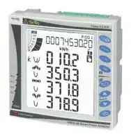
## **Front anel descri tion p p**
**==> picture [245 x 186] intentionally omitted <==**
**----- Start of picture text -----**<br>
5<br>1<br>4<br>2<br>3<br>**----- End of picture text -----**<br>
## **1. Key-pad**
To program the configuration parameters and scroll the variables on the display.
## **2. Display**
LCD-type with alphanumeric indications to:
- display configuration parameters;
- display all the measured variables.
## **3. kWh LED**
Red LED blinking proportional to the energy being measured
## **4. Alarm LED’s**
Red LED’s light-on when virtual alarms are activated.
## **5. Main bar-graph**
- To display the power consumption versus the installed power.
**17**
Specifications are subject to change without notice WM30 96 DS 161213
**WM30 96**
## **Dimensions and Panel cut-out**
**18**
Specifications are subject to change without notice WM30 96 DS 161213
Updated at June 9, 2026
Founded in Milan in 1931, Carlo Gavazzi is a globally recognized leader in the design and manufacture of high-quality automation components. For nearly a century, the company has driven technological innovation in the industrial and building automation markets. With ISO 9001-certified production facilities across Europe and Asia, Carlo Gavazzi delivers state-of-the-art solutions tailored for demanding applications, including HVAC, renewable energy, semiconductor manufacturing, and electric vehicle charging infrastructure. Our extensive portfolio of Carlo Gavazzi components focuses heavily on their industry-leading switching and sensing technologies. We carry a comprehensive selection of solid state relays, contactors, and power relays engineered for exceptional reliability and thermal performance. Alongside these robust switching solutions, our range features a wide array of precision sensors, with a strong emphasis on proximity switches and light sensors that are critical for automated manufacturing processes, mobile equipment, and access control systems. Beyond core sensing and switching, the Carlo Gavazzi lineup extends into essential power management, circuit protection, and control devices. This includes highly efficient AC/DC converters, thermal magnetic circuit breakers, and advanced panel instrumentation designed to monitor and optimize energy efficiency. From current sensing transformers to motor starters, engineers consistently trust Carlo Gavazzi to provide competitive, dependable, and forward-thinking components for their most complex automation challenges.
About Novapart
Novapart is a B2B electronic component broker specialising in stock shortages and cost reduction. We source hard-to-find parts and identify compliant alternatives across a catalogue of 540,000+ components from 500+ manufacturers.
Learn more →Stock Shortage Specialist
When a component is unavailable, discontinued or has an unacceptable lead time, we tap into our network of vetted European and Asian distributors to source what you need — without compromising on quality or traceability.
Request a quote →Compliant Alternatives
We identify pin-to-pin, electrically equivalent substitutes that meet the same certifications (RoHS, AEC-Q100, REACH) as your original specification — validated against datasheets, not just part numbers. Often at a lower cost.
BOM Analysis service →