


WLF12PXRGB2000SQP.
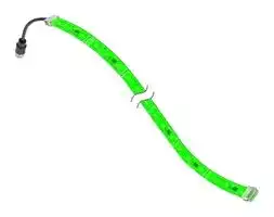
STRIP LIGHT, BLUE/GREEN/RED, 30VDC
- Manufacturer: BANNER ENGINEERING
- Product type: Visual Signal Indicator Units
- Module Lens Colour:Blue, Green, Red; Supply Voltage VAC:-; Supply Voltage VDC:30V; Visual Signal Type:Flashing; Lens Diameter:-; Product Range:WLF12 Pro Series; IP 86AK0660
- SVHC: No SVHC (15-Jan-2018)
- Power Rating: -
- Lens Diameter: -
- Product Range: WLF12 Pro Series
- External Height: 79.72"
- IP / NEMA Rating: IP66, IP67, IP69K
- Module Lens Colour: Blue, Green, Red
- Supply Voltage VAC: -
- Supply Voltage VDC: 30V
- Visual Signal Type: Flashing
- Operating Temperature Max: 45°C
- Operating Temperature Min: -20°C
| Delivery and price | |
|---|---|
| Units per pack | 1 |
| Price | 252.68 € |
| Current stock | 10+ |
| Lead time | 30 days |
## WLF12 Pro Flexible LED Strip Light Instruction Manual

**==> picture [464 x 368] intentionally omitted <==**

Original Instructions p/n: 234631 Rev. A October 17, 2023 © Banner Engineering Corp. All rights reserved.

**==> picture [57 x 57] intentionally omitted <==**

## Contents

**Chapter 1 Features** Pro Editor......................................................................................................................................................................................................  3 Models ..........................................................................................................................................................................................................  4 **Chapter 2 Wiring.....................................................................................................................  5 Chapter 3 Cutting Instructions..............................................................................................  7 Chapter 4 Mounting Instructions..........................................................................................  9 Chapter 5 Specifications** FCC Part 15 Class A ..................................................................................................................................................................................  12 Industry Canada ICES-003(A)....................................................................................................................................................................  13 Dimensions.................................................................................................................................................................................................  13 **Chapter 6 Accessories** LC25 Pro Controllers..................................................................................................................................................................................  15 Mounting Accessories.................................................................................................................................................................................  15 Cordsets .....................................................................................................................................................................................................  16 Splitter Cordsets .........................................................................................................................................................................................  17 **Chapter 7 Banner Engineering Corp Limited Warranty....................................................  19**

2

WLF12 Pro Flexible LED Strip Light Instruction Manual

Chapter Contents Pro Editor ............................................................................................................................................................................................................  3 Models.................................................................................................................................................................................................................  4

## Chapter 1

## Features

Banner’s WLF12 Pro Flexible LED Strip Light has been engineered to integrate easily into a broad range of industrial applications and environments. Its rugged yet flexible housing can be cut to length, allowing users to customize the light to their ideal shape. The light installs easily with integral high-strength adhesive tape, for creative use on an AGV, machine, or assembly station. The programmable RGB LEDs offer proven durability, a wide range of colors, and animations to fit any indication needs.

- Industrial light with RGB LEDs that provides flexible and bright status indication

- Programmable using Banner's LC25 Pro Controller and controllable using the LC25 Pro Controller with IO-Link

- Pro Editor software configuration and LC25 Pro Controller gives access to color, flashing, intensity, and animation settings, as well as advanced operating modes for displaying distance, count, time, and position

- All models have an M12 connector for plug-and-play indication

- Low-profile, space-saving design

- Rugged, water-resistant design, suitable for damp location use

- Available in five lengths from 300 mm to 2000 mm

- Very high-bonding strength tape pre-applied to the back of the light to mount the WLF12 without mounting brackets

- Optional brackets are available for an even more secure installation and positioning

- Both straight and curved installation possible

To connect the light to Banner's Pro Editor Software, use with the LC25C-WLF12-RGB7Q controller. To connect the light to an IO-Link master, use with the LC25C-WLF12-KQ controller. For more ae information, refer to the LC25 Pro Controller datasheet, p/n 234627.

IMPORTANT: Read the following instructions before operating the light. Please download the complete WLF12 Pro Flexible LED Strip Light technical documentation, available in multiple languages, from www.bannerengineering.com for details on the proper use, applications, Warnings, and installation instructions of this device.

## Pro Editor

**==> picture [185 x 80] intentionally omitted <==**

**----- Start of picture text -----**<br>
hy ae<br>**----- End of picture text -----**<br>


Use Banner's Pro Editor software and Pro Converter Cable to create custom configurations by selecting different colors, flash patterns, and animations.

For more information visit www.bannerengineering.com/proeditor.

IMPORTANT: The WLF12 needs an LC25CWLF12-RGB7Q to connect to the Pro Editor software.

October 17, 2023

© Banner Engineering Corp. All rights reserved.

3

WLF12 Pro Flexible LED Strip Light Instruction Manual

**==> picture [57 x 57] intentionally omitted <==**

## Models

## Model Key

**==> picture [500 x 107] intentionally omitted <==**

**----- Start of picture text -----**<br>
Family Style Cascade Color Lighted Length (mm) Construction Connector [(1)]<br>WLF12 P X RGB 300 S QP<br>300 = 300 mm<br>600 = 600 mm<br>X = Non- RGB = RGB  S = Sealed  QP = 150 mm (6 in) PVC-jacketed cable<br>WLF12 P = Pro cascadable Multicolor 900 = 900 mm (IP66, IP67, IP69K  with a 4-pin M12 male quick-disconnect<br>per DIN 40050-9) connector<br>1200 = 1200 mm<br>2000 = 2000 mm<br>**----- End of picture text -----**<br>


> (1) Models with a quick-disconnect connector require a mating cordset.

October 17, 2023

© Banner Engineering Corp. All rights reserved.

4

WLF12 Pro Flexible LED Strip Light Instruction Manual

**==> picture [57 x 57] intentionally omitted <==**

## Chapter Contents

## Chapter 2

## Wiring

## WLF12 Wiring

**==> picture [500 x 63] intentionally omitted <==**

**----- Start of picture text -----**<br>
4-pin Male M12 Pinout Pinout Key and Wiring<br>1 1.  Brown - 12 V DC<br>2 2.  White - BI<br>4 3.  Blue - DC Common<br>4.  Black - DI<br>3<br>**----- End of picture text -----**<br>


## LC25C with WLF12 Wiring[(1)]

Pro Controller Wiring

**==> picture [500 x 70] intentionally omitted <==**

**----- Start of picture text -----**<br>
4-pin Male M12 Pinout Pinout Key and Wiring  [(2)]<br>1 1.  Brown - Input 1: 12 V DC to 30 V DC<br>2 2.  White - Input 3: 12 V DC to 30 V DC<br>3.  Blue - DC Common<br>4 4.  Black - Input 2: 12 V DC to 30 V DC<br>3<br>**----- End of picture text -----**<br>


Pro Controller with IO-Link Wiring

**==> picture [500 x 70] intentionally omitted <==**

**----- Start of picture text -----**<br>
4-pin Male M12 Pinout Pinout Key and Wiring<br>1 1.  Brown - 18 V DC to 30 V DC<br>2.  White - Not used<br>2<br>3.  Blue - DC Common<br>4 4.  Black - IO-Link Communication<br>3<br>**----- End of picture text -----**<br>


> (1) Contact the factory for instructions on how to use a WLF12 without an LC25C.

> (2) Input functionality can change depending on the configuration created with Pro Editor. Refer to wiring diagrams in the selected mode in Pro Editor.

October 17, 2023

© Banner Engineering Corp. All rights reserved.

5

**==> picture [57 x 57] intentionally omitted <==**

## _Blank page_

6

WLF12 Pro Flexible LED Strip Light Instruction Manual

Chapter Contents

## Chapter 3

## Cutting Instructions

1. Prepare the flexible LED strip light.

2. Cut along one of the cutting lines located between each section of three LEDs.

3. Peel back part of the tape on the back, and trim it off.

4.

   - Cover the cut end of the light with silicone glue.

5. Take the extra supplied silicone end cap, and put it on the end of the light. Press out excess glue.

6.

7.

   - Clean the light of the excess glue.

   - Allow twenty-four hours for the glue to dry.

8. Perform a remote teach operation, if applicable, or set the new number of sections of light through software using the LC25 Pro Controller.

October 17, 2023

© Banner Engineering Corp. All rights reserved.

7

**==> picture [57 x 57] intentionally omitted <==**

## _Blank page_

8

WLF12 Pro Flexible LED Strip Light Instruction Manual

**==> picture [57 x 57] intentionally omitted <==**

## Chapter Contents

## Chapter 4

## Mounting Instructions

## Before installation: gather all supporting parts and accessories and remove power from the light.

1. Clean the mounting surface. Ensure that the mounting surface and all other mounting installation parts are dry.

**==> picture [261 x 97] intentionally omitted <==**

2. Remove the protective liner from the tape on the back of the light strip.

3. Align the light strip in the desired installation position, and press the light strip firmly onto the mounting surface. After installing the light strip, wait twenty-four hours for the tape to adhere completely to the mounting surface. Do not touch or move the light strip during this time period.

**==> picture [261 x 105] intentionally omitted <==**

4. Connect the light strip to the controller.

5. Connect the controller to the control device.

October 17, 2023

© Banner Engineering Corp. All rights reserved.

9

WLF12 Pro Flexible LED Strip Light Instruction Manual

**==> picture [57 x 57] intentionally omitted <==**

6. Confirm that the installation is fastened, the wiring is correct, and that the waterproof connecting wire for docking is tightened.

7. Apply power to the light and the controller.

October 17, 2023

© Banner Engineering Corp. All rights reserved.

10

WLF12 Pro Flexible LED Strip Light Instruction Manual

**==> picture [57 x 57] intentionally omitted <==**

## Chapter Contents

FCC Part 15 Class A .........................................................................................................................................................................................  12 Industry Canada ICES-003(A)...........................................................................................................................................................................  13 Dimensions........................................................................................................................................................................................................  13

## Chapter 5

## Specifications

## Supply Voltage

Input voltage without a controller: 12 V DC (±10%)

Input voltage with LC25 Pro Controller: 12 V DC to 30 V DC Input voltage with LC25 Pro Controller with IO-Link: 18 V DC to 30 V DC

Use only with a suitable Class 2 power supply (UL) or SELV power supply (CE)

**==> picture [32 x 103] intentionally omitted <==**

NOTICE: The WLF12 is designed to be used with an LC25C and must be no more than 3.05 m (10 ft) apart. Contact the factory for instructions on how to use a WLF12 without an LC25C.

WARNING: The WLF12 will be permanently damaged if a supply voltage of greater than 12 V DC is applied directly to the light.

## Supply Current

**==> picture [221 x 141] intentionally omitted <==**

**----- Start of picture text -----**<br>
WLF12<br>Only<br>Typical  WLF12 + LC25C Typical (A)<br>Light<br>Current<br>Length<br>(A)<br>12 V DC 12 V DC 18 V DC 24 V DC 30 V DC<br>300 mm 0.195 0.225 0.17 0.135 0.115<br>600 mm 0.39 0.42 0.31 0.24 0.2<br>900 mm 0.585 0.615 0.45 0.345 0.285<br>1200 mm 0.78 0.81 0.59 0.45 0.37<br>2000 mm 1.3 1.33 0.965 0.73 0.6<br>**----- End of picture text -----**<br>


## Supply Protection Circuitry

When a WLF12 is paired with an LC25C, it is protected against reverse polarity and transient voltages

See electrical characteristics on product label

## Connections

150 mm (6 in) PVC-jacketed cable with a 4-pin M12 male quick-disconnect connector

Models with a quick-disconnect require a mating cordset

Do not spray cable with high-pressure sprayer or cable damage will result.

## Operating Temperature

–20 °C to +45 °C (–4 °F to +113 °F)

## Storage Temperature

–35 °C to +70 °C (–31 °F to +158 °F)

## Environmental Rating

Rated IP66, IP67, IP69K per DIN 40050-9

Suitable for damp locations per UL 2108

Do not spray cable with a high-pressure sprayer or cable damage will result.

## Vibration and Mechanical Shock

Vibration: 10 Hz to 55 Hz, 1.0 mm peak-to-peak amplitude per IEC 60068-2-6

Shock: 15G 11 ms duration, half sine wave per IEC 60068-2-27

## Construction

Clear silicone outer housing and end caps

Internally silicone-encapsulated LEDs

Very high-bonding strength tape and protective liner preapplied to the back of the light

## Application Notes

When cutting the WLF12, it is important to use the extra end cap supplied along with silicone glue. See "Cutting Instructions" on page 7

Multiple WLF12s can be connected with a splitter cable to a single LC25C. Note that each WLF12 displays the same color and animation settings. Do not connect more than 2000 mm (78.74 in) in total length to an LC25C.

For indoor or outdoor use, if exposure to direct sunlight is avoided.

## Minimum Bend Radius

15 mm

## Required Overcurrent Protection

**==> picture [32 x 42] intentionally omitted <==**

WARNING: Electrical connections must be made by qualified personnel in accordance with local and national electrical codes and regulations.

Overcurrent protection is required to be provided by end product application per the supplied table.

Overcurrent protection may be provided with external fusing or via Current Limiting, Class 2 Power Supply.

Supply wiring leads < 24 AWG shall not be spliced.

For additional product support, go

to www.bannerengineering.com.

**==> picture [222 x 79] intentionally omitted <==**

**----- Start of picture text -----**<br>
Supply  Supply<br>Required Overcurrent  Required Overcurrent<br>Wiring  Wiring<br>Protection (A) Protection (A)<br>(AWG) (AWG)<br>20 5.0 26 1.0<br>22 3.0 28 0.8<br>24 1.0 30 0.5<br>**----- End of picture text -----**<br>


October 17, 2023

© Banner Engineering Corp. All rights reserved.

11

WLF12 Pro Flexible LED Strip Light Instruction Manual

**==> picture [57 x 57] intentionally omitted <==**

## Mounting

Use pre-applied, very high-bonding strength tape to mount the WLF12 without mounting brackets, see "Mounting Instructions" on page 9

If needed, use mounting bracket LMBWLF12C, see "Mounting Accessories" on page 15

**==> picture [167 x 42] intentionally omitted <==**

**----- Start of picture text -----**<br>
Certifications<br>Banner Engineering BV<br>Park Lane, Culliganlaan 2F bus 3<br>1831 Diegem, BELGIUM<br>**----- End of picture text -----**<br>


**==> picture [137 x 54] intentionally omitted <==**

## Light Characteristics

Sections of three LEDs can be individually controlled at a time LED Pitch: 16.67 mm

Beam Angle: 120°

RGB LED PWM Frequency: 2 kHz

**==> picture [483 x 386] intentionally omitted <==**

**----- Start of picture text -----**<br>
Dominant  Color Coordinates [(1)] Lumens at Specified Length (Typical at 25 °C)<br>Wavelength<br>Color  (nm) or Color<br>Temperature  X  Y  300 mm  600 mm  900 mm  1200 mm  2000 mm<br>(CCT)<br>Daylight White 5000K 0.345 0.352 85 170 255 340 565<br>Incandescent<br>2700K 0.46 0.411 70 140 210 280 465<br>White<br>Warm White 3000K 0.44 0.404 75 150 225 300 500<br>Fluorescent<br>4100K 0.376 0.374 90 180 270 360 600<br>Light<br>Neutral White 5700K 0.328 0.337 85 170 255 340 565<br>Cool White 6500K 0.314 0.324 85 170 255 340 565<br>Green 520 0.144 0.703 55 110 165 220 365<br>Red 618 0.686 0.312 30 60 90 120 200<br>Yellow 575 0.45 0.482 80 160 240 320 530<br>Blue 464 0.142 0.044 10 20 30 40 65<br>Magenta - 0.363 0.162 35 70 105 140 230<br>Cyan 494 0.143 0.365 60 120 180 240 400<br>Amber 590 0.543 0.415 55 110 165 220 365<br>Rose - 0.529 0.234 30 60 90 120 200<br>Lime Green 561 0.367 0.542 75 150 225 300 500<br>Orange 603 0.62 0.36 40 80 120 160 265<br>Sky Blue 487 0.143 0.26 65 130 195 260 430<br>Violet - 0.18 0.076 20 40 60 80 130<br>Spring Green 509 0.144 0.66 60 120 180 240 400<br>**----- End of picture text -----**<br>


## FCC Part 15 Class A

This equipment has been tested and found to comply with the limits for a Class A digital device, pursuant to part 15 of the FCC Rules. These limits are designed to provide reasonable protection against harmful interference when the equipment is

(1) Refer to the CIE 1931 (x,y) Chromaticity Diagram to show equivalent color with indicated color coordinates. Actual coordinates may differ ± 5%.

October 17, 2023

© Banner Engineering Corp. All rights reserved.

12

WLF12 Pro Flexible LED Strip Light Instruction Manual

**==> picture [57 x 57] intentionally omitted <==**

operated in a commercial environment. This equipment generates, uses, and can radiate radio frequency energy and, if not installed and used in accordance with the instruction manual, may cause harmful interference to radio communications. Operation of this equipment in a residential area is likely to cause harmful interference in which case the user will be required to correct the interference at his own expense.

## Industry Canada ICES-003(A)

This device complies with CAN ICES-3 (A)/NMB-3(A). Operation is subject to the following two conditions: 1) This device may not cause harmful interference; and 2) This device must accept any interference received, including interference that may cause undesired operation.

Cet appareil est conforme à la norme NMB-3(A). Le fonctionnement est soumis aux deux conditions suivantes : (1) ce dispositif ne peut pas occasionner d'interférences, et (2) il doit tolérer toute interférence, y compris celles susceptibles de provoquer un fonctionnement non souhaité du dispositif.

## Dimensions

**==> picture [400 x 124] intentionally omitted <==**

**----- Start of picture text -----**<br>
44 171 12.8<br>14.8<br>L1<br>L2<br>M12 x 1.0 44<br>6.4<br>xxxxxxxxxxxxxxxxxxxxxx TAPE<br>**----- End of picture text -----**<br>


Models L1 L2 WLF12..300.. 300 mm (11.81 in) 325 mm (12.8 in) WLF12..600.. 600 mm (23.6 in) 625 mm (24.61 in) WLF12..900.. 900 mm (35.43 in) 925 mm (36.42 in) WLF12..1200.. 1200 mm (47.24 in) 1225 mm (48.23 in) WLF12..2000.. 2000 mm (78.74 in) 2025 mm (79.72 in)

October 17, 2023

© Banner Engineering Corp. All rights reserved.

13

**==> picture [57 x 57] intentionally omitted <==**

## _Blank page_

14

WLF12 Pro Flexible LED Strip Light Instruction Manual

**==> picture [57 x 57] intentionally omitted <==**

## Chapter Contents

LC25 Pro Controllers.........................................................................................................................................................................................  15 Mounting Accessories .......................................................................................................................................................................................  15 Cordsets ............................................................................................................................................................................................................  16 Splitter Cordsets................................................................................................................................................................................................  17

## Chapter 6

## Accessories

## LC25 Pro Controllers

## LC25C-WLF12-RGB7Q

- In-line LC25 Pro Controller with M12 connectors

- Pro Editor software configuration and three discrete inputs gives access to color, flashing, intensity, and animation settings, as well as advanced operating modes for displaying distance, count, time and position

## LC25C-WLF12-KQ

- In-line LC25 Pro Controller with IO-Link and M12 connectors

- IO-Link gives full access to LED control, color, flashing, intensity, and animation settings, as well as advanced level, gauge, and segment operating modes

## Mounting Accessories

## LMBWLF12C

- Set of 10 clamp brackets

- • Translucent silicone • Designed for M3 or No. 4 mounting hardware

**==> picture [102 x 54] intentionally omitted <==**

**----- Start of picture text -----**<br>
6<br>2X Ø2<br>5.5<br>27<br>**----- End of picture text -----**<br>


October 17, 2023

© Banner Engineering Corp. All rights reserved.

15

WLF12 Pro Flexible LED Strip Light Instruction Manual

**==> picture [57 x 57] intentionally omitted <==**

## Cordsets

**==> picture [500 x 517] intentionally omitted <==**

**----- Start of picture text -----**<br>
4-Pin Threaded M12 Cordsets—Single Ended<br>Model  Length  Style  Dimensions  Pinout (Female)<br>MQDC-403 1 m (3.28 ft)<br>44 Typ.<br>MQDC-406 2 m (6.56 ft)<br>2<br>1<br>M12 x 1<br>Straight  ø 14.5 3<br>MQDC-410 3 m (9.8 ft)  Ø5.2 mm 4 5<br>7 mm<br>58 mm<br>1 = Brown<br>2 = White<br>32 Typ. 3 = Blue<br>[1.26"] 4 = Black<br>5 = Unused<br>2<br>30 Typ. 3<br>[1.18"]<br>1<br>MQDC-406RA 2 m (6.56 ft)  Right-Angle  4<br>M12 x 1<br>ø 14.5 [0.57"]<br>Ø5.2 mm<br>7 mm<br>58 mm<br>4-Pin Threaded M12 Cordsets—Double Ended<br>Model  Length  Style  Dimensions  Pinout<br>MQDEC-401SS  0.31 m (1 ft)   Female<br>MQDEC-402SS 0.6 m (1.97 ft)<br>2<br>MQDEC-403SS 0.91 m (2.99 ft)  40 Typ. 1<br>[1.58"]<br>3<br>MQDEC-406SS  1.83 m (6 ft)  4<br>M12 x 1<br>Male Straight/ ø 14.5 [0.57"] Male<br>Female Straight  44 Typ.<br>[1.73"] 1<br>2<br>MQDEC-410SS  3 m (9.4 ft)  4<br>M12 x 1 3<br>ø 14.5 [0.57"]<br>1 = Brown<br>2 = White<br>3 = Blue<br>4 = Black<br>**----- End of picture text -----**<br>


October 17, 2023

© Banner Engineering Corp. All rights reserved.

16

WLF12 Pro Flexible LED Strip Light Instruction Manual

## Splitter Cordsets

**==> picture [471 x 576] intentionally omitted <==**

**----- Start of picture text -----**<br>
4-Pin Threaded M12 Splitter Cordsets—Flat Junction<br>Model  Branches (Female)  Trunk (Male)  Pinout<br>CSB-M1240M1240 No branch  No trunk   Female<br>CSB-M1240M1241 No trunk<br>2 × 0.3 m (1 ft)  2<br>CSB-M1241M1241 0.30 m (1 ft)  1<br>S 3<br>CSB-M1243M12413 2 × 1 m (3.28 ft)  1 m (3.28 ft)  4<br>CSB-M1248M1241 2 × 0.3 m (1 ft)  2.44 m (8 ft)<br>Male<br>94.5 18.0 44 Typ. 1<br>p. (0.18"] 71" [1.73"] 2 lo<br>Ø14.5 [0.57"] 4<br>Ø14.5 [0.57"] in siiee one M12 x 1 | 3 ©)<br>M12 x 1 Woo “ll alJi ur)= 1 = Brown<br>2 = White<br>35 [1.38"]<br>3 = Blue<br>4 = Black<br>4-Pin Threaded M12 Male to 5-Pin Threaded M12 Female Splitter Cordset<br> Model Branches (Female) Wiring<br>1 1<br>TRUNK 2 2<br>(MALE) 3 3 (FEMALE)<br>4 4<br>L1, L2<br>S15YB-M124-M124-0.2M<br>2 × 0.2 m (7.9 in)<br>2<br>3 (FEMALE)<br>mii 4,<br>© -~—ole2|<br>©) oeae S17 I s Mian (+)<br>= 2% ion _wo<br>5-Pin Threaded M12 Splitter Cordset with Flat Junction—Double Ended<br>Model  Trunk (Male)  Branches (Female)  Pinout (Male)  Pinout (Female)<br>1<br>2<br>2 1<br>CSB4-M1251M1250 0.3 m (0.98 ft)  Four (no cable)  Se 4 CN 3<br>AS,<br>3 5 4 5<br>Continued on page 18<br>**----- End of picture text -----**<br>


October 17, 2023

© Banner Engineering Corp. All rights reserved.

17

WLF12 Pro Flexible LED Strip Light Instruction Manual

**==> picture [57 x 57] intentionally omitted <==**

**==> picture [500 x 126] intentionally omitted <==**

**----- Start of picture text -----**<br>
Continued from page 17<br>5-Pin Threaded M12 Splitter Cordset with Flat Junction—Double Ended<br>Model  Trunk (Male)  Branches (Female)  Pinout (Male)  Pinout (Female)<br>Branch 1<br>2 x 19 Branch 2<br>72 mm 1 = Brown  4 = Black<br>Branch 3 2 = White<br>3 x 18 3 = Blue  5 = Gray<br>Branch 4<br>32 mm<br>**----- End of picture text -----**<br>


October 17, 2023

© Banner Engineering Corp. All rights reserved.

18

WLF12 Pro Flexible LED Strip Light Instruction Manual

**==> picture [57 x 57] intentionally omitted <==**

Chapter Contents

## Chapter 7 Banner Engineering Corp Limited Warranty

Banner Engineering Corp. warrants its products to be free from defects in material and workmanship for one year following the date of shipment. Banner Engineering Corp. will repair or replace, free of charge, any product of its manufacture which, at the time it is returned to the factory, is found to have been defective during the warranty period. This warranty does not cover damage or liability for misuse, abuse, or the improper application or installation of the Banner product.

THIS LIMITED WARRANTY IS EXCLUSIVE AND IN LIEU OF ALL OTHER WARRANTIES WHETHER EXPRESS OR IMPLIED (INCLUDING, WITHOUT LIMITATION, ANY WARRANTY OF MERCHANTABILITY OR FITNESS FOR A PARTICULAR PURPOSE), AND WHETHER ARISING UNDER COURSE OF PERFORMANCE, COURSE OF DEALING OR TRADE USAGE.

This Warranty is exclusive and limited to repair or, at the discretion of Banner Engineering Corp., replacement. IN NO EVENT SHALL BANNER ENGINEERING CORP. BE LIABLE TO BUYER OR ANY OTHER PERSON OR ENTITY FOR ANY EXTRA COSTS, EXPENSES, LOSSES, LOSS OF PROFITS, OR ANY INCIDENTAL, CONSEQUENTIAL OR SPECIAL DAMAGES RESULTING FROM ANY PRODUCT DEFECT OR FROM THE USE OR INABILITY TO USE THE PRODUCT, WHETHER ARISING IN CONTRACT OR WARRANTY, STATUTE, TORT, STRICT LIABILITY, NEGLIGENCE, OR OTHERWISE.

Banner Engineering Corp. reserves the right to change, modify or improve the design of the product without assuming any obligations or liabilities relating to any product previously manufactured by Banner Engineering Corp. Any misuse, abuse, or improper application or installation of this product or use of the product for personal protection applications when the product is identified as not intended for such purposes will void the product warranty. Any modifications to this product without prior express approval by Banner Engineering Corp will void the product warranties. All specifications published in this document are subject to change; Banner reserves the right to modify product specifications or update documentation at any time. Specifications and product information in English supersede that which is provided in any other language. For the most recent version of any documentation, refer to: www.bannerengineering.com.

For patent information, see www.bannerengineering.com/patents.

October 17, 2023

© Banner Engineering Corp. All rights reserved.

19

## LinkedIn

Twitter

Facebook

© 2023. All rights reserved. www.bannerengineering.com
Updated at April 23, 2026
Founded in 1966, Banner Engineering is a globally recognized leader in the design and manufacture of industrial automation products. The company is renowned for developing innovative, high-quality solutions that improve operational efficiency, safeguard personnel, and optimize manufacturing processes across a diverse range of industries. Our extensive selection of Banner Engineering components prominently features their industry-leading sensing technologies. We offer a comprehensive array of precision light sensors engineered for accurate detection and measurement in demanding environments. Complementing this core sensing portfolio is a robust offering of automation signaling devices, including visual signal indicator units and essential accessories, which provide clear and immediate communication of machine status. Beyond primary sensing and indication solutions, our range encompasses critical components for broader process control and machine safety. This includes advanced process controllers, reliable pressure sensors and transducers, and dependable safety relays. Supported by a variety of purpose-built sensor accessories and fiber optic lead assemblies, Banner Engineering delivers the durable, high-performance technologies required to build and maintain sophisticated automated systems.
About Novapart
Novapart is a B2B electronic component broker specialising in stock shortages and cost reduction. We source hard-to-find parts and identify compliant alternatives across a catalogue of 410,000+ components from 500+ manufacturers.
Learn more →Stock Shortage Specialist
When a component is unavailable, discontinued or has an unacceptable lead time, we tap into our network of vetted European and Asian distributors to source what you need — without compromising on quality or traceability.
Request a quote →Compliant Alternatives
We identify pin-to-pin, electrically equivalent substitutes that meet the same certifications (RoHS, AEC-Q100, REACH) as your original specification — validated against datasheets, not just part numbers. Often at a lower cost.
BOM Analysis service →