
Image not available
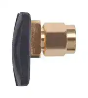
Illustrative purposes only

WCM.01.0111
RF Antenna, 2.5 GHz to 2.4 GHz, 2 dBi, 10 W, 50ohm, Linear, SMA Connector
⚠️ Reference pricing provided. In case of supply shortages, we will connect you with our trusted procurement partners to ensure your project's continuity.
- Manufacturer: TAOGLAS
- Product type:
- Gain: 2dBi
- SVHC: To Be Advised
- VSWR: -
- Input Power: 10W
- Antenna Type: WiFi / Bluetooth
- Frequency Max: 2.5GHz
- Frequency Min: 2.4GHz
- Product Range: -
- Input Impedance: 50ohm
- Antenna Mounting: SMA Connector
- Antenna Polarisation: Linear
| Delivery and price | |
|---|---|
| Units per pack | 250 |
| Price | 4.32 € |
| Current stock | 10+ |
| Lead time | 30 days |
Datasheet

## **Specification**

|Part No.|:|**WCM.01.0111**|
|---|---|---|
|Product Name:|:|2.4GHz Button Antenna|
|Features|:|Tiny Size – 19.8mm*14.3mm*16.4mm|
|||2400MHz to 2500MHz Antenna|
|||Wi-Fi / Bluetooth|
|||>60% Efficiency|
|||Connector: SMA(M)|
|||IP67 Waterproof Housing|
|||Omni directional|
|||ROHS Compliant|


Page 1 of 31

SPE-17-8-090/A/IC

## **1. Introduction**

The WCM.01 2.4GHz antenna is the smallest SMA(M) connector mount external antenna in the market, fitting into spaces no other traditional monopole, dipole or rubber ducky antenna can go. Its unique PIFA design provides omni-directional gain across the 2.4GHz to 2.5GHz range, ensuring constant reception and transmission for 2.4GHz Wi-Fi and Bluetooth applications.

This antenna features greater than 60% efficiency when connected directly to the ground plane of the device.

Typical Applications Include:

- Application Points

- Routers

- IoT M2M Devices

- Smart Home Applications

The WCM.01 antenna has an IP67 water proof enclosure and comes with an SMA(M) connector, making it compatible with most Wi-Fi applications and routers on the market. An RP-SMA(M) version is also available, WCM.01.0151. For ideal radiation, mount the WCM.01 clear of metal.

Many module manufacturers specify peak gain limits for any antennas that are to be connected to that module. Those peak gain limits are based on freespace conditions. In practice, the peak gain of an antenna tested in freespace can degrade by at least 1 or 2 dBi when put inside a device. So ideally you should go for a slightly higher peak gain antenna than mentioned on the module specification to compensate for this effect, giving you better performance.

SPE-17-8-090/A/IC Page 2 of 31

Upon testing of any of our antennas with your device and a selection of appropriate layout, integration technique, or cable, Taoglas can make sure any of our antennas' peak gain will be below the peak gain limits. Taoglas can then issue a specification and/or report for the selected antenna in your device that will clearly show it complying with the peak gain limits, so you can be assured you are meeting regulatory requirements for that module.

For example, a module manufacturer may state that the antenna must have less than 2 dBi peak gain, but you don't need to select an embedded antenna that has a peak gain of less than 2 dBi in freespace. This will give you a less optimized solution. It is better to go for a slightly higher freespace peak gain of 3 dBi or more if available. Once that antenna gets integrated into your device, performance will degrade below this 2 dBi peak gain due to the effects of ground plane, surrounding components, and device housing. If you want to be absolutely sure, contact Taoglas and we will test. Choosing a Taoglas antenna with a higher peak gain than what is specified by the module manufacturer and enlisting our help will ensure you are getting the best performance possible without exceeding the peak gain limits.

Contact your regional Taoglas sales office for more information.

Page 3 of 31

SPE-17-8-090/A/IC

**2. Specification**

|Electrical|Electrical|Electrical|Electrical|Electrical|
|---|---|---|---|---|
|Frequency (MHz)<br>~~a~~||2400<br>~~a~~|2450<br>~~a~~|2500<br>~~a~~|
|**Efficiency (%)**<br>~~a~~<br>~~eee~~|||||
|In free space<br>~~eee~~||33.30<br>~~eee~~|30.36<br>~~eee~~|29.65<br>~~eee~~|
|10X10cm ground plane|center|63.43|71.44|66.85|
||edge|55.85|68.43|61.73|
|20X20cm ground plane|center|64.20|71.40|63.97|
||edge|62.55|81.30|69.73|
|30X30cm ground plane|center|58.31|70.49|60.87|
||edge|62.11|73.46|61.90|
|**Average gain (dBi)**<br>~~LT~~|||||
|In free space||-4.78|-5.18|-5.28|
|10X10cm ground plane|center|-1.98|-1.46|-1.75|
||edge|-2.53|-1.65|-2.10|
|20X20cm ground plane|center|-1.92|-1.46|-1.94|
||edge|-2.04|-0.90|-1.57|
|30X30cm ground plane|center|-2.34|-1.52|-2.16|
||edge|-2.07|-1.34|-2.08|
|**Peak gain (dBi)**<br>~~LT~~|||||
|In free space||0.89|0.40|0.12|
|10X10cm ground plan|center|2.02|2.45|2.37|
||edge|3.46|4.09|3.47|
|20X20cm ground plane|center|4.26|4.54|3.69|
||edge|4.02|5.40|4.65|
|30x30cm ground plane|center|3.64|4.85|4.06|
||edge|3.79|4.23|3.15|
|Return Loss(dB)|<-6||||
|Radiation|Omni-directional||||
|Polarization|Linear||||
|Impedance|50 Ω||||
|Input Power|10W||||


SPE-17-8-090/A/IC Page 4 of 31

Mechanical ~~LT~~ Antenna Dimension 19.8mm*14.3mm*16.4mm Casing ABS Connector SMA(M) Weight 6g Ingress Protection Rating IP67 Environmental ~~LO~~ Operation Temperature -40°C ~ + 85°C Storage Temperature -40°C ~ + 85°C Humidity Non-condensing 65°C 95% RH

SPE-17-8-090/A/IC Page 5 of 31

## **3. Antenna Characteristics**

## **3.1 Testing Setup**

a) In free space

e) 20*20cm ground plane edge

c) 10*10cm ground plane edge

b) 10*10cm ground plane center

**==> picture [232 x 33] intentionally omitted <==**

**----- Start of picture text -----**<br>
g) 30*30cm ground<br>f) 30*30cm ground<br>plane edge<br>plane center<br>**----- End of picture text -----**<br>


d) 20*20cm ground plane center

**Figure.1** Antenna Measurement Setup

Page 6 of 31

SPE-17-8-090/A/IC

## **3.2 Return Loss (In free space)**

**Figure 2.** Return loss of WCM.01 in free space

## **3.3 Return Loss (On the ground plane center)**

**Figure 3.** Return loss of WCM.01 on center of different ground plane sizes

SPE-17-8-090/A/IC Page 7 of 31

## **3.4 Return Loss (On ground plane edge)**

**Figure 4.** Return loss of WCM.01 on edge of different ground plane sizes

## **3.5 Efficiency (Free space)**

**Figure 5.** Efficiency of WCM.01 antenna in free space

SPE-17-8-090/A/IC Page 8 of 31

## **3.6 Efficiency (On ground plane center)**

**Figure 6.** Efficiency of WCM.01 on center of different ground plane sizes

## **3.7 Efficiency (On ground plane edge)**

**Figure 7.** Efficiency of WCM.01 on edge of different ground plane sizes

SPE-17-8-090/A/IC Page 9 of 31

**3.8 Peak Gain (Free space)**

**Figure 8.** Peak gain of WCM.01 antenna in free space

## **3.9 Peak Gain (On ground plane center)**

**Figure 9.** Peak gain of WCM.01 on center of different ground plane sizes

SPE-17-8-090/A/IC Page 10 of 31

## **3.10 Peak Gain (On ground plane edge)**

**Figure 10.** Peak gain of WCM.01 on edge of different ground plane sizes

## **3.11 Average Gain (Free space)**

**Figure 11.** Average gain of WCM.01 in free space

SPE-17-8-090/A/IC Page 11 of 31

## **3.12 Average Gain (On ground plane center)**

**Figure 12.** Average gain of WCM.01 on center of different ground plane sizes

## **3.13 Average Gain (On ground plane edge)**

**Figure 13.** Average gain of WCM.01 on edge of different ground plane sizes

Page 12 of 31

SPE-17-8-090/A/IC

## **4. Antenna Radiation Patterns**

The antenna radiation patterns were measured in CTIA certified ETS Anechoic Chamber. The measurement setup as below,

**==> picture [72 x 81] intentionally omitted <==**

**----- Start of picture text -----**<br>
Y<br>X<br>Z<br>**----- End of picture text -----**<br>


Free space

**==> picture [412 x 150] intentionally omitted <==**

**----- Start of picture text -----**<br>
Y<br>Y<br>X<br>X<br>Z  Z<br>we +—<br>On 10X10cm ground plane center  On 10X10cm ground plane edge<br>**----- End of picture text -----**<br>


On 10X10cm ground plane edge

SPE-17-8-090/A/IC Page 13 of 31

**==> picture [329 x 76] intentionally omitted <==**

**----- Start of picture text -----**<br>
Y  Y<br>X<br>X<br>Z<br>Z<br>**----- End of picture text -----**<br>


On 20X20cm ground plane (Center)

On 20X20cm ground plane (Edge)

**==> picture [364 x 159] intentionally omitted <==**

**----- Start of picture text -----**<br>
Y  Y<br>X  X<br>Z  Z<br>On 30X30cm ground plane (Edge)<br>**----- End of picture text -----**<br>


On 30X30cm ground plane (Center)

**Figure.14.** Testing Setup in ETS Anechoic Chamber

Page 14 of 31

SPE-17-8-090/A/IC

## **4.1 2D Radiation Pattern (free space)** XY Plane

**==> picture [275 x 516] intentionally omitted <==**

**----- Start of picture text -----**<br>
X<br>0<br>5<br>330 30<br>300 60<br>270 90 Y<br>240 120<br>210 150<br>180 wien<br>XZ Plane<br>Z<br>0<br>5<br>330 30<br>5<br><——_<br>300 \ 60<br>270 90 X<br>240 420<br>210 150<br>180 (dBi)<br>YZ Plane<br>Z<br>0<br>5<br>330 30<br>5<br>— =<br>—a  |_wa<br>300 “4 \\ 60<br>i,<br>270 90 Y<br>**----- End of picture text -----**<br>


Page 15 of 31

SPE-17-8-090/A/IC

**4.2 3D Radiation Pattern (free space)**

**==> picture [51 x 9] intentionally omitted <==**

**----- Start of picture text -----**<br>
2400MHz<br>**----- End of picture text -----**<br>


**==> picture [51 x 8] intentionally omitted <==**

**----- Start of picture text -----**<br>
2450MHz<br>**----- End of picture text -----**<br>


**==> picture [51 x 8] intentionally omitted <==**

**----- Start of picture text -----**<br>
2500MHz<br>**----- End of picture text -----**<br>


SPE-17-8-090/A/IC Page 16 of 31

**4.3 2D Radiation Pattern (On 10X10cm ground plane center)**

**==> picture [261 x 552] intentionally omitted <==**

**----- Start of picture text -----**<br>
XY Plane<br>X<br>0<br>_——<br>330 30<br>-15.<br>300 60<br>-25——~<br>270| | 1 fas \—} 90<br>Y<br>ial ia<br>240 120<br>a a eS 190<br>180 (dBi)<br>XZ Plane<br>Z<br>0<br>5 ,<br>330 \ 30<br>be 5 | /<br>Ra ,<br>-15 }<br>300 60<br>| $ :<br>270 45= ¢<br>X<br>}_|_\<br>240 120<br>|<br>210 150<br>180 (aBi)<br>YZ Plane<br>Z<br>ty)<br>5<br>330 30<br>5<br>300 (if 60<br>270 ( 90 Y<br>**----- End of picture text -----**<br>


SPE-17-8-090/A/IC Page 17 of 31

**4.4 3D Radiation Pattern (On 10X10cm ground plane center)**

2400MHz

2450MHz

2500MHz

SPE-17-8-090/A/IC Page 18 of 31

**4.5 2D Radiation Pattern (On 10X10cm ground plane edge)**

**==> picture [259 x 563] intentionally omitted <==**

**----- Start of picture text -----**<br>
XY Plane<br>X<br>0<br>a<br>330 30<br>5<br>_<br>300 60<br>Y<br>270 | \ 90<br>N<br>240 120<br>210 150<br>180 nes<br>XZ Plane<br>Z<br>0<br>5<br>330 30<br>300 S 60<br>270 90<br>X<br>240 a 120<br>— ,<br>210 150<br>180 (Bi)<br>YZ Plane  Z<br>0<br>5<br>330 30<br>fo =<br>300 60<br>)<br>270 -— ‘ 90 Y<br>**----- End of picture text -----**<br>


SPE-17-8-090/A/IC Page 19 of 31

**4.6 3D Radiation Pattern (On 10X10cm ground plane edge)**

2400MHz

2450MHz

2500MHz

Page 20 of 31

SPE-17-8-090/A/IC

- **4.7 2D Radiation Pattern (On 20X20cm ground plane center)** XY Plane

**==> picture [239 x 538] intentionally omitted <==**

**----- Start of picture text -----**<br>
X<br>0<br>330 = : 30<br>oo<br>300 60<br>25<br>270 | 145 }—| | 90 Y<br>ly<br>240 [ \ 120<br>210 150 Ba<br>180 (dBi)<br>XZ Plane<br>Z<br>0<br>330 5 T 30<br>270;Ler4 X<br>ome<br>240 120<br>Ne<br>210 150<br>180 (dBi)<br>YZ Plane  Z<br>0<br>5<br>330 30<br>300 i |] 60<br>270 j 90 Y<br>**----- End of picture text -----**<br>


SPE-17-8-090/A/IC Page 21 of 31

## **4.8 3D Radiation Pattern (On 20X20cm ground plane center)**

## 2400MHz

## 2450MHz

2500MHz

SPE-17-8-090/A/IC Page 22 of 31

**4.9 2D Radiation Pattern (On 20X20cm ground plane edge)** XY Plane

**==> picture [223 x 510] intentionally omitted <==**

**----- Start of picture text -----**<br>
X<br>0<br>330 30<br>=<br>300 60<br>270 90<br>=<br>240 120<br>om 1 ae<br>180 (ce<br>XZ Plane<br>Z<br>0<br>5<br>330 30<br>300 60<br>270 \ 90<br>240 \: ff 120<br>210 150 wom<br>180 (aBi)<br>YZ Plane  Z<br>0<br>5<br>330 \ 30<br>y<br>300 \ 60<br>**----- End of picture text -----**<br>


Page 23 of 31

SPE-17-8-090/A/IC

## **4.10 3D Radiation Pattern (On 20X20cm ground plane edge)**

2400MHz

**==> picture [51 x 8] intentionally omitted <==**

**----- Start of picture text -----**<br>
2450MHz<br>**----- End of picture text -----**<br>


2500MHz

Page 24 of 31

SPE-17-8-090/A/IC

## **4.11 2D Radiation Pattern (On 30X30cm ground plane center)**

**==> picture [241 x 533] intentionally omitted <==**

**----- Start of picture text -----**<br>
XY Plane<br>X<br>()<br>330 30<br>300 60<br>\<br>270 | 90 Y<br>240 120<br>210<br>p | i 150<br>a0 (dBi)<br>XZ Plane<br>Z<br>0<br>330 5 +| 30<br>5 |<br>=<br>300 60<br>270 9 X<br>==<br>240 120<br>210 | 150 =e<br>180 (dBi)<br>YZ Plane  Z<br>0<br>5<br>330 30<br>5<br>a<br>300 60<br>270 90<br>**----- End of picture text -----**<br>


SPE-17-8-090/A/IC Page 25 of 31

**4.12 3D Radiation Pattern (On 30X30cm ground plane center)**

2400MHz

2450MHz

2500MHz

Page 26 of 31

SPE-17-8-090/A/IC

**4.13 2D Radiation Pattern (On 30X30cm ground plane edge)**

**==> picture [255 x 535] intentionally omitted <==**

**----- Start of picture text -----**<br>
XY Plane   X<br>0<br>5<br>330 30<br>300 60<br>-25—-<br>270 45 1 } 90 Y<br>\ 4 / q |<br>240 / \ 120<br>f<br>210 150<br>180 (aBi)<br>XZ Plane<br>Z<br>0<br>5<br>330 30<br>—_<br>300 15| 60<br>-25 |<br>j +35, | : X<br>270 145 iN 90<br>|<br>240 | 4 120<br>| J<br>210 150<br>180 (aBi)<br>YZ Plane  Z<br>ty)<br>5<br>330 30<br><—Z<br>300 60<br>270 90 Y<br>**----- End of picture text -----**<br>


SPE-17-8-090/A/IC Page 27 of 31

**4.14 3D Radiation Pattern (On 30X30cm ground plane edge)**

2400MHz

2450MHz

2500MHz

SPE-17-8-090/A/IC Page 28 of 31

## **5. Mechanical Drawing (unit: mm)**

SPE-17-8-090/A/IC Page 29 of 31

## **6. Packaging**

Page 30 of 31

SPE-17-8-090/A/IC

Taoglas makes no warranties based on the accuracy or completeness of the contents of this document and reserves the right to make changes to specifications and product descriptions at any time without notice.

Taoglas reserves the rights to this document and the information contained herein. Reproduction, use or disclosure to third parties without express permission is strictly prohibited.

Copyright © Taoglas Ltd.

SPE-17-8-090/A/IC Page 31 of 31
Updated at June 9, 2026
About Novapart
Novapart is a B2B electronic component broker specialising in stock shortages and cost reduction. We source hard-to-find parts and identify compliant alternatives across a catalogue of 410,000+ components from 500+ manufacturers.
Learn more →Stock Shortage Specialist
When a component is unavailable, discontinued or has an unacceptable lead time, we tap into our network of vetted European and Asian distributors to source what you need — without compromising on quality or traceability.
Request a quote →Compliant Alternatives
We identify pin-to-pin, electrically equivalent substitutes that meet the same certifications (RoHS, AEC-Q100, REACH) as your original specification — validated against datasheets, not just part numbers. Often at a lower cost.
BOM Analysis service →