
Image not available
Illustrative purposes only

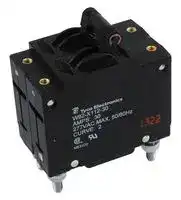
W92-X112-30
CIRCUIT BREAKER, HYDROMAGNETIC, 2P, 277V, 30A
⚠️ Reference pricing provided. In case of supply shortages, we will connect you with our trusted procurement partners to ensure your project's continuity.
- Manufacturer: TE CONNECTIVITY - POTTER&BRUMFIELD
- Product type: Magnetic Hydraulic Circuit Breakers
- Product Range:W9 Series; Current Rating:30A; No. of Poles:2 Pole; Input Voltage VAC:277V; Interrupting Capacity:5kA; Trip Time:20s; Dielectric Strength:1 17M3392
- Trip Time: 20s
- No. of Poles: 2 Pole
- Product Range: W9 Series
- Current Rating: 30A
- Input Voltage VAC: 277V
- Dielectric Strength: 1.5kV
- Interrupting Capacity: 5kA
| Delivery and price | |
|---|---|
| Units per pack | 25 |
| Price | 144.85 € |
| Current stock | 50+ |
| Lead time | 30 days |
Datasheet

° Tyco Catalog 1308242 Issued 3-03 (PDF Rev. 03-10) ~~Pe~~

## W6/W9 series

## **Magnetic Hydraulic P&B Circuit Breakers**

## **Features**

- Designed for the international market.  UL Recognized (UL1077 and UL1500), CSA Accepted and VDE approved.

- Ratings to 50 amps.

- Heavy duty #10-32 stud connections. (W9)

- Quick-connect or screw terminals. (W6)

- Optional 10 amp auxiliary switch.

- Several delay curve options.

- Choice of toggle or rocker actuator per pole or per unit (W6).

- Optional relay/remote trip pole available.

- Trip-free operation.

## **Agency Approvals**

- **UL:** Recognized as Supplementary Protector under UL 1077.  Available models meet Ignition Protection requirements in accordance with UL1500. File E69543.

- **CSA:** Accepted as a Supplementary Protector. File LR15734.

- **VDE:** Approved to VDE 0642/EN 60 934 (Circuit Breakers for Equipment) License No. 73782.

Users should thoroughly review the technical data before selecting a product part number. It is recommended that users also seek out the pertinent approvals files of the agencies/laboratories and review them to confirm the product meets the requirements for a given application.

## **Electrical Data**

**Auxiliary Switch:** See Auxiliary Switch Ratings Table 2 for details. **Calibration:** Breakers will hold 100% of rated current. Breakers may trip between 101% and 124% of rated load (134% for AC/DC units).

Breakers must trip at 125% of rated load and above (135% for AC/DC units).

**Dielectric Strength:** 50/60 Hz., 1500V: DC, 1100V.

**Insulation Resistance:** 100 Megohms at 500VDC.

**Endurance:** 10,000 on/off cycles - 6000 at rated load, 4000 at no load. Units tested at six cycles per minute, 1 second on and 9 seconds off at 25°C ambient.

**Relay Trip Coil:** (Ratings applicable to all W6 models with this option) 24 to 277VAC, 150mA minimum available current; 6 to 48VDC, 300mA minimum available current.

## **Typical Resistance and Impedance**

|**Current**<br>**(Amps)**|**DC**<br>**Resistance**<br>**(Ohms)**|**50/60 Hz.**<br>**Impedance**<br>**(Ohms)**|
|---|---|---|
|0.2<br>1.0<br>2.0<br>5.0<br>10.0<br>20.0<br>30.0<br>40.0<br>50.0|90<br>1.2<br>0.28<br>0.04<br>0.013<br>0.004<br>0.0027<br>0.002<br>0.0015|90<br>1.2<br>0.28<br>0.04<br>0.013<br>0.005<br>0.004<br>0.002<br>0.0015|


Tolerance:  0.1 - 4.99 ± 15%; 5 - 9.99 ± 20%; 10 - 15 ± 25%; 16 - 30 ± 50%.

## **Mechanical/Environmental Data**

**Operating Temperature:** -40°C to +85°C.

**Humidity:** Meets requirements of Mil-STD-202 method 103. **Shock:** Tested per Mil-STD-202, method 213, test condition C (100g @ 6 ms).

**Vibration:** Tested per Mil-STD-202, method 201, 10-55 Hz., 0.06" (1.52mm) total excursion in 2 planes.

**Fungus And Moisture Resistance:** Special moisture resistant finish applied to all ferrous parts. Plastic parts are made of inherently fungus resistant material.

**Marking:** International “1” and “0” symbols are marked on the toggle for both W6 and W9. W9 units have “ON” and “OFF” molded into the area at the base of the toggle. On a special order basis, graphics can be imprinted on the rockers of rocker actuated W6 units. VDE approved versions of rocker actuated W6 breakers have their rockers imprinted with “1” and “0.”

**Mounting:** Units are mounted with two #6-32 screws from the front of the panel.  Metric models for use with M3 x 0.5 screws are available.  To maintain published performance specifications, units should not be mounted more than 90° from their normal upright position.

**Weight:** Approximately 2.5 ounces per pole.

## **Approvals and Ratings Table 1**

**W6 Series UL1077/CSA (All Circuit Functions)**

|**Maximum**<br>**Voltage**|**Frequency**<br>**(Hz)**|**Phase**|**Current**<br>**Rating**<br>**(Amps)**|**Interrupting**<br>**Capacity**<br>**(Amps)**|
|---|---|---|---|---|
|65<br>277<br>277<br>277/480|DC<br>50/60<br>50/60<br>50/60|-<br>1<br>1<br>3Ø-Wye|0.2 - 50<br>0.2 - 20<br>21 - 50<br>0.2 - 20|2,000<br>5,000<br>2,500<br>5,000|


**W9 Series UL1077/CSA (All Circuit Functions)**

|**Maximum**<br>**Voltage**|**Frequency**<br>**(Hz)**|**Phase**|**Current**<br>**Rating**<br>**(Amps)**|**Interrupting**<br>**Capacity**<br>**(Amps)**|
|---|---|---|---|---|
|65<br>277<br>277/480|DC<br>50/60<br>50/60|-<br>1<br>3Ø-Wye|0.2 - 50<br>0.2 - 50<br>0.2 - 20|2,000<br>5,000<br>5,000|


|**Maximum**<br>**Voltage**|**Frequency**<br>**(Hz)**|**Phase**|**Current**<br>**Rating**<br>**(Amps)**|**Interrupting**<br>**Capacity**<br>**(Amps)**|
|---|---|---|---|---|
|65<br>250<br>250<br>415/240|DC<br>50/60<br>50/60<br>50/60|-<br>1<br>1<br>3Ø|0.2-50<br>0.2-30<br>31-50<br>0.2-30|2,000<br>5,000<br>2,000<br>5,000|


## **W6 or W9 Series UL1500 (Circuit Function X)**

|**Maximum**<br>**Voltage**|**Frequency**<br>**(Hz)**|**Phase**|**Current**<br>**Rating**<br>**(Amps)**|**Interrupting**<br>**Capacity**<br>**(Amps)**|
|---|---|---|---|---|
|48<br>125/250<br>250|DC<br>50/60<br>50/60|-<br>1<br>3Ø-Wye|0.2 - 50<br>0.2 - 50<br>0.2 - 50|3,000<br>1,000<br>1,000|


## **Auxiliary Switch Ratings Table 2**

## **UL/CSA**

|**Switch**||**Voltage**|**Current**|**Terminals**|**Terminals**||
|---|---|---|---|---|---|---|
|**Number**||**50/60 Hz.**|**(Amps)**||**WxTxL**||
|A||125|10|.093 x .020 x .250|||
|||||(2.36 x .51 x 6.40)|(2.36 x .51 x 6.40)||
||||||||
|Revised 03-10||Dimensions are in inches over|||Dimensions are shown for reference||
|www.tycoelectronics.com||(millimeters) unless otherwise<br>specified.|||purposes only. Specifications and<br>availability subject to change.||


USA: 1-800-522-6752 South America: 55-11-2103-6000 Canada: 1-905-470-4425 Hong Kong: 852-2735-1628 1 Mexico: 01-800-733-8926 Japan: 81-44-844-8013 C. America: 52-55-1106-0803 UK: 44-8706-080208

Catalog 1308242 Issued 3-03 (PDF Rev. 03-10)

**==> picture [248 x 23] intentionally omitted <==**

**----- Start of picture text -----**<br>
Time vs. Current Trip Curves For W6 Series and W9 Series<br>AC 50/60 Hz.<br>**----- End of picture text -----**<br>


**==> picture [529 x 538] intentionally omitted <==**

**----- Start of picture text -----**<br>
DC & 50/60 Hz.<br>10,0001000400 Hz. hA SS f e CURVE 0 INSTANTANEOUS f;ee OVERLOAD  @ 50/60 Hz. & DC    @ 400 Hz. Po TRIP TIMES 10,0001000 — a= CURVE 2 STANDARD DELAY 50/60 Hz.  —————SS                                 (SEC.)OVERLOAD    TRIP TIMES eee 10,0001000 — |= ee CURVE 3 SHORT DELAY 50/60 Hz.  =| OVERLOAD    TRIP TIMES                                   (SEC.) ee<br>  125%       100 ms max.         May Trip   125%             10 - 150   125%              1 - 15<br>10010 ——esaa Se   150%         55 ms max.  200%         30 ms max.        30 ms max.  400%         15 ms max.  600%         12 ms max. 100 ms max.15 ms max.12 ms max. 10010 eeaaNES co1 a a   800%          .007 - .15  600%            .03 - .75  200%            2.2 - 20  400%              .2 - 2 10010 |aaee|   800%         .003 - .08  600%         .007 - .15  400%           .03 - .25  200%           .15 - 1.5<br>js Oe ee |   800%         12 ms max. 12 ms max. | SS a | 1000%          .005 - .04 | 1000%         .003 - .04<br>1 es 0 1 a 1 NS<br>.1 SSaSSOeI—— SSS .1 SSOeSsISSaeS .1 _——eeSSSS a Sa———SS SS<br>.01 es——— a ee .01 SSSaSs8 ASS SSSa .01 SS 1aSS aSS LOSSCOSSS SSSSSSSSNN<br>.001 S SSS SS SS SS SS SS SS SSS .001 eea ee a .001 Eea |<br>0 100 125   150200   300   400   500   600   700   800   900  1000  1100  1200LOAD CURRENT AS A PERCENT 0 125 100  150200   300   400   500   600   700   800   900  1000  1100  1200LOAD CURRENT AS A PERCENT 0 125 100  150200   300   400   500   600   700   800   900  1000  1100  1200LOAD CURRENT AS A PERCENT<br>OF BREAKER RATING OF BREAKER RATING OF BREAKER RATING<br>MOTOR START / LONG DELAY<br>CURVE 10 HIGH INRUSH 50/60 Hz. AC CURVE 12 HIGH INRUSH 50/60 Hz. CURVE 13 HIGH INRUSH 50/60 Hz.<br>10,0001000 =  —————————— OVERLOAD   TRIP TIMES                               (SEC.)  125%            40 - 500 ee 10,0001000 Pee OVERLOAD    TRIP TIMES                                (SEC.) 10,0001000 | OS 0 a a OVERLOAD    TRIP TIMES                                (SEC.)<br>10010 _—_——aETS a ONIN|=== —————————Os eS eS|eS   200%              9 - 100  400%              2 - 20  600%             .8 - 10  800%             .1 - 4.51000%        .009 - 2 10010 SS_——a=pdeS|ee —————————a a=A ——   125%            10 - 150  200%              3 - 25  400%             .5 - 2.5  600%           .15 - 1  800%         .015 - .7 ee 10010 Se=_—aJoFS|ee —————— Oa6. a a ee ee |   125%              .8 - 30  200%            .15 - 2.5  400%            .03 - .3  600%            .02 - .15  800%          .009 - .12 a<br>_aeSa ee CC| CS a==CN———— 1000%         .009 - .35 A_————————a 1000%          .009 - .09<br>1 a 1 es 1 eS<br>SS SS SS SS NN Sa ee ee ee ee ee ee eee<br>.1 aa ee a .1 eeSSae ee a ee .1 |a<br>.01 poe|a SCRS|GS SN LE .01 aEESS SS NSSeLN SO SO .01 _———aaA8 a ES SS SS aSN a<br>PoiEST Fo: FOCOOSCS~SYstCtC SiS SY SSE _ SS<br>.0010 _— 125 100  150200   300   400   500   600   700   800   900  1000  1100  1200 a LOAD CURRENT AS A PERCENT eeSSee ee a | .0010 ea— 125   150100   200   300   400   500   600   700   800   900  1000  1100  1200 SS LOAD CURRENT AS A PERCENT eeA SS| .0010 a 125   150100   200   300   400   500   600   700   800   900  1000  1100  1200 SC LOAD CURRENT AS A PERCENT<br>OF BREAKER RATING OF BREAKER RATING OF BREAKER RATING<br>DC<br>CURVE 2 STANDARD DELAY DC  CURVE 3 SHORT DELAY DC  CURVE 53 DC HIGH INRUSH<br>10,000 — OVERLOAD    TRIP TIMES 10,000 e e OVERLOAD    TRIP TIMES 10,000 _—— OVERLOAD    TRIP TIMES<br>100010010 SSS_—— eS aeaEN2 Es”e                                 (SEC.)   125%             2 - 55  200%          .60 - 8  400%            .1 - 1.5  600%          .02 - .5  800%        .004 - .05 100010010 _—_——es f SSSaa oa TC~S~s—iCY                               (SEC.)   200%           .16 - 1.5  400%           .03 - .25  600%           .01 - .13  800%         .004 - .05  125%             .6 - 7 100010010 SSS=PN|sea iS|SSDa SS SS                                 (SEC.)   125%           80 - 700  200%           15 - 150  400%             2 - 20  600%          .70 - 10  800%          .10 - 31000%          .01 - .1 eee<br>a | 1000%        .004 - .025 | SS 1000%         .003 - .015 a a SS SO SF<br>1 eS 1 ee 1<br>SSa 8 SS SC| |SS SSSS a SC _——Sea ee ee ee a |<br>.1 Se .1 ss a .1 AOS<br>.01 | .01 a .01 eeee ee ee ce<br>.001 _——a ee ee ee ee ee | .001 eeaee ae a | .001 _——a<br>0 125 100  150200   300   400   500   600   700   800   900  1000  1100  1200LOAD CURRENT AS A PERCENT 0 125   150100  200   300   400   500   600   700   800   900  1000  1100  1200LOAD CURRENT AS A PERCENT 0 125   150100   200   300   400   500   600   700   800   900  1000  1100  1200LOAD CURRENT AS A PERCENT<br>OF BREAKER RATING OF BREAKER RATING OF BREAKER RATING<br>AC/DC<br>CURVE 34 DC, 50/60 Hz. STANDARD DELAY<br>10,000<br>1000 ||ey———————ee OVERLOAD    TRIP TIMES                                (SEC.) ee<br>—   135%              1 - 90<br>10010 |SseSo|a= | eS= ——eSA||   200%           .60 - 20  400%         .095 - 2  600%           .02 - .95  800%         .002 - .451000%         .002 - .09<br>1 a<br>SS  ——<br>a | a SS SL SC<br>.1<br>a<br>.01 SSSA|= — — — =<br>.001 |aa| SSSS<br>0 125   150100   200   300   400   500   600   700   800   900  1000  1100  1200LOAD CURRENT AS A PERCENT<br>135 OF BREAKER RATING<br>TIME IN SECONDS TIME IN SECONDS TIME IN SECONDS<br>TIME IN SECONDS TIME IN SECONDS TIME IN SECONDS<br>TIME IN SECONDS TIME IN SECONDS TIME IN SECONDS<br>TIME IN SECONDS<br>**----- End of picture text -----**<br>


## **Note:**

For instantaneous curves for all voltages refer to Curve 0 Instantaneous under the AC 50/60 Hz. heading.

## **Pulse Tolerance Specifications**

Pulse tolerance is defined as a single pulse of a half sine wave (1/2 cycle or 8 milliseconds) that will not trip the breaker. An inertia wheel for increased pulse tolerance is available by specifying “P” after the time delay curve number in the ordering information. The table at right lists pulse tolerance values of standard and inertia delay models.

**==> picture [207 x 103] intentionally omitted <==**

**----- Start of picture text -----**<br>
Pulse Tolerance Value<br>Time<br>Delay Inertia<br>Voltage Curve Standard Delay<br>2 7.5 18<br>AC 3 6 18<br>50/60 Hz. 10 18 30<br>12 18 30<br>13 18 30<br>To determine pulse tolerance multiply breaker rating by value in table. For<br>example, a 2A breaker with time delay curve 3 has a standard pulse tolerance<br>of 12A (2A x 6). The same breaker with an inertia delay has a pulse tolerance<br>of 36A (2A x 18).<br>**----- End of picture text -----**<br>


Revised 03-10 Dimensions are in inches over Dimensions are shown for reference USA: 1-800-522-6752 South America: 55-11-2103-6000 www.tycoelectronics.com (millimeters) unless otherwise purposes only. Specifications and Canada: 1-905-470-4425 Hong Kong: 852-2735-1628 specified. availability subject to change. Mexico: 01-800-733-8926 Japan: 81-44-844-8013 C. America: 52-55-1106-0803 UK: 44-8706-080208

2

Catalog 1308242 Issued 3-03 (PDF Rev. 03-10)

## **Ordering Information**

~~**W6 Series**~~

> **Typical Part No.  > W 67X 2 Q 1 2- 20 Circuit Breaker Mounting:** W = #6-32 mounting threads. M = M3.0 x 0.5 mounting threads. **Number of Poles:** 67 = Single pole 68 = Two pole 69 = Three pole 70 = Four pole

## **1. Circuit Breaker Mounting:**

## **2. Number of Poles:**

**3. Circuit Function: (Only X is VDE approved)**

- A = Series trip with auxiliary switch (.093” QC) X = Series trip

D = Series trip with auxiliary relay trip pole (requires extra pole package, 3 pole (4 pole package) max., must specify #10-32 screw terminals below, but relay trip pole will be equipped with .250” QC term. only, not UL), relay trip pole will be on the right side of the breaker when viewed from the front.

## **4. Actuator:**

**One actuator per pole** 1 = Black toggle 3 = Black rocker 5 = Red rocker 9 = Red toggle 2 = White toggle 4 = White rocker 6 = Grey rocker **One actuator per unit** 7 = Black toggle 8 = White toggle J = Black rocker

## **5. Termination:**

Q = .250” QC (DIN 46 244) [30A Max. UL/CSA; 25A Max. VDE] S = #8-32 screw [30A Max.] T = #10-32 screw [50A Max.]

U = #8-32 screw, nickel plated, bent inward 30° [30A Max.] V = #10-32 screw, nickel plated, bent inward 30° [50A Max.]

**Notes:** #10-32 termination must be used for **all** ratings of greater than 30 amps. #10-32 termination must be specified for circuit function D, but relay trip pole will be equipped with .250” QC.

## **6. Maximum Line Voltage: (See Table 1 for current ranges)**

**UL/CSA** 1 = 277VAC, 50/60 Hz. **TYPES** 2 = 277/480VAC, 50/60 Hz. [20A Max.] (Requires insulating barriers, see outline dimension drawing) 5 = 65VDC

- 7 = AC/DC 277VAC, 50/60 Hz. or 65VDC (Time delay curve 34 must be specified.)

- 8 = AC/DC 120VAC, 120/240VAC, 48VDC (Agency Approval M [UL1500] and time delay curve 34 must be specified.)

**VDE** 1 = 250VAC, 415/240VAC **TYPES** 5 = 65VDC

7 = AC/DC 250VAC, 415/240VAC, 65VDC (Time delay curve 34 must be specified.)

## **7. Time Delay Curve:**

0 = Instantaneous 10 = AC high inrush motor start / long delay 2 = Standard delay 12 = AC high inrush version of #2 3 = Short delay 13 = AC high inrush version of #3 53 = DC high inrush 34 = Combination AC/DC standard delay

**Notes:** Curves may be specified with increased pulse tolerance for 1/2 cycle by adding "P" after curve. See delay curve section for availability and details.

## **8. Amp Rating:**

0.20 0.50 1.0 2.0 3.0 4.0 6.0 7.5 9.0 11.0 15.0 25.0 35.0 45.0 Consult factory for 0.25 0.75 1.5 2.5 3.5 5.0 7.0 8.0 10.0 12.0 20.0 30.0 40.0 50.0 other values.

## **9. Agency Approval:**

Blank = UL1077/CSA breaker V = VDE approved breaker without auxiliary switch M = UL1077/UL1500 ignition protected breaker

## **Authorized distributors are more likely to stock the following items.**

W67-A2Q12-5 W67-X2Q12-5 W67-X2Q13-1 W67-X2Q13-25 W67-X2Q52-15 W68-X2Q12-5 W68-X2Q12-30 W69-X2Q12-15 W67-A2Q12-10 W67-X2Q12-7 W67-X2Q13-2 W67-X2Q13-30 W67-X2Q52-20 W68-X2Q12-7 W68-X2Q13-15 W69-X2Q12-20 W67-X2Q10-3 W67-X2Q12-10 W67-X2Q13-3 W67-X2Q50-5 W67-X2Q52-30 W68-X2Q12-10 W68-X2Q110-10 W69-X2Q12-25 W67-X2Q10-5 W67-X2Q12-15 W67-X2Q13-10 W67-X2Q50-10 W67-X2Q110-15 W68-X2Q12-15 W68-X2Q110-20 W69-X2Q12-30 W67-X2Q12-2 W67-X2Q12-20 W67-X2Q13-15 W67-X2Q52-5 W67-X2Q110-20 W68-X2Q12-20 W69-X2Q12-5 W69-X2Q110-20 W67-X2Q12-3 W67-X2Q12-30 W67-X2Q13-20 W67-X2Q52-10 W68-X2Q12-3 W68-X2Q12-25 W69-X2Q12-10 W69-X2Q110-30

Dimensions are shown for reference USA: 1-800-522-6752 South America: 55-11-2103-6000 purposes only. Specifications and Canada: 1-905-470-4425 Hong Kong: 852-2735-1628 availability subject to change. Mexico: 01-800-733-8926 Japan: 81-44-844-8013 C. America: 52-55-1106-0803 UK: 44-8706-080208

Revised 03-10 Dimensions are in inches over www.tycoelectronics.com (millimeters) unless otherwise specified.

3

Catalog 1308242 Issued 3-03 (PDF Rev. 03-10) **Ordering Information W9 Series Typical Part No.  > W 91- X 1 1 2- 20 1. Circuit Breaker Mounting:** W = #6-32 mounting threads. M = M3.0 x 0.5 mounting threads. **2. Number of Poles:** 91 = Single pole 92 = Two pole 93 = Three pole 94 = Four pole **3. Circuit Function: (Only X is VDE approved)** A = Series trip with auxiliary switch (.093” QC) X = Series trip D = Series trip with auxiliary relay trip pole (requires extra pole package, 3 pole max., not UL) **4. Actuator: One actuator per pole:** 1 = Black toggle 2 = White toggle **5. Maximum Line Voltage: (See Table 1 for current ranges) UL/CSA** 1 = 277VAC, 50/60 Hz. **TYPES** 2 = 277/480VAC, 50/60 Hz. [20A Max.] 5 = 65VDC 7 = AC/DC 277VAC, 50/60 Hz. or 65VDC (Time delay curve 34 must be specified.) 8 = AC/DC 120VAC, 120/240VAC, 48VDC (Agency Approval M [UL1500] and time delay curve 34 must be specified.) **VDE** 1 = 250VAC, 415/240VAC **TYPES** 5 = 65VDC 7 = AC/DC 250VAC, 415/240VAC, 65VDC (Time delay curve 34 must be specified.) **6. Time Delay Curve:** 0 = Instantaneous 10 = AC high inrush motor start / long delay 2 = Standard delay 12 = AC high inrush version of #2 3 = Short delay 13 = AC high inrush version of #3 53 = DC high inrush 34 = Combination AC/DC standard delay **Notes:** Curves may be specified with increased pulse tolerance for 1/2 cycle by adding "P" after curve. See delay curve section for availability and details. **7. Amp Rating:** 0.20 0.75 2.0 3.5 6.0 8.0 11.0 20.0 35.0 50.0 0.25 1.0 2.5 4.0 7.0 9.0 12.0 25.0 40.0 Consult factory for other values 0.50 1.5 3.0 5.0 7.5 10.0 15.0 30.0 45.0 **8. Agency Approval:** Blank = UL1077/CSA approved breaker V = VDE approved breaker without auxiliary switch M = UL1077/UL1500 ignition protected breaker —| **Authorized distributors are more likely to stock the following items.** W91-X112-1 W91-X112-15 W91-X113-15 W91-X152-40 W92-X112-5 W92-X112-30 W92-X1110-30 W93-X112-30 W91-X112-2 W91-X112-20 W91-X150-5 W91-X152-50 W92-X112-7 W92-X112-40 W93-X112-5 W93-X112-40 W91-X112-3 W91-X112-40 W91-X152-10 W91-X1110-20 W92-X112-10 W92-X112-50 W93-X112-10 W93-X112-50 W91-X112-5 W91-X112-50 W91-X152-15 W92-X112-1 W92-X112-15 W92-X113-15 W93-X112-15 W93-X1110-20 W91-X112-7 W91-X113-5 W91-X152-20 W92-X112-2 W92-X112-20 W92-X113-20 W93-X112-20 W93-X1110-30 W91-X112-10 W91-X113-10 W91-X152-30 W92-X112-3 W92-X112-25 W92-X1110-20 W93-X112-25

USA: 1-800-522-6752 South America: 55-11-2103-6000 Canada: 1-905-470-4425 Hong Kong: 852-2735-1628 Mexico: 01-800-733-8926 Japan: 81-44-844-8013 C. America: 52-55-1106-0803 UK: 44-8706-080208

Dimensions are shown for reference purposes only. Specifications and availability subject to change.

Revised 03-10 Dimensions are in inches over www.tycoelectronics.com (millimeters) unless otherwise specified.

4

Catalog 1308242 Issued 3-03 (PDF Rev. 03-10)

## **Outline Dimensions - Toggle Actuator Models**

## **W6 Series**

**==> picture [413 x 111] intentionally omitted <==**

**----- Start of picture text -----**<br>
Panel Mounting Cutout<br>.235 (51.89)2.043 1.640 (16.8).66               -.000Ø .625 +.010 (19.05).750<br>(5.97) (41.66) .245<br>(6.22) ON (15.88 +0.25 -0.00 )<br>An    1 PER POLE 46<br>LINE A<br>29° 1.660<br>(42.16)<br>1.048<br>(38.61)1.520 [2] | 30° (26.62) OO!<br>OFF<br>B<br>LOAD i. oo (3.96)Ø .156 [[2 PLACES PER POLE]]<br>**----- End of picture text -----**<br>


## **W6 Series – One Actuator Per Pole**

## **1 Pole**

**2 Pole**

## **3 Pole**

## **4 Pole**

**==> picture [174 x 114] intentionally omitted <==**

**----- Start of picture text -----**<br>
Ø .590<br>(15.00) .750 1.500<br>(19.05) (38.10)<br>{ OF {O H<br>2.000 1.660<br>(50.80) (42.16)<br>1.05<br>1.22 (26.67)<br>(31.00)<br>6.32 TH'D. .14 (3.56) DP. TYP. Note:<br>M3 X 0.5 OPTIONAL<br>**----- End of picture text -----**<br>


**==> picture [167 x 11] intentionally omitted <==**

**----- Start of picture text -----**<br>
2.250 3.000<br>(57.15) (76.20)<br>**----- End of picture text -----**<br>


**==> picture [195 x 7] intentionally omitted <==**

**----- Start of picture text -----**<br>
Note: Multi-pole models furnished with separate handle tie hardware.<br>**----- End of picture text -----**<br>


## **W6 Series – One Actuator Per Unit**

**1 Pole**

**2 Pole**

**==> picture [21 x 7] intentionally omitted <==**

**----- Start of picture text -----**<br>
3 Pole<br>**----- End of picture text -----**<br>


**4 Pole**

**==> picture [517 x 120] intentionally omitted <==**

**----- Start of picture text -----**<br>
Ø .590<br>(15.00) .750<br>(19.05) 1.500 2.250 3.000<br>(38.10) (57.15) (76.20)<br>1 ee —— ——<br>It [o n e] fo n o r e] Fo T e r o p el<br>1.660<br>2.000 (42.16)<br>(50.80)<br>1.05<br>1.22 (26.67)<br>(31.00)<br>6.32 TH'D. .14 (3.56) DP. TYP.<br>M3 X 0.5 OPTIONAL Note: 4-pole models furnished with separate<br>handle tie hardware.<br>**----- End of picture text -----**<br>


## **480V Model with Barriers**

**==> picture [224 x 118] intentionally omitted <==**

**----- Start of picture text -----**<br>
2.250 2.778<br>(57.15) .269 (70.56)<br>(6.83)<br>2.530<br>Go fe B| e& (64.26)<br>were i bP .266 ian JI<br>Note: 3-pole model shown. (6.76)<br>**----- End of picture text -----**<br>


## **Model with Aux. Relay Trip Pole**

**Note:** W68 -D model shown. Note that the auxiliary relay trip pole is on the right. #10-32 screw terminals must be specified with this option; however, the terminals on the relay trip pole are 0.250” quick connects. The relay pole is self-opening, so the trip current can remain energized indefinitely.

## **Termination Options**

**VDE Models UL/CSA/VDE Models W/Screw Terminals W/Aux. Switch**

**UL/CSA Models W/Screw Terminals**

**==> picture [517 x 143] intentionally omitted <==**

**----- Start of picture text -----**<br>
UL/CSA Models UL/CSA Models VDE Models UL/CSA/VDE Models<br>Notes: W/Screw Terminals W/Terminals Bent 30° W/Screw Terminals W/Aux. Switch<br>1. Terminal protrusion dimensions arereferenced from back of mounting panel. (5.97).235 (51.61)2.032 (60.45)2.380<br>2. Main terminals are male quick connect<br>type .250 (6.35) wide x .031 (.79) thick x LINE LINE LINE LINE<br>.377 (9.58) long.  Optional 8-32 x .250 A A A .416<br>(6.35) or 10-32 x .250 (6.35) screw type. q e, go 1.058 (10.56) _e C<br>3. Panel mounting cutout detail mtg. detail (26.97)(21.00).827<br>tol.: ± .005 (.13) unless noted. Add 1.520 NO<br>additional cutouts to correspond to (38.61)<br>number of poles.  Outline drawing NC<br>tolerance ± .015 (.38) unless noted.<br>B B B<br>L7 LOAD 04<br>LOAD LOAD LOAD<br>Dimensions are in inches over Dimensions are shown for reference USA: 1-800-522-6752 South America: 55-11-2103-6000<br>www.tycoelectronics.com (millimeters) unless otherwise purposes only. Specifications and Canada: 1-905-470-4425 Hong Kong: 852-2735-1628<br>specified. availability subject to change. Mexico: 01-800-733-8926 Japan: 81-44-844-8013<br>C. America: 52-55-1106-0803 UK: 44-8706-080208<br>**----- End of picture text -----**<br>


## **Notes:**

Revised 03-10 www.tycoelectronics.com

5

Catalog 1308242 Issued 3-03 (PDF Rev. 03-10)

**==> picture [195 x 19] intentionally omitted <==**

**----- Start of picture text -----**<br>
Outline Dimensions - Optional Toggle Guards<br>W6 Series<br>**----- End of picture text -----**<br>


**==> picture [501 x 152] intentionally omitted <==**

**----- Start of picture text -----**<br>
.625 INSIDE 1.375 INSIDE 2.185 INSIDE<br>.03 (15.88) (34.92) .313 1.093 (55.50)<br>(.76)(7.95).313 (19.05).75 (7.95) (27.76)(19.05).75 (19.05).75<br>.2 x<br>.47 R1.0<br>(2.03).08 <1 (24.1).95 y (4.32).17 ee (11.94)(15.88).625 ee [!] [tal] .17 REF.(4.32)(25.4) agp (19.8).78<br>2.00<br>(50.8) 1.66<br>(42.16)<br>2 x<br>7a (13.46).53 .27 DIA.(6.86) 2 x .16 DIA.(4.06) REedEI> 4 x .16 DIA.(4.06) E O o} b 6 x .16 DIA. > (4.06) 6 6 (11.18) c .44 — | ai (5.08).20 . 84-004 toggle guard shownwith W67 series circuitbreaker mounted in a panel.<br>84-004 84-005 84-006<br>(For 1 Pole (For 2 Pole (For 3 Pole<br>Breaker) Breaker) Breaker)<br>**----- End of picture text -----**<br>


Optional toggle guards may be ordered separately for use on W6 toggle actuator models. These guards help to prevent accidental operation and allow the breaker to be locked in the “off” position.

## **Outline Dimensions - Rocker Actuator Models**

**W6 Series**

**==> picture [140 x 122] intentionally omitted <==**

**----- Start of picture text -----**<br>
1.769 .774<br>.240 (44.93) (19.65)<br>(6.10) .392<br>(9.96) .180<br>(4.57)<br>LOAD D<br>1.520 1.660<br>(38.61) (42.16)<br>1.30<br>LINE A (33.0)<br>2.435 ——+<br>(61.85)<br>**----- End of picture text -----**<br>


**==> picture [214 x 172] intentionally omitted <==**

**----- Start of picture text -----**<br>
1 Pole 2, 3 & 4 Pole, One Actuator Per Pole<br>(Shown with optional “ON”<br>and “OFF” graphics)<br>3.000<br>.750 (76.20) 4<br>(19.05) 2.250 POLE<br>.375 1.500 (57.15) 3<br>(9.53) (38.10) POLE<br>2 POLE<br>.388<br>(50.80)2.000 ON (9.86)<br>OFF 2.600<br>(66.04)<br>.375<br>M3 X 0.5 OPTIONALTAPPED FOR #6-32 (9.53) (19.05).750 .750 (19.05).750<br>(19.05)<br>**----- End of picture text -----**<br>


**==> picture [525 x 320] intentionally omitted <==**

**----- Start of picture text -----**<br>
2, 3 & 4 Pole, One Actuator Per Unit<br>1.500 2.250 3.000<br>(38.10) (57.15) (76.20)<br>.388 — _ —<br>(9.86)<br>2.000 1.660<br>(50.80) (42.16)<br>1.660<br>2.600 (42.16)<br>(66.04)<br>.375<br>(9.53)<br>si (9.53).375 (19.05).750 ge M3 X 0.5 OPTIONALTAPPED FOR #6-32 oe (19.05).750 (19.05).750 (9.53).375 vee (19.05).750 (19.05).750 (19.05).750<br>Panel Mounting Cutout VDE Rocker Marking<br>.750 .750<br>.375 (19.05) .750 (19.05) .205<br>(9.53) (19.05) (5.21)<br>wttt t az<br>1.250 I<br>o--O-0 nul (31.75)<br>(42.16)1.660 O Notes:<br>1. Outline drawing tolerance ± .015 (.38) unless<br>noted. Dimensions in brackets ( ) are in<br>millimeters.<br>1 POLE .750 2. Mounting Detail Tol.: ± .005 (.13) unless noted<br>2 POLE (19.05) 1.500 Ø .156<br>4 POLE3 POLE ce (38.10) (57.15)2.250 e 3.000 e PER POLETYP. 2(3.96)<br>(76.20)<br>Revised 03-10 Dimensions are in inches over Dimensions are shown for reference USA: 1-800-522-6752 South America: 55-11-2103-6000<br>www.tycoelectronics.com (millimeters) unless otherwise purposes only. Specifications and Canada: 1-905-470-4425 Hong Kong: 852-2735-1628<br>specified. availability subject to change. Mexico: 01-800-733-8926 Japan: 81-44-844-8013<br>C. America: 52-55-1106-0803 UK: 44-8706-080208<br>**----- End of picture text -----**<br>


6

Catalog 1308242 Issued 3-03 (PDF Rev. 03-10)

## **Outline Dimensions**

## **W9 Series**

**Series Trip Model**

**==> picture [258 x 132] intentionally omitted <==**

**----- Start of picture text -----**<br>
.060<br>(1.52) 1.845<br>.281 .375 (46.86) .313<br>(7.14) (9.52) 1.15 (7.95)<br>(29.21)<br>LINE ON Note:<br>29° 1. Top mounted plate<br>(shown with broken<br>1.940<br>(49.28) 30° line) is present only on<br>UL1500 models.<br>OFF<br>LOAD<br>#10-32<br>STUD  .14<br>TERMINATION 2.10 (3.56)<br>(53.34)<br>2.50 .74<br>=| (64.00) (18.8)<br>**----- End of picture text -----**<br>


## **Series Trip Model**

**==> picture [205 x 134] intentionally omitted <==**

**----- Start of picture text -----**<br>
.750 .375 .750 .750<br>(9.53).375 (19.05) (9.53) (19.05) (19.05).750 (19.05) (10.11).398<br>.060 ON  ON ON  ON ON  ON ON  ON ON  ON<br>(1.52) .218<br>(5.54) 1.438<br>2.065 (36.53)<br>(52.45) 2.50<br>OFF OFF OFF OFF OFF OFF OFF  O FF OFF OFF (63.5)<br>2 POLE<br>1 POLE 1.500<br>TAPPED #6-32 X .16 (4.06) (38.10) 2.250 3 POLE<br>DEEPM3 X 0.5 OPTIONAL ne (57.15) (76.20)3.000 4 POLE<br>**----- End of picture text -----**<br>


**Series Trip  Model With Common Enclosed Auxiliary Switch**

## **Panel Mounting Cutout Detail**

**==> picture [527 x 123] intentionally omitted <==**

**----- Start of picture text -----**<br>
.750 .750<br>(7.14).281 (62.48)2.46 'A' STYLE (18.59).732 (19.05) (19.05).750 (19.05) (9.78).385 Notes: 1. dimensions are referenced Terminal protrusion<br>from the back of the<br>.907<br>LINE (23.04) mounting panel.<br>2. Mounting detail tolerance<br>C 1.450 ±.005 (13) unless noted.<br>1.940 NO (36.83) 2.065 3. Outline drawing tolerance ±<br>(49.28) (52.45) .015 (.38) unless noted.<br>NC Dimensions in brackets ( )<br>are in millimeters.<br>LOAD<br>2X Ø .156 .76 1 POLE<br>se (64.00)2.50 PER POLE(3.96) Sr 2.28 (38.6)1.52 (19.3) 2 POLE3 POLE<br>3.04 (57.9) 4 POLE<br>(77.2)<br>**----- End of picture text -----**<br>


## **Disclaimer:**

While Tyco Electronics and its affiliates referenced herein have made every reasonable effort to ensure the accuracy of the information contained in this document, Tyco Electronics cannot assure that this information is error free. For this reason, Tyco Electronics does not make any representation or offer any guarantee that such information is accurate, correct, reliable or current. Tyco Electronics reserves the right to make any adjustments to the information at any time. Tyco Electronics expressly disclaims any implied warranty regarding the information contained herein, including, but not limited to, the implied warranties of merchantability or fitness for a particular purpose. Tyco Electronics‘ only obligations are those stated in Tyco Electronics’ Standard Terms and Conditions of Sale. Tyco Electronics will in no case be liable for any incidental, indirect or consequential damages arising from or in connection with, including, but not limited to, the sale, resale, use or misuse of its products. Users should rely on their own judgment to evaluate the suitability of a product for a certain purpose and test each product for its intended application.

In case of any potential ambiguities or questions, please don’t hesitate to contact us for clarification.

© 2010 by Tyco Electronics Corporation. All Rights Reserved.

P&B, Potter & Brumfield, TE (logo) and Tyco Electronics are trademarks of the Tyco Electronics group of companies and its licensors.

Dimensions are in inches over (millimeters) unless otherwise specified.

Dimensions are shown for reference USA: 1-800-522-6752 South America: 55-11-2103-6000 purposes only. Specifications and Canada: 1-905-470-4425 Hong Kong: 852-2735-1628 availability subject to change. Mexico: 01-800-733-8926 Japan: 81-44-844-8013 C. America: 52-55-1106-0803 UK: 44-8706-080208

Revised 03-10 www.tycoelectronics.com

7
Updated at April 26, 2026
About Novapart
Novapart is a B2B electronic component broker specialising in stock shortages and cost reduction. We source hard-to-find parts and identify compliant alternatives across a catalogue of 410,000+ components from 500+ manufacturers.
Learn more →Stock Shortage Specialist
When a component is unavailable, discontinued or has an unacceptable lead time, we tap into our network of vetted European and Asian distributors to source what you need — without compromising on quality or traceability.
Request a quote →Compliant Alternatives
We identify pin-to-pin, electrically equivalent substitutes that meet the same certifications (RoHS, AEC-Q100, REACH) as your original specification — validated against datasheets, not just part numbers. Often at a lower cost.
BOM Analysis service →