
Image not available
Illustrative purposes only

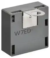
W7ED-11L
Capacitive Touch Sensor, L Shape, Open Collector, 5 to 15VDC, W7ED Series
⚠️ Reference pricing provided. In case of supply shortages, we will connect you with our trusted procurement partners to ensure your project's continuity.
- Manufacturer: OMRON / PARTNER STOCK
- Product type: Capacitive Proximity Sensors
- SVHC: To Be Advised
- Product Range: W7ED Series
- Sensor Output Type: Open Collector
- Supply Voltage DC Max: 15V
- Supply Voltage DC Min: 5V
| Delivery and price | |
|---|---|
| Units per pack | 15 |
| Price | 18.11 € |
| Current stock | 50+ |
| Lead time | 30 days |
Datasheet

**New Product** ~~—~~

## **Touch Sensor W7ED**

## **Reliable operation that requires only a light touch. Models equipped with anti-static FG terminals are also available.**

- Suitable for embedding in equipment

- Enables touch sensor configurations to be created that suit your application. Touch electrodes and touch sensor electrodes can be fastened just using screws.

- Body-to-electrode static electricity transfers can easily be prevented using FG terminal models.

- Supports 5 to 15 VDC, with open-collector output.

Refer to _Safety Precautions_ on page 6.

## **Features**

**No design required** No need to perform sensitivity adjustments or design circuits! Minimizes development man-hours. ~~Lo~~ Achieves reliable operation using a touch electrode that changes capacitance depending on the level of **Reliable operation** Lo touch. Touch electrodes and touch sensors can be fastened just using screws. **Connects easily** Lo

No PCBs, facilitating touch sensor configurations.

**==> picture [231 x 185] intentionally omitted <==**

**----- Start of picture text -----**<br>
[Line-Up]<br>L-shaped electrode type I-shaped electrode type<br>[Mounting example]<br>Touch electrode (conductive material)<br>L-shaped electrode<br>Output<br>=> To main board<br>(L-shaped electrode type)<br>**----- End of picture text -----**<br>


**==> picture [481 x 132] intentionally omitted <==**

**----- Start of picture text -----**<br>
Application Examples<br>^<br>4) & —<br>»  i BS<br>Lights Elevators Vending Machines Faucets<br>^<br>**----- End of picture text -----**<br>


**1** oOmRON ~~a~~

## **W7ED Model Number Legend**

## **W7ED-** @ @ @

**(1) (2) (3)**

- (2) FG terminal

(1) Detected capacitance (2) FG terminal (3) Electrode shape 1: 25 pF 1: Without F: I-shaped 2: With L: L-shaped **Specifications Electrode shape Appearance FG terminal Model** Without W7ED-11F I-shaped With W7ED-12F Without W7ED-11L L-shaped With W7ED-12L ~~Bae oe~~ **2**

**W7ED**

## **Ratings and Specifications**

|**Detected capacitance***|25 ± 5 pF|
|---|---|
|**Power supply voltage**|5 VDC (-10%) to 15 VDC (+10%)|
|**Output**|Open collector (max. output current: 10 mA)|
|**Residual output voltage**|0.4 V max.|
|**Operation mode**|When detecting capacitance (human touch detected): Output transistor ON<br>When not detecting capacitance (no human touch detected): Output transistor OFF|
|**Current consumption**|10 mA max.|
|**Voltage influence**|With rated supply voltage within a range of ±10% and a rate of change for detected capacitance within ±10%<br>when powered using the rated supply voltage|
|**Temperature influence**|Within an ambient temperature range when operating and a rate of change for detected capacitance within ±10%<br>at +23°C|
|**Ambient temperature**|When in use: -10 to 60°C (no icing or condensation)<br>When in storage: -20 to 70°C (no icing or condensation)|
|**Ambient humidity**|25 to 85%RH|


* ”Detected capacitance” refers to the detected capacitance value when capacitance is applied between the electrode and the ground terminal of the touch sensor circuit.

## **Output Circuit Diagram**

**==> picture [506 x 143] intentionally omitted <==**

**----- Start of picture text -----**<br>
FG terminal not provided FG terminal provided<br>(W7ED-11F, W7ED-11L) (W7ED-12F, W7ED-12L)<br>VCC<br>VCC<br>Touch  Touch<br>sensor  sensor  OUT<br>main  OUT main<br>Electrode circuit Electrode circuit Power<br>Power<br>GND supply<br>supply<br>GND<br>FG *<br>**----- End of picture text -----**<br>


- We recommend connecting the FG terminal to a stable potential on the device’s frame ground.

## **Operation Chart**

Capacitance detection

**==> picture [43 x 28] intentionally omitted <==**

**----- Start of picture text -----**<br>
Detected<br>Not detected<br>**----- End of picture text -----**<br>


Output transistor

**==> picture [16 x 28] intentionally omitted <==**

**----- Start of picture text -----**<br>
ON<br>OFF<br>**----- End of picture text -----**<br>


**3**

**W7ED Dimensions**

**(Unit: mm)**

## **W7ED-11F**

**==> picture [415 x 174] intentionally omitted <==**

**----- Start of picture text -----**<br>
2.1<br>5.4<br>Electrode<br>2.65 dia. 5.5<br>2.5±0.2<br>6<br>15±0.2<br>Model<br>Lot No.<br>15±0.2 Trademark 5.5 Terminal symbol<br>(pitch: 1.25) Note: 1. Details of connector terminal symbols are shown below.<br>Connector terminal No. Terminal symbol Name<br>**----- End of picture text -----**<br>


**Note: 1.** Details of connector terminal symbols are shown below.

|**2.**|Compatible housings for connector include 51021-03@@<br>series models from Molex.<br>**Connector terminal No.**<br>**Terminal symbol**<br>**Name**<br>1<br>O<br>Output (OUT)<br>2<br>G<br>Ground (GND)<br>3<br>V<br>Power supply (VCC)|**Terminal symbol**<br>|**Name**<br>|
|---|---|---|---|
|||O|Output (OUT)|
|||G|Ground (GND)|
|||V|Power supply (VCC)|


   **3.** The Lot No. is 4-digit number located at the position indicated in the figure.

- Tolerance class IT16 applies to dimensions in this datasheet unless otherwise specified.

## **W7ED-12F**

**==> picture [160 x 216] intentionally omitted <==**

**----- Start of picture text -----**<br>
2.1<br>5.4<br>2.65 dia.<br>2.5±0.2<br>15±0.2<br>15±0.2 Trademark 5.5<br>(pitch: 1.25)<br>**----- End of picture text -----**<br>


**==> picture [94 x 85] intentionally omitted <==**

**----- Start of picture text -----**<br>
5.5 Electrode<br>6<br>Model<br>Lot No.<br>**----- End of picture text -----**<br>


**==> picture [42 x 7] intentionally omitted <==**

**----- Start of picture text -----**<br>
Terminal symbol<br>**----- End of picture text -----**<br>


**Note: 1.** Details of connector terminal symbols are shown below.

|**Connector terminal No.**<br>**T**|**erminal symbol**<br>|**Name**<br>|
|---|---|---|
|1|O|Output (OUT)|
|2|G|Ground (GND)|
|3|FG|Frame ground (FG)|
|4|V|Power supply (VCC)|


   **2.** Compatible housings for connector include 51021-04 @@ series models from Molex.

   **3.** The Lot No. is 4-digit number located at the position indicated in the figure.

- Tolerance class IT16 applies to dimensions in this datasheet unless otherwise specified.

**4**

**W7ED**

## **W7ED-11L**

**==> picture [80 x 60] intentionally omitted <==**

**----- Start of picture text -----**<br>
5.5±0.2<br>3.1 dia.<br>3.2±0.2<br>**----- End of picture text -----**<br>


**==> picture [414 x 162] intentionally omitted <==**

**----- Start of picture text -----**<br>
Electrode<br>5.5<br>0.15<br>6<br>15±0.2<br>Model<br>Lot No.<br>15±0.2 Trademark 5.5 Terminal symbol<br>11.45±0.2<br>(pitch: 1.25)<br>Note: 1. Details of connector terminal symbols are shown below.<br>Connector terminal No. Terminal symbol Name<br>1 O Output (OUT)<br>2 G  Ground (GND)<br>**----- End of picture text -----**<br>


**Note: 1.** Details of connector terminal symbols are shown below.

|**Connector terminal No.**|**Terminal symbol**|**Name**|
|---|---|---|
|1|O|Output (OUT)|
|2|G|Ground (GND)|
|3|V|Power supply (VCC)|


   **2.** Compatible housings for connector include 51021-03 @@ series models from Molex.

   **3.** The Lot No. is 4-digit number located at the position indicated in the figure.

- Tolerance class IT16 applies to dimensions in this datasheet unless otherwise specified.

## **W7ED-12L**

**==> picture [81 x 60] intentionally omitted <==**

**----- Start of picture text -----**<br>
5.5±0.2<br>3.1 dia.<br>3.2±0.2<br>**----- End of picture text -----**<br>


**==> picture [134 x 99] intentionally omitted <==**

**----- Start of picture text -----**<br>
5.5 Electrode<br>0.15<br>6<br>Model<br>Lot No.<br>Terminal symbol<br>**----- End of picture text -----**<br>


**==> picture [183 x 113] intentionally omitted <==**

**----- Start of picture text -----**<br>
15±0.2<br>Trademark<br>15±0.2 5.5<br>11.45±0.2<br>(pitch: 1.25)<br>**----- End of picture text -----**<br>


**Note: 1.** Details of connector terminal symbols are shown below.

|**Connector terminal No.**<br>**T**<br>|**erminal symbol**<br>|**Name**<br>|
|---|---|---|
|1|O|Output (OUT)|
|2|G|Ground (GND)|
|3|FG|<br>Frame ground (FG)|
|4|V|Power supply (VCC)|


   **2.** Compatible housings for connector include 51021-04 @@ series models from Molex.

   **3.** The Lot No. is 4-digit number located at the position indicated in the figure.

- Tolerance class IT16 applies to dimensions in this datasheet unless otherwise specified.

**5**

## **W7ED**

## **Safety Precautions**

Please read the matters of agreement when ordering

## **How to Use** ~~PO~~

**1.** How to use

   - By connecting and fastening this electrode to a touch electrode (conductive material made from metal or with a metallic plating), a touch sensor configuration can be created with specifications that suit your application. The electrode features a hole that enables it to be fastened with a screw, etc.

**2.** FG terminals

   - Static electricity from the human body, etc., is capable of entering the touch sensor via its electrode. When anti-static measures are required, select a model (W7ED-12F or W7ED-12L) with an FG terminal, which acts as a discharge circuit for static electricity. To enhance the anti-static effects of the FG terminal, we recommend connecting the FG terminal to a stable potential on the device’s frame ground using a thick, short wire.

**I-shaped electrode L-shaped electrode (W7ED-11F, W7ED-12F) (W7ED-11L, W7ED-12L)**

Body (finger) Body (finger) Electrode Screw Touch electrode Touch electrode Screw W7ED Electrode W7ED ~~=P om~~

- **Precautions for Correct Use**

- ~~PO~~ **1.** Use a touch electrode made of conductive metal or metal-plated material.

**2.** Make sure to insulate touch electrode and electrode of this product from external grounds.

**3.** The level of capacitance normally applied will depend on conditions such as the size of the touch electrode or the existence of metal around the touch electrode. Make sure to confirm that the touch sensor operates by applying human touch to the touch electrode with the touch electrode secured in place while in contact with the electrode of this product.

**4.** Avoid use in locations subject to direct contact with liquids such as water. Failure to do so will result in malfunction.

**6**

## **Terms and Conditions Agreement**

## **Read and understand this catalog.**

Please read and understand this catalog before purchasing the products. Please consult your OMRON representative if you have any questions or comments.

## **Warranties.**

(a) Exclusive Warranty. Omron’s exclusive warranty is that the Products will be free from defects in materials and workmanship for a period of twelve months from the date of sale by Omron (or such other period expressed in writing by Omron). Omron disclaims all other warranties, express or implied.

(b) Limitations. OMRON MAKES NO WARRANTY OR REPRESENTATION, EXPRESS OR IMPLIED, ABOUT NON-INFRINGEMENT, MERCHANTABILITY OR FITNESS FOR A PARTICULAR PURPOSE OF THE PRODUCTS. BUYER ACKNOWLEDGES THAT IT ALONE HAS DETERMINED THAT THE PRODUCTS WILL SUITABLY MEET THE REQUIREMENTS OF THEIR INTENDED USE.

Omron further disclaims all warranties and responsibility of any type for claims or expenses based on infringement by the Products or otherwise of any intellectual property right. (c) Buyer Remedy. Omron’s sole obligation hereunder shall be, at Omron’s election, to (i) replace (in the form originally shipped with Buyer responsible for labor charges for removal or replacement thereof) the non-complying Product, (ii) repair the non-complying Product, or (iii) repay or credit Buyer an amount equal to the purchase price of the non-complying Product; provided that in no event shall Omron be responsible for warranty, repair, indemnity or any other claims or expenses regarding the Products unless Omron’s analysis confirms that the Products were properly handled, stored, installed and maintained and not subject to contamination, abuse, misuse or inappropriate modification. Return of any Products by Buyer must be approved in writing by Omron before shipment. Omron Companies shall not be liable for the suitability or unsuitability or the results from the use of Products in combination with any electrical or electronic components, circuits, system assemblies or any other materials or substances or environments. Any advice, recommendations or information given orally or in writing, are not to be construed as an amendment or addition to the above warranty.

See http://www.omron.com/global/ or contact your Omron representative for published information.

## **Limitation on Liability; Etc.**

OMRON COMPANIES SHALL NOT BE LIABLE FOR SPECIAL, INDIRECT, INCIDENTAL, OR CONSEQUENTIAL DAMAGES, LOSS OF PROFITS OR PRODUCTION OR COMMERCIAL LOSS IN ANY WAY CONNECTED WITH THE PRODUCTS, WHETHER SUCH CLAIM IS BASED IN CONTRACT, WARRANTY, NEGLIGENCE OR STRICT LIABILITY.

Further, in no event shall liability of Omron Companies exceed the individual price of the Product on which liability is asserted.

## **Suitability of Use.**

Omron Companies shall not be responsible for conformity with any standards, codes or regulations which apply to the combination of the Product in the Buyer’s application or use of the Product. At Buyer’s request, Omron will provide applicable third party certification documents identifying ratings and limitations of use which apply to the Product. This information by itself is not sufficient for a complete determination of the suitability of the Product in combination with the end product, machine, system, or other application or use. Buyer shall be solely responsible for determining appropriateness of the particular Product with respect to Buyer’s application, product or system. Buyer shall take application responsibility in all cases.

NEVER USE THE PRODUCT FOR AN APPLICATION INVOLVING SERIOUS RISK TO LIFE OR PROPERTY OR IN LARGE QUANTITIES WITHOUT ENSURING THAT THE SYSTEM AS A WHOLE HAS BEEN DESIGNED TO ADDRESS THE RISKS, AND THAT THE OMRON PRODUCT(S) IS PROPERLY RATED AND INSTALLED FOR THE INTENDED USE WITHIN THE OVERALL EQUIPMENT OR SYSTEM.

## **Programmable Products.**

Omron Companies shall not be responsible for the user’s programming of a programmable Product, or any consequence thereof.

## **Performance Data.**

Data presented in Omron Company websites, catalogs and other materials is provided as a guide for the user in determining suitability and does not constitute a warranty. It may represent the result of Omron’s test conditions, and the user must correlate it to actual application requirements. Actual performance is subject to the Omron’s Warranty and Limitations of Liability.

## **Change in Specifications.**

Product specifications and accessories may be changed at any time based on improvements and other reasons. It is our practice to change part numbers when published ratings or features are changed, or when significant construction changes are made. However, some specifications of the Product may be changed without any notice. When in doubt, special part numbers may be assigned to fix or establish key specifications for your application. Please consult with your Omron’s representative at any time to confirm actual specifications of purchased Product.

## **Errors and Omissions.**

Information presented by Omron Companies has been checked and is believed to be accurate; however, no responsibility is assumed for clerical, typographical or proofreading errors or omissions.

Please check each region's Terms & Conditions by region website.

**OMRON Corporation Electronic and Mechanical Components Company**

## **Regional Contact**

**Americas Europe** https://www.components.omron.com/ http://components.omron.eu/ **Asia-Pacific China** https://ecb.omron.com.sg/ https://www.ecb.omron.com.cn/ **Korea Japan** https://www.omron-ecb.co.kr/ https://www.omron.co.jp/ecb/

© OMRON Corporation 2019  All Rights Reserved. In the interest of product improvement, specifications are subject to change without notice.

**Cat. No. A292-E1-02** 0819 (0219)
Updated at June 9, 2026
About Novapart
Novapart is a B2B electronic component broker specialising in stock shortages and cost reduction. We source hard-to-find parts and identify compliant alternatives across a catalogue of 410,000+ components from 500+ manufacturers.
Learn more →Stock Shortage Specialist
When a component is unavailable, discontinued or has an unacceptable lead time, we tap into our network of vetted European and Asian distributors to source what you need — without compromising on quality or traceability.
Request a quote →Compliant Alternatives
We identify pin-to-pin, electrically equivalent substitutes that meet the same certifications (RoHS, AEC-Q100, REACH) as your original specification — validated against datasheets, not just part numbers. Often at a lower cost.
BOM Analysis service →