
Image not available
Illustrative purposes only

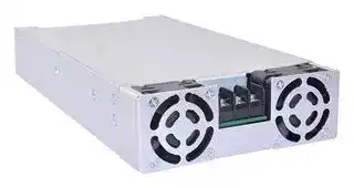
VPS1000-1048
AC/DC Enclosed Power Supply (PSU), ITE, 1 Outputs, 1 kW, 48 VDC, 20.83 A
⚠️ Reference pricing provided. In case of supply shortages, we will connect you with our trusted procurement partners to ensure your project's continuity.
- Manufacturer: EOS POWER
- Product type: AC / DC Enclosed Power Supplies
- SVHC: To Be Advised
- Product Range: VPS1000 Series
- No. of Outputs: 1Outputs
- Output Power Max: 1kW
- Current, Output 4: -
- Input Voltage VAC: 85V AC to 264V AC
- Power Supply Output Type: Adjustable, Fixed
- Output Current - Output 1: 20.83A
- Output Current - Output 2: -
- Output Current - Output 3: -
- Output Voltage - Output 1: 48VDC
- Output Voltage - Output 2: -
- Output Voltage - Output 3: -
- Output Voltage - Output 4: -
- Power Supply Applications: ITE
| Delivery and price | |
|---|---|
| Units per pack | 5 |
| Price | 312.57 € |
| Current stock | 10+ |
| Lead time | 30 days |
Datasheet

**1000 Watt Industrial**

## Features

- l 5 x 9.51 x 1.61 inches

- l Universal input

- l Current Sharing Option

- l Peak Power Capability

- l 5 Vdc Stand by

- l In built – 12 V fan output

- l Power Good / Power Fail Signal

- l Suitable in POE applications

- l ~~Lesser than 1U high~~

- l ~~Having high voltage output range up to 58VDC~~

- l N+1 redundant power supply

- l Single wire current sharing

- l Built in OR-ing diode / FET (- R suffix)

**==> picture [481 x 468] intentionally omitted <==**

**----- Start of picture text -----**<br>
||||
|---|---|---|
|Electrical Specifications|
|Input Voltage|85-264 VAC/120-390 VDC, Universal|
|Input Frequency|47-63 Hz|
|Input Current|120 VAC: 11 A max.|240 VAC: 5.5 A max.|
|Input Protection|F16A/250 V in Live & Neutral both|
|No Load Power|Typ 3W over entire input range with main output kept off using Remote ON/OFF|
|Inrush Current|240 VAC: 25 A max.|
|Leakage Current                                       400 μA @ 240 VAC / 50 Hz                                Touch Current: < 100 μA|
|Efficiency|120 VAC: 88% Typical   240 VAC: 93%|
|Hold-up Time|120 VAC: 8 ms|240 VAC: 8 ms|
|Power Factor|120 VAC: 0.98|240 VAC: 0.95|
|Output Power|1000W Fan Cooled, Peak 1200W for 1mS|
|Line Regulation|+/-0.5%|
|Load Regulation|+/-1%|
|Transient Response|< 10%, 50% to 100% load change, 50 Hz, 50% duty cycle, 0.1 A/µs, recovery time < 5 ms|
|Rise Time|<100 ms|
|Set Point Tolerance|+/-1%|
|Output Adjustability|+/-3%|
|Over Current Protection|110% Typ, HiccUp Type, Autorecovery|
|Over Voltage Protection|114%, Latch Type, AC Power to be recycled for recovery|
|Short Circuit Protection|Latch Type, AC Power to be recycled for recovery|
|Over Temperature Protection|130-140°C primary heat sink, autorecovery|
|Current Share|Upto 3 supplies can be connected in parallel (optional)|
|Switching Frequency|PFC converter:Variable, 85 kHz typical|
|Resonant converter:Variable, 100 kHz typical|
|Operating Temperature|-40 to +70°C, refer derating curve|
|Storage Temperature|-40 to +85°C|
|Relative Humidity|95% Rh, noncondensing|
|Altitude|Operating: 16,000 ft.; Nonoperating: 40,000 ft.|
|MTBF|3.37m Hours, Telcordia -SR332-issue 3|
|44|
|Isolation Voltage|4000 VDC between input to output 2500 VDC input to earth|
|Cooling|Fan Cooled : 1000W|

**----- End of picture text -----**<br>


4EM-20-154                                                                                      1                                                                    39-DE60-41651-002 / A3

|VPS1000-1012                              Fan Cooled                    12V                         41.67 A<br>VPS1000-1030                              Fan Cooled                    30 V                        33.33 A                                       0.0 A                        2%<br>~~VPS1000-1048                              Fan Cooled                    48 V                        20.83 A                                       0.0 A                        2%~~<br>Model Number                        Type                   Voltage              Max. Load                      Min. Load             Ripple|Model Number                        Type                   Voltage              Max. Load                      Min. Load             Ripple1||
|---|---|---|
||VPS1000-1012                              Fan Cooled                    12V                         41.67 A<br>0.0 A                       2%||
||VPS1000-1015                              Fan Cooled                    15 V                        41.67 A<br>0.0 A                       2%||
||VPS1000-1024                              Fan Cooled                    24 V                        41.67 A                                      0.0 A                        2%||
||VPS1000-1030                              Fan Cooled                    30 V                        33.33 A                                       0.0 A                        2%||
||~~VPS1000-1048                              Fan Cooled                    48 V                        20.83 A                                       0.0 A                        2%~~||
|~~VPS1000-1048                              Fan Cooled                    48 V                        20.83 A                                       0.0 A                        2%~~|~~VPS1000-1048                              Fan Cooled                    48 V                        20.83 A                                       0.0 A                        2%~~||
||~~VPS1000-1058                              Fan Cooled                    58 V                       17.24 A                                     0.0 A                        2%~~||
||~~VPS1000-1058                              Fan Cooled                    58 V                       17.24 A                                     0.0 A                        2%~~||


|PinConnections||
|---|---|
|~~J1~~<br>~~1~~<br>~~AC LINE~~|~~AC LINE~~|
|~~2~~<br>~~NEUTRAL~~|~~NEUTRAL~~|
|~~3~~<br>~~EARTH~~|~~EARTH~~|
|~~J2~~<br>~~J2-A~~<br>~~+VE~~|~~+VE~~|
|~~J2-B~~<br>~~-VE~~|~~-VE~~|
|~~J3~~<br>~~Pin 1~~<br>~~GND~~|~~GND~~|
|~~Pin 2~~<br>~~5V AUX~~|~~5V AUX~~|
|~~Pin 3~~<br>~~PGPF~~|~~PGPF~~|
|~~Pin 4~~<br>~~VS -~~|~~VS -~~|
|~~Pin 5~~<br>~~VS +~~|~~VS +~~|
|~~Pin 6~~<br>|~~GND~~|
|~~Pin 7                       RMT~~|~~Pin 7                       RMT~~|
|~~Pin 8~~<br>~~CL2~~|~~CL2~~|
|~~Pin 9                       CL1~~|~~Pin 9                       CL1~~|
|~~Pin 10                     LS~~|~~Pin 10                     LS~~|
|~~J10, J11(Fan Output)             Pin 1                       +VE~~|~~Pin 1                       +VE~~|
|~~Pin 2                       -VE~~|~~Pin 2                       -VE~~|


## ~~Notes~~

~~1. For Ripple measurement minimum output power requirement is 25 W.~~

~~Ripple is peak to peak with 20 MHz bandwidth and 10 µF (Electrolytic  capacitor) in parallel with a 0.1 µF capacitor at rated line voltage and load ranges.~~

~~2. Combined output power of main output, fan supply and standby supply shall not exceed max. power rating.~~

~~3. Standby output voltage  5 V/ 1.5A  with tolerance including set point accuracy, line and load regulation is +/-10%.~~

- ~~Ripple and noise is less than 5%.~~

~~4. Specifcations are for nominal input voltage, 25°C unless otherwise stated.~~

~~5. PSU is supplied with J3, pin-6 and pin-7 shorted to enable main output without remote on/off feature.~~

~~6. Fan supply output voltage is 12V/500mA with regulation band+/-30 % and Ripple is less than 10%. To get 12V Fan supply output voltage, minimum 10 % load on Main output voltage is required.~~

~~Innovatons in Power 2                          39-DE60-41651-002 / A3[EQs]~~

~~4EM-20-154~~

**==> picture [54 x 53] intentionally omitted <==**

**==> picture [511 x 260] intentionally omitted <==**

**----- Start of picture text -----**<br>
Mechanical Specifications<br>AC Input Connector (J1)  TE Connectivity: NC6-P107-03<br>DC Output Connector (J2)  6-32 inches Screw Pan HD<br>Mating: Designed to accept Ring Tongue Terminal AMP : 8-31886-1,<br>                                                                        wherein one 16 AWG(max)  wire can be crimped.<br>Note : One Ring Tongue Terminal with 16 AWG is recommended for current upto 11A only.<br>                                                                        Use multiple tongue terminals with wire for more current.<br>Signal Connector (J3)  Molex: 22-23-2101<br>Mating: 22-01-2107; Pins: 08-50-0113<br>J10, J11 (Fan Output)                                     Make : TE Connectivity AMP Connectors<br>                                                                        Description: CONN HEADER VERT 2POS 2.54MM<br>                                                                        MPN : 640456-2<br>                                                                        Mating : 3-641535-2 / TE Connectivity AMP Connectors OR<br>                                                                        0022013027 / MOLEX with crimping 08-50-0114 / MOLEX<br>Dimensions  5.0 x 9.51 x 1.61 inches<br>(127 x 241.5 x 41 mm)<br>Weight   1.3 kg<br>**----- End of picture text -----**<br>


**==> picture [511 x 61] intentionally omitted <==**

**----- Start of picture text -----**<br>
EMC<br>     Parameter      Conditions/Description      Criteria<br>Conducted Emissions EN 55032 Class B<br>**----- End of picture text -----**<br>


|Radiated Emissions|EN 55032|Class A(Class B with External kingcore|
|---|---|---|
|||K5B RC 25x12x15-M or equivalent)|
|Input Current Harmonics|EN 61000-3-2|Class A|
|Voltage Fluctuation and Flicker|EN 61000-3-3|Complies|
|ESD Immunity|EN 61000-4-2|A|
|Radiated Field Immunity|EN 61000-4-3|A|
|Electrical Fast Transient Immunity|EN 61000-4-4|A|
|Surge Immunity|EN 61000-4-5|A|
|Conducted Immunity|EN 61000-4-6|A|
|Magnetic Field Immunity|EN 61000-4-8|A|
|Voltage dips, interruptions|EN 61000-4-11|A & B|
||Safety||
|CE Mark|Complies with LVD Directive||
|Approval Agency|Nemko, UL, C-UL||
|Safety Standard(s)|IEC/EN62368-1,ED 2||
||UL62368,CSA C22-2 NO- 62368-1||
|Safety File Number(s)|UL Certifcate No : 20190313-E150565||
||CB Test Certifcate No : NO105325||
||Nemko Certifcate No : P19223362||


4EM-20-154                                                                                          3                                                                39-DE60-41651-002 / A3

||||Signal(s)|||
|---|---|---|---|---|---|
|Power Good / Power Fail Signal|Power Good : Is a TTL signal which goes high after main output reaches 90% of its set value.|||Power Good : Is a TTL signal which goes high after main output reaches 90% of its set value.||
|The delay is 0.1 s to 0.5 s||||||
||Power Fail : The same signal goes low at least 1ms before main output falls to 90% of set||Power Fail : The same signal goes low at least 1ms before main output falls to 90% of set|||
|value at AC Power off||||||
|||V||||
||||90%Vout|90%Vout||
||||1<br>1|||
||Vout||t<br>H|||
||||11|||
||||11|||
||||11|||
||||11|||
||||11|||
||||11|||
||||1<br>1|||
||.<br>Signal||1<br>1|||
|||||T||
||||100- 500mS<br>> 1mS|||
||||Power Good<br>Power|Fail||
|Remote Sense|Compensates for 200 mV drop|||||
|Remote on/off|Pin 6 & Pin 7 of J3 can be used for Remote on/off.|Pin 6 & Pin 7 of J3 can be used for Remote on/off.||||
||Shorting Pin 6 to Pin 7 enables main output while keeping the pins open disables main output|||||
||Note:-Provision of Inhibit Remote ON/OFF is available. +5V at Pin 7 will switch off the main output.||Provision of Inhibit Remote ON/OFF is available. +5V at Pin 7 will switch off the main output.|||
|OCP limit set|Pin 8 & Pin 9 of J3 must be shorted|Pin 8 & Pin 9 of J3 must be shorted||||


©: Innovations in Power 4EM-20-154 4                    39-DE60-41651-002 / A3

## Derating Curve

**==> picture [112 x 12] intentionally omitted <==**

**----- Start of picture text -----**<br>
Derating Curve w.r.t Input<br>**----- End of picture text -----**<br>


## Derating Curve for 12 V

De-rate between 30-50 °C @ 0.833% per °C De-rate above 50 °C @ 2.5% per °C

4EM-20-154                                                                                          5                                                                39-DE60-41651-002 / A3

**==> picture [545 x 700] intentionally omitted <==**

**----- Start of picture text -----**<br>
Derating Curve<br>Derating Curve for 15 V<br>700<br>600<br>500<br>De-rate between 30-50 °C @ 0.833% per °C<br>De-rate above 50 °C @ 2.5% per °C<br>= 200<br>ot<br>=<br>-0 PLE ELLE L LLL. ° °<br>-40 -30 -20 = -10 0 100 700d BO—Cis—“( <ésése OCU<br>Amb Temp (*C}<br>Derating Curve for 24 V & above<br>ee a<br>ee900 eeee ee ee<br>- 700<br>eg ee De-rate between 30-50 °C @ 0.833% per °C<br>:eee500 De-rate above 50 °C @ 2.5% per °C<br>eo& 400 |i | | | | |] ff<br>goof | | | | | tT | dt |<br>TTT<br>ee OO<br>sSeEL_IT0 TTT TT yy<br>-40 -30 -20 -10 o 100«Ca2si =e] ss t—“ ‘Be ti—‘ia8SCSF<br>Amb Temp (*C)<br>Innovations in Power<br>                                                           4EM-20-154               6                              39-DE60-41651-002 / A3<br>**----- End of picture text -----**<br>


**==> picture [91 x 12] intentionally omitted <==**

**----- Start of picture text -----**<br>
Mechanical Drawing<br>**----- End of picture text -----**<br>


4EM-20-154                                                                                                7                                                          39-DE60-41651-002 / A3

## Installtion instruction for current sharing:

During the installation and setup of parallel supplies in a system it is important that a single remote sense point be used for all the supplies. Mechanical Drawing The remote sense voltage between the supplies must be adjusted to within 1% to ensure the supplies are inside the 1% capture window. If the supplies are not initially adjusted inside the capture window the supplies will not current share satisfactorily.

## Set-Up Procedures:

1. Connect load cables to the outputs of each supply.

2. Connect the remote sense lines to the load in twisted style . (A common remote sense point must be used for all the supplies in parallel).

3. Connect all the “LS” signal(Pin 10) on the J3 connector between the supplies.

4. Adjust remote sense voltage of each supply to within 1% of rated output voltage or readjust to required set point. (Adjustment to be done with all other parallel supplies off).

5. Current sharing between the supplies can be verified by monitoring the output current of each supply with a hall effect DC current probe. The supplies should share to within 10% of the total load current.

The maximum recommended power output for three units in parallel would be 2700W.

6. The current share circuit has a capture window voltage of +/- 1% of the rated output voltage. If the output remote sense voltage of one of the supplies is adjusted outside the 1% window the supplies will not current share satisfactorily.

**51** Innovations in Power 4EM-20-154 8                          39-DE60-41651-002 / A3
Updated at June 4, 2026
About Novapart
Novapart is a B2B electronic component broker specialising in stock shortages and cost reduction. We source hard-to-find parts and identify compliant alternatives across a catalogue of 410,000+ components from 500+ manufacturers.
Learn more →Stock Shortage Specialist
When a component is unavailable, discontinued or has an unacceptable lead time, we tap into our network of vetted European and Asian distributors to source what you need — without compromising on quality or traceability.
Request a quote →Compliant Alternatives
We identify pin-to-pin, electrically equivalent substitutes that meet the same certifications (RoHS, AEC-Q100, REACH) as your original specification — validated against datasheets, not just part numbers. Often at a lower cost.
BOM Analysis service →