
Image not available
Illustrative purposes only

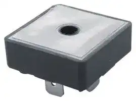
VBO25-12NO2
Bridge Rectifier, Single Phase, 1.2 kV, 38 A, FO-A, 4 Pins, 1.36 V
⚠️ Reference pricing provided. In case of supply shortages, we will connect you with our trusted procurement partners to ensure your project's continuity.
- Manufacturer: IXYS SEMICONDUCTOR
- Product type: Bridge Rectifier Diodes
- No. of Phases:Single Phase; Repetitive Reverse Voltage Vrrm Max:1.2kV; Forward Current If(AV):38A; Bridge Rectifier Case Style:FO-A; Forward Voltage VF Max:1.36V; No. of Pins:4Pins; O
- SVHC: No SVHC (12-Jan-2017)
- No. of Pins: 4Pins
- No. of Phases: Single Phase
- Product Range: VBO25
- Forward Voltage Max: 1.36V
- Forward Surge Current: 370A
- Average Forward Current: 38A
- Bridge Rectifier Mounting: Panel Mount
- Operating Temperature Max: 150°C
- Bridge Rectifier Case Style: FO-A
- Repetitive Peak Reverse Voltage: 1.2kV
| Delivery and price | |
|---|---|
| Units per pack | 100 |
| Price | 15.51 € |
| Current stock | 10+ |
| Lead time | 30 days |
Datasheet

**VBO 25** ## **Single Phase Rectifier Bridge** ## **I** dAV **= 38 A VRRM = 800-1600 V** Standard and Avalanche Types **==> picture [7 x 82] intentionally omitted <==** **----- Start of picture text -----**<br> +<br>~<br>~<br>-<br>**----- End of picture text -----**<br> |**VRSM**||**VBRmin**||**VRRM**||**Standard**||**Avalanche**| |---|---|---|---|---|---|---|---|---| |**V**||**V**||**V**||**Types**||**Types**| |**900**||||**800**||**VBO 25-08NO2**||| |**1300**||**1230**||**1200**||**VBO 25-12NO2**||**VBO 25-12AO2**| |**1700**||**1630**||**1600**||**VBO 25-16NO2**||**VBO 25-16AO2**| For Avalanche Type only |**Symbol**<br>**IdAV **<br>**IdAVM**<br>**PRSM**<br>**IFSM**||**Conditions**<br>TC= 85°C, module<br>module<br>TVJ= TVJM<br>TVJ= 45°C;<br>t = 10 ms<br>(50 Hz)<br>VR= 0<br>t = 8.3 ms<br>(60 Hz)||**Maximum Ratings**<br>38<br>40<br>3.4<br>A<br>A<br>kW<br>370<br>390<br>A<br>A| |---|---|---|---|---| |||TVJ= TVJM;<br>t = 10 ms<br>(50 Hz)||320<br>A| |||VR= 0<br>t = 8.3 ms<br>(60 Hz)||340<br>A| |**I2t**||TVJ= 45°C;<br>t = 10 ms<br>(50 Hz)||680<br>A2s| |||VR= 0<br>t = 8.3 ms<br>(60 Hz)<br>TVJ= TVJM;<br>t = 10 ms<br>(50 Hz)<br>VR= 0<br>t = 8.3 ms<br>(60 Hz)||640<br>A2s<br>510<br>470<br>A2s<br>A2s| |**TVJ**||||-40...+150<br>°C| |**TVJM**||||150<br>°C| |**Tstg**<br>**VISOL**||50/60 Hz, RMS<br>t = 1 min<br>IISOL<1 mA<br>t = 1 s||-40...+125<br>°C<br>3000<br>3600<br>V~<br>V~| |**Md**<br>Mounting torque (M5)<br>(10-32 UNF)<br>1.5-2<br>13-18<br>Nm<br>lb.in.<br>**Weight**<br>Typ.<br>15<br>g<br>~~ODOT~~<br>~~rs~~||||| |**Symbol**||**Conditions**||**Characteristic Values**| |**IR**<br>VR= VRRM<br>TVJ= 25°C<br> <br>TVJ= TVJM<br>0.3<br>5.0<br>mA<br>mA<br>**VF**<br>IF= 55 A<br>TVJ= 25°C<br>1.36<br>V<br>~~es~~||||| |**VT0**<br>**rt**<br>For power-loss calculations only<br>0.85<br>8<br>V<br>mΩ<br>**RthJC**<br>**RthJH**<br>per diode; 120° el.<br>per module<br>per diode; 120° el.<br>per module<br>2.80<br>0.70<br>3.20<br>0.80<br>K/W<br>K/W<br>K/W<br>K/W<br>~~a~~<br>~~a~~||||| |**dS**||Creeping distance on surface||13<br>mm| |**dA**||Creepage distance in air||9.5<br>mm| |**a**||Max. allowable acceleration||50<br>m/s2| **==> picture [8 x 5] intentionally omitted <==** **----- Start of picture text -----**<br> -<br>**----- End of picture text -----**<br> ## **Features** - •Avalanche rated parts available - •Package with DCB ceramic base plate - •Isolationvoltage 3600 V~ - •Planarpassivated chips - •Low forward voltage drop - •¼"fast-on terminals - •ULregisteredE72873 ## **Applications** - •Suppliesfor DC power equipment - Input rectifiers for PWM inverter - Battery DC power supplies - Field supply for DC motors ## **Advantages** - •Easytomountwithonescrew - Space and weight savings - Improved temperature & power cycling ## **Dimensions in mm (1 mm = 0.0394“)** Data according to IEC 60747 and refer to a single diode unless otherwise stated. for resistive load at bridge output - with isolated fast-on tabs. IXYS reserves the right to change limits, test conditions and dimensions. © IXYS All rights reserved 20100706b 1 - 2 **VBO 25** Fig. 1 Surge overload current per diode Fig. 2 I[2] t versus time (1-10 ms) IFSM: Crest value, t: duration per diode Fig. 3 Max. forward current at case temperature Fig. 4 Power dissipation versus direct output current and ambient temperature Constants for ZthJK calculation: |**i**|**Rthi (K/W)**|**ti (s)**| |---|---|---| |1|0.775|0.0788| |2|1.390|0.504| |3|1.055|3.701| Fig. 5 Transient thermal impedance junction to heatsink per diode IXYS reserves the right to change limits, test conditions and dimensions. © IXYS All rights reserved 20100706b 2 - 2
Updated at June 4, 2026
About Novapart
Novapart is a B2B electronic component broker specialising in stock shortages and cost reduction. We source hard-to-find parts and identify compliant alternatives across a catalogue of 410,000+ components from 500+ manufacturers.
Learn more →Stock Shortage Specialist
When a component is unavailable, discontinued or has an unacceptable lead time, we tap into our network of vetted European and Asian distributors to source what you need — without compromising on quality or traceability.
Request a quote →Compliant Alternatives
We identify pin-to-pin, electrically equivalent substitutes that meet the same certifications (RoHS, AEC-Q100, REACH) as your original specification — validated against datasheets, not just part numbers. Often at a lower cost.
BOM Analysis service →