
Image not available
Illustrative purposes only

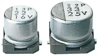
UWF1C470MCL1GB
ALUMINUM ELECTROLYTIC CAPACITOR 47UF 16V 20%, SMD
⚠️ Reference pricing provided. In case of supply shortages, we will connect you with our trusted procurement partners to ensure your project's continuity.
- Manufacturer: NICHICON
- Product type: SMD Aluminium Electrolytic Capacitors
- Polarity: Polar
- Capacitance: 47µF
- Voltage(DC): 16V
- Product Height: 6.2mm
- Product Diameter: 6.3mm
- Capacitor Terminals: Solder
- Capacitance Tolerance: ± 20%
- Lifetime @ Temperature: 2000 hours @ 85°C
- Capacitor Case / Package: Radial Can - SMD
- Operating Temperature Max: 105°C
- Operating Temperature Min: -55°C
| Delivery and price | |
|---|---|
| Units per pack | 2000 |
| Price | 0.227 € |
| Current stock | 10+ |
| Lead time | 30 days |
Datasheet

**ALUMINUM  ELECTROLYTIC  CAPACITORS**

## **UWF**

Chip Type,  Low Impedance

Chip type,  low impedance temperature range up to +105°C. Designed for surface mounting on high density PC board. Applicable to automatic mounting machine fed with carrier tape. Compliant to the RoHS directive (2011/65/EU).

**UWG** LowImpedance **UWF** LowImpedance **UWT** Specifications oe ae Item Performance Characteristics ~~cc~~ Category Temperature Range – 55 to +105°C Rated Voltage Range 6.3 to 35V Rated Capacitance Range 1 to 220µF Capacitance Tolerance ± 20% at 120Hz, 20°C Leakage Current After 2 minutes' application of rated voltage,  leakage current is not more than 0.01CV or 3 (µA) ,  whichever is greater. Measurement frequency : 120Hz at 20°C Tangent of loss angle (tan δ) Rated voltage (V) 6.3 10 16 25 35 tan  δ   (  MAX.) 0.22 0.19 0.16 0.14 0.12 ~~So ee~~ Measurement frequency : 120Hz ~~e~~ Rated voltage (V) 6.3 10 16 25 35 Stability at Low Temperature Impedance ratio Z–25°C / Z+20°C 2 2 2 2 2 ZT / Z20 (MAX.) Z–55°C / Z+20°C 4 4 3 3 3 The specifications listed at right shall be met when Capacitance change Within ±20% of the initial capacitance value Endurance the capacitors are restored to 20°C after the rated tan δ 200% or less than the initial specified value voltage is applied for 1000 hours at 105°C. Leakage current Less than or equal to the initial specified value ~~SS~~ Shelf Life After storing the capacitors under no load at 105°C for 1000 hours and then performing voltage treatment based on JIS C 5101-4 clause 4.1 at ~~Ee~~ 20°C, they shall meet the specified values for the endurance characteristics listed above. Resistance to solderingheat The capacitors are kept on a hot plate for 30 seconds, which is maintained at 250°C. The capacitors shall meet thecharacteristic requirements listed at right when they are removed Ctan apδacitance change Within ±10% of the initial caLess than or equal to the initial spacitance valuepecified value ~~a~~ from the plate and restored to 20°C. Leakage current Less than or equal to the initial specified value

Marking

Black print on the case top.

## Chip Type

(φ4 to φ6.3) Type numbering system  (Example : 16V 10µF) 105˚C Marking Positive CapacitanceLot No. VoltagePlastic platform0.3 MAX. C±0.2 U1 W2 F3 14 C5 16 07 08 M9 C10 11L 121 G13 B14 φD Code ~~aAl LULL == =~~ 4 to 6.38 GBGS Taping code Configuration 5.4 +0.1-0.2 0.5 to 0.8 Capacitance tolerance (±20%) | ~~} FA,~~ Negative (105˚C Marking ~~“~~ Capacitanceφ8) B ~~i~~ Plastic platform n 0.3 MAX. ~~fes~~ C±0.2 Positive A φD 1.84 2.15 6.32.4 (mm) 3.38 ~~=~~ Rated capacitance (10µF) Rated voltage (16V) Series name Trade mark Voltage B 4.3 5.3 6.6 8.3 Type ~~e~~ C 4.3 5.3 6.6 8.3 E 1.0 1.3 2.2 2.3 Lot No. [ sq]TP ~~AL SHH~~ 6.2±0.3 0.5 to 0.8 ~~e~~ . Dimensions r ~~mia~~ e ~~**n** eNe~~ Negative 7 Voltage mark for 6.3V is 6V. V **6.3 10 16 25** — **35** ~~===~~ Cap. (µF) Code 0J 1A 1C 1E 1V **1** 010 4 5.0 50 **1.5** 1R5 4 5.0 50 **2.2** 2R2 4 5.0 50 ~~=~~ **3.3** 3R3 4 5.0 50 **4.7** 4R7 4 5.0 50 4 5.0 50 **6.8** 6R8 4 5.0 50 5 2.6 80 ~~ee~~ **10** 100 ~~ee~~ 4 5.0 50 5 2.6 80 5 2.6 80 **15** 150 5 2.6 80 6.3 1.3 115 6.3 1.3 115 **22** 220 4 5.0 50 5 2.6 80 5 2.6 80 6.3 1.3 115 6.3 1.3 115 **33** 330 5 2.6 80 5 2.6 80 6.3 1.3 115 6.3 1.3 115 8 0.8 150 ~~=~~ **47** 470 5 2.6 ~~===~~ 80 6.3 1.3 115 6.3 1.3 115 8 0.8 150 8 0.8 150 **68** 680 6.3 1.3 115 6.3 1.3 115 8 0.8 150 8 0.8 150 **100** 101 6.3 1.3 115 8 0.8 150 8 0.8 150 **150220** 151221 88 0.80.8 150 150 8 0.8 150 Case sizeφ D (mm) Impedance Rated ripple Max. Impedance  (Ω) at 20°C 100kHz Frequency coefficient of rated ripple current Rated ripple current (mArms) at 105°C 100kHz Frequency 50 Hz 120 Hz 300 Hz 1 kHz 10 kHz or more Taping specifications are given in page 23. Coefficient 0.35 0.50 0.64 0.83 1.00 Recommended land size, soldering by reflow are given in page 18, 19. Please select UUJ(p.158)  if high C/V products are reqired. Please refer to page 3 for the minimum order quantity. 113 CAT.8100E ~~eee Bo~~ |
Updated at February 9, 2023
About Novapart
Novapart is a B2B electronic component broker specialising in stock shortages and cost reduction. We source hard-to-find parts and identify compliant alternatives across a catalogue of 410,000+ components from 500+ manufacturers.
Learn more →Stock Shortage Specialist
When a component is unavailable, discontinued or has an unacceptable lead time, we tap into our network of vetted European and Asian distributors to source what you need — without compromising on quality or traceability.
Request a quote →Compliant Alternatives
We identify pin-to-pin, electrically equivalent substitutes that meet the same certifications (RoHS, AEC-Q100, REACH) as your original specification — validated against datasheets, not just part numbers. Often at a lower cost.
BOM Analysis service →