
Image not available
Illustrative purposes only

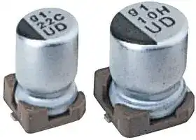
UUD1E100MCL1GS
ALUMINUM ELECTROLYTIC CAPACITOR 10UF 25V 20%, SMD
⚠️ Reference pricing provided. In case of supply shortages, we will connect you with our trusted procurement partners to ensure your project's continuity.
- Manufacturer: NICHICON
- Product type: SMD Aluminium Electrolytic Capacitors
- Polarity: Polar
- Capacitance: 10µF
- Voltage(DC): 25V
- Product Height: 5.8mm
- Product Diameter: 4mm
- Capacitor Terminals: Solder
- Capacitance Tolerance: ± 20%
- Lifetime @ Temperature: 2000 hours @ 105°C
- Capacitor Case / Package: Radial Can - SMD
- Operating Temperature Max: 105°C
- Operating Temperature Min: -55°C
| Delivery and price | |
|---|---|
| Units per pack | 100 |
| Price | 0.191 € |
| Current stock | 10+ |
| Lead time | 30 days |
Datasheet

**ALUMINUM  ELECTROLYTIC  CAPACITORS**

## **UUD**

Chip Type, Low Impedance

Chip type, low impedance temperature range up to +105°C. Designed for surface mounting on high density PC board. Applicable to automatic mounting machine fed with carrier tape. Compliant to the RoHS directive (2011/65/EU).

**UWD** High Temp reflow (t} **UCD** Low Impedance **UUD** Low Impedance **UWG** aL

## Specifications

Specifications Item Performance Characteristics ~~—~~ Category Temperature Range –55 to +105°C Rated Voltage Range 6.3 to 50V ~~Ee~~ Rated Capacitance Range 1 to 1500µF Capacitance Tolerance ± 20% at 120Hz, 20°C ~~a~~ Leakage Current After 2 minutes' application of rated voltage, leakage current is not more than 0.01 CV or 3 (µA), whichever is greater. Measurement frequency : 120Hz at 20°C Tangent of loss angle (tan δ) Rated voltage (V) 6.3 10 16 25 35 50 tan  δ (MAX.) 0.26 (0.28) 0.20 (0.24) 0.16 (0.20) 0.14 (0.16) 0.12 (0.14) 0.12 (0.14) (    ) is φ8 over ~~(Ee~~ Measurement frequency : 120Hz Rated voltage (V) 6.3 10 16 25 35 50 Stability at Low Temperature Impedance ratio Z–25°C / Z+20°C 3 2 2 2 2 2 ZT / Z20 (MAX.) Z– 55°C / Z+20°C 5 4 4 3 3 3 ~~_~~ The specifications listed at right shall be met ~~eee~~ Capacitance change Within ±30% of the initial capacitance value Endurance when the capacitors are restored to 20°C after the rated voltage is applied for 5000 hours (2000 tan δ 200% or less than the initial specified value Leakage current Less than or equal to the initial specified value hours for φD = 4, 5 and 6.3) at 105°C. ~~PES~~ Shelf Life After storing the capacitors under no load at 105°C for 1000 hours and then performing voltage treatment based on JIS C 5101-4 clause 4.1 at 20°C, they shall meet the specified values for the endurance characteristics listed above. ~~I~~ Resistance to soldering The capacitors are kept on a hot plate for 30 seconds, which is maintained at 250°C. The capacitors shall meet the characteristic Catan pδacitance change Within ±10% of the initial caLess than or equal to the initial spacitance valuepecified value heat requirements listed at right when they are removed from the plate ~~a~~ and restored to 20°C. Leakage current Less than or equal to the initial specified value Marking Black print on the case top.

> Chip Type Type numbering system  (Example : 16V 22µF) (φ4 to φ6.3) Positive 1 2 3 4 5 6 7 8 9 10 11 12 13 14

> Plastic platform U U D 1 C 2 2 0 M C L 1 G S Voltage (C:16V) Series 0.3 MAX. C±0.2 Package code Configuration Capacitance tolerance (±20%) φ D Code 4 to 6.3 CL ~~@~~ Lot No. Capacitance ~~I~~ O L±0.3 ~~N THES~~ H Negative Rated capacitance (22μF) ~~==~~ 8 • 10 NL Rated voltage (16V) Series name ~~oa@~~ jit Type ~~.~~ (φ8 to φ10 ) Positive Plastic platform Trade markVoltage (V:35V) Series 0.3 MAX. C±0.2 φ D × LD × L 4 × 5.8 5 × 5.8 6.3 × 5.8 6.3 × 7.7 8 × 10 10 × 10(mm) A 1.8 2.1 2.4 2.4 2.9 3.2 Sa ~~Sieh~~ =====eS B 4.3 5.3 6.6 6.6 8.3 10.3 C 4.3 5.3 6.6 6.6 8.3 10.3 E 1.0 1.3 2.2 2.2 3.1 4.5 Lot No. Capacitance L±0.5 H Negative HLL 0.5 to 0.85.85.8 0.5 to 0.85.85.8 0.5 to 0.85.85.8 0.5 to 0.87.77.7 0.8 to 1.11010 0.8 to 1.11010 Pressure relief vent |__ ~~| sk~~ a

**==> picture [218 x 86] intentionally omitted <==**

**----- Start of picture text -----**<br>
(mm)<br>φ D × LD × L 4 × 5.8 5 × 5.8 6.3 × 5.8 6.3 × 7.7 8 × 10 10 × 10(mm)<br>A 1.8 2.1 2.4 2.4 2.9 3.2<br>=====eS B 4.3 5.3 6.6 6.6 8.3 10.3<br>C 4.3 5.3 6.6 6.6 8.3 10.3<br>E 1.0 1.3 2.2 2.2 3.1 4.5<br>a HLL 0.5 to 0.85.85.8 0.5 to 0.85.85.8 0.5 to 0.85.85.8 0.5 to 0.87.77.7 0.8 to 1.11010 0.8 to 1.11010<br>**----- End of picture text -----**<br>


Voltage V 6.3 10 16 25 35 50 ~~——~~ Code j A C E V H

Dimension table in next page.

133 |

Ld CAT.8100E

**ALUMINUM  ELECTROLYTIC  CAPACITORS**

## **UUD**

## Dimensions

|V<br>Code<br>Cap.<br>(µF)|V<br>Code<br>Cap.<br>(µF)|**6.3**|**6.3**|**6.3**|**10**|**10**|**10**|**16**|**16**|**16**|**25**|**25**|**25**|**35**|**35**|**35**|**50**|**50**|**50**|
|---|---|---|---|---|---|---|---|---|---|---|---|---|---|---|---|---|---|---|---|
|||0J|||1A|||1C|||1E|||1V|||1H|||
|**1**|010||||||||||||||||4×5.8|5.00|30|
|**2.2**|2R2||||||||||||||||4×5.8|5.00|30|
|**3.3**|3R3||||||||||||||||4×5.8|5.00|30|
|**4.7**|4R7|||||||||||||4×5.8|1.80|80|5×5.8|1.52|85|
|**10**|100||||||||||4×5.8|1.80|80|5×5.8|0.76|150|6.3×5.8|0.88|165|
|**15**|150|||||||4×5.8<br>|1.80|80|5×5.8|0.76|150|5×5.8|0.76|150|6.3×5.8|0.88|165|
|**22**|220||||4×5.8|1.80|80|5×5.8<br>|0.76<br>|150|5×5.8|0.76|150|5×5.8|0.76|150|6.3×5.8|0.88|165|
|**27**|270|4×5.8|1.80|80|5×5.8|0.76|150|5×5.8<br>|0.76<br>|150|6.3×5.8|0.44|230|6.3×5.8|0.44|230|6.3×7.7|0.68|185|
|**33**|330|5×5.8|0.76|150|5×5.8|0.76|150<br>|6.3×5.8<br>|0.44<br>|230|6.3×5.8|0.44|230|6.3×5.8|0.44|230|6.3×7.7|0.68|185|
|**47**|470|5×5.8|0.76|150|6.3×5.8|0.44|230<br>|6.3×5.8<br>|0.44<br>|230|6.3×5.8|0.44|230|6.3×5.8|0.44|230|6.3×7.7|0.68|185|
|**56**|560|5×5.8|0.76|150|6.3×5.8|0.44|230<br>|6.3×5.8<br>|0.44<br>|230|6.3×5.8|0.44|230|6.3×7.7|0.34|280|8×10|0.34|300|
|**68**|680|6.3×5.8|0.44|230|6.3×5.8|0.44|230<br>|6.3×5.8<br>|0.44<br>|230|6.3×5.8|0.44|230|6.3×7.7|0.34|280|8×10|0.34|300|
|**100**|101|6.3×5.8|0.44|230|6.3×5.8|0.44|230<br>|6.3×5.8<br>|0.44<br>|230|6.3×7.7|0.34|280|8×10|0.17|450|8×10|0.34|300|
|**150**|151|6.3×5.8|0.44|230|6.3×5.8|0.44|230<br>|6.3×7.7<br>|0.34<br>|280|8×10|0.17|450|8×10|0.17|450|10×10|0.18|670|
|**220**|221|6.3×5.8|0.44|230|6.3×7.7|0.34|280<br>|6.3×7.7<br>|0.34<br>|280|8×10|0.17|450|8×10|0.17|450|10×10|0.18|670|
|**330**|331|6.3×7.7|0.34|280|8×10|0.17|450|8×10<br>|0.17<br>|450|8×10|0.17|450|10×10|0.09|670||||
|**470**|471|8×10|0.17|450|8×10|0.17|450|8×10<br>|0.17<br>|450|10×10|0.09|670|||||||
|**680**|681|8×10|0.17|450|10×10|0.09|670<br>|10×10<br>|0.09<br>|670||||||||||
|**1000**|102|8×10|0.17|450|10×10|0.09|670||||||||||Case size<br>φD×L (mm)|Impedance|Rated<br>ripple|
|**1500**|152|10×10|0.09|670||||||||||||||||


Max. Impedance (Ω) at 20°C 100kHz, Rated ripple current (mArms) at 105°C 100kHz

## Frequency coefficient of rated ripple current

|Frequency|50 Hz|120 Hz|300 Hz|1 kHz|10 kHz or more|
|---|---|---|---|---|---|
|Coefficient|0.35|0.50|0.64|0.83|1.00|


Taping specifications are given in page 23. Recommended land size, soldering by reflow are given in page 18, 19.

Please refer to page 3 for the minimum order quantity.

CAT.8100E

134
Updated at February 9, 2023
About Novapart
Novapart is a B2B electronic component broker specialising in stock shortages and cost reduction. We source hard-to-find parts and identify compliant alternatives across a catalogue of 410,000+ components from 500+ manufacturers.
Learn more →Stock Shortage Specialist
When a component is unavailable, discontinued or has an unacceptable lead time, we tap into our network of vetted European and Asian distributors to source what you need — without compromising on quality or traceability.
Request a quote →Compliant Alternatives
We identify pin-to-pin, electrically equivalent substitutes that meet the same certifications (RoHS, AEC-Q100, REACH) as your original specification — validated against datasheets, not just part numbers. Often at a lower cost.
BOM Analysis service →