
Image not available
Illustrative purposes only

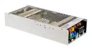
UHP-2500-24
AC/DC Enclosed Power Supply (PSU), 250 to 370VDC, ITE, 1 Outputs, 2.5008 kW, 24 VDC, 104.2 A
⚠️ Reference pricing provided. In case of supply shortages, we will connect you with our trusted procurement partners to ensure your project's continuity.
- Manufacturer: MEAN WELL
- Product type: AC / DC Enclosed Power Supplies
- SVHC: No SVHC (25-Jun-2025)
- Product Range: UHP-2500 Series
- No. of Outputs: 1Outputs
- Output Power Max: 2.5008kW
- Input Voltage VAC: 90V AC to 264V AC
- Power Supply Output Type: Adjustable, Fixed
- Output Current - Output 1: 104.2A
- Output Current - Output 2: -
- Output Current - Output 3: -
- Output Current - Output 4: -
- Output Voltage - Output 1: 24VDC
- Output Voltage - Output 2: -
- Output Voltage - Output 3: -
- Output Voltage - Output 4: -
- Power Supply Applications: ITE
| Delivery and price | |
|---|---|
| Units per pack | 1 |
| Price | 635.83 € |
| Current stock | 10+ |
| Lead time | 30 days |
Datasheet

> 2500W  Conduction Cooling with PFC Switching Supply **UHP - 2500 series**

W ~~A~~ Ns **UL62368-1** B **TPTC004** til **IEC62368-1** CB CE ■

## ■

> - 30 ~+ 70 ℃

## ■

> ℃ ~70 ℃

## ■

_File Name:UHP-2500-SPEC   2020-06-08_

**UHP - 2500 series**

2500W  Conduction Cooling with PFC Switching Supply

## **SPECIFICATION**

|**VOLTAGE ADJ. RANGE**<br>105 ~ 115% rated output power<br>**MODEL**<br>**DC VOLTAGE**<br>**RATED CURRENT**<br>**OUTPUT**<br>**LINE REGULATION**<br>**LOAD REGULATION**<br>**SETUP, RISE TIME**<br>**HOLD UP TIME (Typ.)**<br>**VOLTAGE RANGE**<br>**Note.4**<br>**FREQUENCY RANGE**<br>**POWER FACTOR (Typ.)**<br>**EFFICIENCY (Typ.)**<br>**INPUT**<br>**INRUSH CURRENT (Typ.)**<br>**LEAKAGE CURRENT**<br>**OVER TEMPERATURE**<br>**WORKING TEMP.**<br>**WORKING HUMIDITY**<br>**STORAGE TEMP., HUMIDITY**<br>**TEMP. COEFFICIENT**<br>**VIBRATION**<br>**DIMENSION**<br>**OTHERS**<br>**NOTE**<br>**OVERLOAD**<br>**OVER VOLTAGE**<br>**AC CURRENT (Typ.)**<br>1800ms, 60ms/230VAC at full load<br>90 ~ 264VAC          250 ~ 370VDC<br>Cold start 60A/230VAC<br><0.75mA / 240VAC<br>-30 ~ +70<br>(Refer to “Derating Curve")<br>℃<br>20 ~ 90% RH non-condensing<br>-40 ~ +85<br>, 10 ~ 95% RH non-condensing<br>℃<br>±<br>℃<br>℃)<br>0.03%/<br>(0 ~ 50<br>10 ~ 500Hz, 2G 10min./1cycle, 60min. each along X, Y, Z axes<br>166.12K hrs min.<br>Telcordia SR-332 (Bellcore) ; 48.91K hrs min.      MIL-HDBK-217F (25<br>)<br>℃<br>PF<br>0.95/230VAC at full load<br>≥<br>16ms/230VAC at 75% load          10ms/230VAC at full load<br>**RIPPLE & NOISE (max.) Note.2**<br>**VOLTAGE TOLERANCE Note.3**<br>℃<br>ncludes set up tolerance,<br>derating curve<br>℃<br>℃<br>**ENVIRONMENT**<br>**PROTECTION**<br>310*140*60mm (L*W*H)<br>Protection type :Shut down O/P voltage,re-power on to recover<br>Protection type :Shut down O/P voltage, recovers automatically after temperature goes down<br>14.3A/230VAC<br>**RATED POWER**<br>3.5kg; 4pcs/15kg/1.76CUFT<br>47 ~ 63Hz<br>Protection type : Constant current limiting, unit will shutdown after 5 sec. re-power on to recover.<br>**FUNCTION**<br>**REMOTE ON/OFF CONTROL**<br>**AUXILIARY POWER**<br>**DC-OK SIGNAL**<br>Power ON :  Short circuit          Power OFF : Open circuit<br>12V@0.4A tolerance 10%, ripple 150mVp-p<br>±<br>The TTL signal out, PSU turn on = 4.5 ~ 5.5V ; PSU turn off = -0.5 ~ 0.5V.  Please refer to the Function Manual.<br>**SAFETY STANDARDS**<br>**SAFETY &**<br>**EMC**<br>**(Note.6)**<br>**WITHSTAND VOLTAGE**<br>**ISOLATION RESISTANCE**<br>I/P-O/P:3.75KVAC     I/P-FG:2KVAC     O/P-FG:1.25KVAC<br>I/P-O/P, I/P-FG,O/P-FG:100M Ohms/500VDC/25<br>/ 70%RH<br>℃<br>UL62368-1,TUV EN62368-1,<br>approved; design refers to EN61558-1, EN60335-1(by request)<br>EAC TP TC 004<br>**MTBF**<br>**PACKING**<br>Adjustment of output voltage is allowable to 50 ~ 120% of nominal output voltage<br>Please refer to the Function Manual.<br>**OUTPUT VOLTAGE**<br>**PROGRAMMABLE(PV) Note 5**<br>**OUTPUT CURRENT**<br>**PROGRAMMABLE(PC) Note 5**<br>360mVp-p<br>36V<br>±1.0%<br>±0.5%<br>±1.0%<br>95.5%<br>45 ~ 51V<br>**UHP-2500-36**<br>69.4A<br>2498.4W<br>36~43.2V<br>By built-in potentiometer, SVR<br>300mVp-p<br>480mVp-p<br>48V<br>±1.0%<br>±0.5%<br>±1.0%<br>±0.5%<br>±0.5%<br>±1.0%<br>95%<br>96%<br>30 ~ 35V<br>60 ~ 67V<br>**UHP-2500-24**<br>**UHP-2500-48**<br>2500.8W<br>52.1A<br>2500.8W<br>24V<br>104.2A<br>24~28.8V<br>48~57.6V<br>**EMC IMMUNITY**<br>**EMC EMISSION**<br>**Parameter**<br>**Parameter**<br>ESD<br>Radiated<br>EFT / Burst<br>Surge<br>Conducted<br>Magnetic Field<br>Voltage Dips and Interruptions<br>Conducted<br>Radiated<br>Harmonic Current<br>Voltage Flicker<br>EN55024 , EN61000-6-2<br>**Standard**<br>**Standard**<br>EN55032 (CISPR32)<br>EN55032 (CISPR32)<br>EN61000-3-2<br>EN61000-3-3<br>EN61000-4-2<br>EN61000-4-3<br>EN61000-4-4<br>EN61000-6-2<br>EN61000-4-6<br>EN61000-4-8<br>EN61000-4-11<br>**Test Level / Note**<br>**Test Level / Note**<br>Level 3, 8KV air ; Level 2, 4KV contact<br>Level 3<br>Level 3<br>2KV/Line-Line 4KV/Line-Earth<br>Level 3<br>Level 4<br>>95% dip 0.5 periods, 30% dip 25 periods,<br>>95% interruptions 250 periods<br>Class B<br>Class A<br>Class A<br>-----<br>Adjustment of constant current level is allowable to 20 ~ 100% of rated current.<br>Please refer to the Function Manual.<br>~~eee~~<br>1. All parameters NOT specially mentioned are measured at230VAC input, rated load and 25 _ ofambient temperature.<br>2. Ripple & noise are measured at 20MHz of bandwidth by using a 12" twisted pair-wire terminated with a 0.1uf & 47uf parallel capacitor.<br>3. Tolerance<br>line regulation and load regulation.<br>4. Derating may be needed under low input voltages. Please check the<br>for more details.<br>5. PV/PC functions when users do not use SVR.<br>6. The power supply is considered a component which will be installed into a final equipment. All the EMC tests are been executed by mounting the unit on<br>a 1100mm*650mm metal plate with 1mm of thickness. The final equipment must be re-confirmed that it still meets EMC directives. For guidance on how to<br>perform these EMC tests, please refer to “EMI testing of component power supplies.” (as available on http://www.meanwell.com)<br>7. The ambient temperature derating of 3.5<br>/1000m with fanless models and of<br>5<br>/1000m with fan models for operating altitude higher than 2000m(6500ft).|**VOLTAGE ADJ. RANGE**<br>105 ~ 115% rated output power<br>**MODEL**<br>**DC VOLTAGE**<br>**RATED CURRENT**<br>**OUTPUT**<br>**LINE REGULATION**<br>**LOAD REGULATION**<br>**SETUP, RISE TIME**<br>**HOLD UP TIME (Typ.)**<br>**VOLTAGE RANGE**<br>**Note.4**<br>**FREQUENCY RANGE**<br>**POWER FACTOR (Typ.)**<br>**EFFICIENCY (Typ.)**<br>**INPUT**<br>**INRUSH CURRENT (Typ.)**<br>**LEAKAGE CURRENT**<br>**OVER TEMPERATURE**<br>**WORKING TEMP.**<br>**WORKING HUMIDITY**<br>**STORAGE TEMP., HUMIDITY**<br>**TEMP. COEFFICIENT**<br>**VIBRATION**<br>**DIMENSION**<br>**OTHERS**<br>**NOTE**<br>**OVERLOAD**<br>**OVER VOLTAGE**<br>**AC CURRENT (Typ.)**<br>1800ms, 60ms/230VAC at full load<br>90 ~ 264VAC          250 ~ 370VDC<br>Cold start 60A/230VAC<br><0.75mA / 240VAC<br>-30 ~ +70<br>(Refer to “Derating Curve")<br>℃<br>20 ~ 90% RH non-condensing<br>-40 ~ +85<br>, 10 ~ 95% RH non-condensing<br>℃<br>±<br>℃<br>℃)<br>0.03%/<br>(0 ~ 50<br>10 ~ 500Hz, 2G 10min./1cycle, 60min. each along X, Y, Z axes<br>166.12K hrs min.<br>Telcordia SR-332 (Bellcore) ; 48.91K hrs min.      MIL-HDBK-217F (25<br>)<br>℃<br>PF<br>0.95/230VAC at full load<br>≥<br>16ms/230VAC at 75% load          10ms/230VAC at full load<br>**RIPPLE & NOISE (max.) Note.2**<br>**VOLTAGE TOLERANCE Note.3**<br>℃<br>ncludes set up tolerance,<br>derating curve<br>℃<br>℃<br>**ENVIRONMENT**<br>**PROTECTION**<br>310*140*60mm (L*W*H)<br>Protection type :Shut down O/P voltage,re-power on to recover<br>Protection type :Shut down O/P voltage, recovers automatically after temperature goes down<br>14.3A/230VAC<br>**RATED POWER**<br>3.5kg; 4pcs/15kg/1.76CUFT<br>47 ~ 63Hz<br>Protection type : Constant current limiting, unit will shutdown after 5 sec. re-power on to recover.<br>**FUNCTION**<br>**REMOTE ON/OFF CONTROL**<br>**AUXILIARY POWER**<br>**DC-OK SIGNAL**<br>Power ON :  Short circuit          Power OFF : Open circuit<br>12V@0.4A tolerance 10%, ripple 150mVp-p<br>±<br>The TTL signal out, PSU turn on = 4.5 ~ 5.5V ; PSU turn off = -0.5 ~ 0.5V.  Please refer to the Function Manual.<br>**SAFETY STANDARDS**<br>**SAFETY &**<br>**EMC**<br>**(Note.6)**<br>**WITHSTAND VOLTAGE**<br>**ISOLATION RESISTANCE**<br>I/P-O/P:3.75KVAC     I/P-FG:2KVAC     O/P-FG:1.25KVAC<br>I/P-O/P, I/P-FG,O/P-FG:100M Ohms/500VDC/25<br>/ 70%RH<br>℃<br>UL62368-1,TUV EN62368-1,<br>approved; design refers to EN61558-1, EN60335-1(by request)<br>EAC TP TC 004<br>**MTBF**<br>**PACKING**<br>Adjustment of output voltage is allowable to 50 ~ 120% of nominal output voltage<br>Please refer to the Function Manual.<br>**OUTPUT VOLTAGE**<br>**PROGRAMMABLE(PV) Note 5**<br>**OUTPUT CURRENT**<br>**PROGRAMMABLE(PC) Note 5**<br>360mVp-p<br>36V<br>±1.0%<br>±0.5%<br>±1.0%<br>95.5%<br>45 ~ 51V<br>**UHP-2500-36**<br>69.4A<br>2498.4W<br>36~43.2V<br>By built-in potentiometer, SVR<br>300mVp-p<br>480mVp-p<br>48V<br>±1.0%<br>±0.5%<br>±1.0%<br>±0.5%<br>±0.5%<br>±1.0%<br>95%<br>96%<br>30 ~ 35V<br>60 ~ 67V<br>**UHP-2500-24**<br>**UHP-2500-48**<br>2500.8W<br>52.1A<br>2500.8W<br>24V<br>104.2A<br>24~28.8V<br>48~57.6V<br>**EMC IMMUNITY**<br>**EMC EMISSION**<br>**Parameter**<br>**Parameter**<br>ESD<br>Radiated<br>EFT / Burst<br>Surge<br>Conducted<br>Magnetic Field<br>Voltage Dips and Interruptions<br>Conducted<br>Radiated<br>Harmonic Current<br>Voltage Flicker<br>EN55024 , EN61000-6-2<br>**Standard**<br>**Standard**<br>EN55032 (CISPR32)<br>EN55032 (CISPR32)<br>EN61000-3-2<br>EN61000-3-3<br>EN61000-4-2<br>EN61000-4-3<br>EN61000-4-4<br>EN61000-6-2<br>EN61000-4-6<br>EN61000-4-8<br>EN61000-4-11<br>**Test Level / Note**<br>**Test Level / Note**<br>Level 3, 8KV air ; Level 2, 4KV contact<br>Level 3<br>Level 3<br>2KV/Line-Line 4KV/Line-Earth<br>Level 3<br>Level 4<br>>95% dip 0.5 periods, 30% dip 25 periods,<br>>95% interruptions 250 periods<br>Class B<br>Class A<br>Class A<br>-----<br>Adjustment of constant current level is allowable to 20 ~ 100% of rated current.<br>Please refer to the Function Manual.<br>~~eee~~<br>1. All parameters NOT specially mentioned are measured at230VAC input, rated load and 25 _ ofambient temperature.<br>2. Ripple & noise are measured at 20MHz of bandwidth by using a 12" twisted pair-wire terminated with a 0.1uf & 47uf parallel capacitor.<br>3. Tolerance<br>line regulation and load regulation.<br>4. Derating may be needed under low input voltages. Please check the<br>for more details.<br>5. PV/PC functions when users do not use SVR.<br>6. The power supply is considered a component which will be installed into a final equipment. All the EMC tests are been executed by mounting the unit on<br>a 1100mm*650mm metal plate with 1mm of thickness. The final equipment must be re-confirmed that it still meets EMC directives. For guidance on how to<br>perform these EMC tests, please refer to “EMI testing of component power supplies.” (as available on http://www.meanwell.com)<br>7. The ambient temperature derating of 3.5<br>/1000m with fanless models and of<br>5<br>/1000m with fan models for operating altitude higher than 2000m(6500ft).|**UHP-2500-24**|**UHP-2500-36**|**UHP-2500-48**|
|---|---|---|---|---|
||**DC VOLTAGE**|24V|36V|48V|
||**RATED CURRENT**|104.2A|69.4A|52.1A|
||**RATED POWER**|2500.8W|2498.4W|2500.8W|
||**RIPPLE & NOISE (max.) Note.2**|300mVp-p|360mVp-p|480mVp-p|
||**VOLTAGE ADJ. RANGE**|36~43.2V<br>By built-in potentiometer, SVR<br>24~28.8V<br>48~57.6V|||
||**VOLTAGE TOLERANCE Note.3**|±1.0%|±1.0%|±1.0%|
||**LINE REGULATION**|±0.5%|±0.5%|±0.5%|
||**LOAD REGULATION**|±1.0%|±1.0%|±0.5%|
||**SETUP, RISE TIME**|1800ms, 60ms/230VAC at full load|||
||**HOLD UP TIME (Typ.)**|16ms/230VAC at 75% load          10ms/230VAC at full load|||
||**VOLTAGE RANGE**<br>**Note.4**|90 ~ 264VAC          250 ~ 370VDC|||
||**FREQUENCY RANGE**|47 ~ 63Hz|||
||**POWER FACTOR (Typ.)**|PF<br>0.95/230VAC at full load<br>≥|||
||**EFFICIENCY (Typ.)**|95%|95.5%|96%|
||**AC CURRENT (Typ.)**|14.3A/230VAC|||
||**INRUSH CURRENT (Typ.)**|Cold start 60A/230VAC|||
||**LEAKAGE CURRENT**|<0.75mA / 240VAC|||
||**OVERLOAD**|105 ~ 115% rated output power<br>Protection type : Constant current limiting, unit will shutdown after 5 sec. re-power on to recover.|||
||**OVER VOLTAGE**|Protection type :Shut down O/P voltage,re-power on to recover<br>45 ~ 51V<br>30 ~ 35V<br>60 ~ 67V|||
||**OVER TEMPERATURE**|Protection type :Shut down O/P voltage, recovers automatically after temperature goes down|||
||**OUTPUT VOLTAGE**<br>**PROGRAMMABLE(PV) Note 5**|Adjustment of output voltage is allowable to 50 ~ 120% of nominal output voltage<br>Please refer to the Function Manual.|||
||**OUTPUT CURRENT**<br>**PROGRAMMABLE(PC) Note 5**|Adjustment of constant current level is allowable to 20 ~ 100% of rated current.<br>Please refer to the Function Manual.|||
||**REMOTE ON/OFF CONTROL**|Power ON :  Short circuit          Power OFF : Open circuit|||
||**AUXILIARY POWER**|12V@0.4A tolerance 10%, ripple 150mVp-p<br>±|||
||**DC-OK SIGNAL**|The TTL signal out, PSU turn on = 4.5 ~ 5.5V ; PSU turn off = -0.5 ~ 0.5V.  Please refer to the Function Manual.|||
||**WORKING TEMP.**|-30 ~ +70<br>(Refer to “Derating Curve")<br>℃|||
||**WORKING HUMIDITY**|20 ~ 90% RH non-condensing|||
||**STORAGE TEMP., HUMIDITY**|-40 ~ +85<br>, 10 ~ 95% RH non-condensing<br>℃|||
||**TEMP. COEFFICIENT**|±<br>℃<br>℃)<br>0.03%/<br>(0 ~ 50|||
||**VIBRATION**|10 ~ 500Hz, 2G 10min./1cycle, 60min. each along X, Y, Z axes|||
||**SAFETY STANDARDS**|UL62368-1,TUV EN62368-1,<br>approved; design refers to EN61558-1, EN60335-1(by request)<br>EAC TP TC 004|||
||**WITHSTAND VOLTAGE**|I/P-O/P:3.75KVAC     I/P-FG:2KVAC     O/P-FG:1.25KVAC|||
||**ISOLATION RESISTANCE**|I/P-O/P, I/P-FG,O/P-FG:100M Ohms/500VDC/25<br>/ 70%RH<br>℃|||
||**EMC IMMUNITY**<br>**EMC EMISSION**<br>~~eee~~|**Parameter**|**Standard**|**Test Level / Note**|
|||Conducted|EN55032 (CISPR32)|Class B|
|||Radiated|EN55032 (CISPR32)|Class A|
|||Harmonic Current|EN61000-3-2|Class A|
|||Voltage Flicker<br>EN55024 , EN61000-6-2<br>EN61000-3-3<br>-----|||
|||**Parameter**|**Standard**|**Test Level / Note**|
|||ESD|EN61000-4-2|Level 3, 8KV air ; Level 2, 4KV contact|
|||Radiated|EN61000-4-3|Level 3|
|||EFT / Burst|EN61000-4-4|Level 3|
|||Surge|EN61000-6-2|2KV/Line-Line 4KV/Line-Earth|
|||Conducted|EN61000-4-6|Level 3|
|||Magnetic Field|EN61000-4-8|Level 4|
|||Voltage Dips and Interruptions<br>~~eee~~|EN61000-4-11<br>~~eee~~|>95% dip 0.5 periods, 30% dip 25 periods,<br>>95% interruptions 250 periods<br>~~eee~~|
||**MTBF**<br>~~eee~~|166.12K hrs min.<br>Telcordia SR-332 (Bellcore) ; 48.91K hrs min.      MIL-HDBK-217F (25<br>)<br>℃<br>~~eee~~|||
||**DIMENSION**<br>~~eee~~|310*140*60mm (L*W*H)<br>~~eee~~|||
||**PACKING**<br>~~eee~~|3.5kg; 4pcs/15kg/1.76CUFT<br>~~eee~~|||
||℃<br>ncludes set up tolerance,<br>derating curve<br>℃<br>℃<br>~~eee~~<br>1. All parameters NOT specially mentioned are measured at230VAC input, rated load and 25 _ ofambient temperature.<br>2. Ripple & noise are measured at 20MHz of bandwidth by using a 12" twisted pair-wire terminated with a 0.1uf & 47uf parallel capacitor.<br>3. Tolerance<br>line regulation and load regulation.<br>4. Derating may be needed under low input voltages. Please check the<br>for more details.<br>5. PV/PC functions when users do not use SVR.<br>6. The power supply is considered a component which will be installed into a final equipment. All the EMC tests are been executed by mounting the unit on<br>a 1100mm*650mm metal plate with 1mm of thickness. The final equipment must be re-confirmed that it still meets EMC directives. For guidance on how to<br>perform these EMC tests, please refer to “EMI testing of component power supplies.” (as available on http://www.meanwell.com)<br>7. The ambient temperature derating of 3.5<br>/1000m with fanless models and of<br>5<br>/1000m with fan models for operating altitude higher than 2000m(6500ft).||||


_File Name:UHP-2500-SPEC   2020-06-08_

> 2500W  Conduction Cooling with PFC Switching Supply **UHP - 2500 series**

## **BLOCK DIAGRAM**

**==> picture [499 x 714] intentionally omitted <==**

**----- Start of picture text -----**<br>
PFC fosc : 80KHz<br>PWM fosc : 55KHz<br>I/P FILTEREMI CURRENTLIMITINGINRUSHACTIVE RECTIFIERSPFC& SWITCHINGPOWER RECTIFIERSFILTER& -V+V<br>O.V.P.<br>DETECTION PV<br>PFC PWM CIRCUIT<br>CONTROL CONTROL PC<br>O.T.P.<br>DETECTION MCU MCU DATA DC OK<br>CIRCUIT ISOLATION Remote ON-OFF<br>O.T.P.<br>PM BUS<br>AUX RECTIFIERS 5V ISOLATIONDATA or<br>POWER & 12V/0.4A CAN BUS<br>FILTER AUX POWER (Optional)<br>STATIC CHARACTERISTIC EFFICIENCY VS LOAD (48V MODEL)<br>100 100<br>95<br>90<br>90<br>80 85<br>70 80<br>75 115VAC<br>60 230VAC<br>70<br>50<br>65<br>40 60<br>10% 20% 30% 40% 50% 60% 65% 80% 90% 100%<br>90 100 110 120 140 160 180 200 220 240 264<br>LOAD<br>INPUT VOLTAGE (V) 60Hz<br>DERATING CURVE<br>230VAC<br>100 Input only 100<br>80 230VAC 80 230VAC<br>Input only<br>60 60<br>50<br>40 110VAC 40<br>30<br>20 20<br>-30 -25 -10 0 20 40 45 50 60 65 70 (HORIZONTAL) -30 -25 -10 0 20 40 50 60 70 (HORIZONTAL)<br>AMBIENT TEMPERATURE WITH ADDITIONAL ALUMINUM PLATE( ℃ ) AMBIENT TEMPERATURE WITH 45CFM FAN( ℃ )<br>(450x450x3mm)<br>100 100<br>230VAC<br>80 Input only 80<br>60 60<br>40 40<br>30<br>20 20<br>-30 -25 -10 0 20 40 45 50 60 70 (HORIZONTAL) -30 -25 -10 0 15 30 50 60 75 (HORIZONTAL)<br>AMBIENT TEMPERATURE WITHOUT ALUMINUM PLATE( ℃ ) Tcase ( ℃ )<br>LOAD (%)<br>LOAD (%)<br>EFFICIENCY (%)<br>LOAD (%) LOAD (%)<br>LOAD (%)<br>**----- End of picture text -----**<br>


_File Name:UHP-2500-SPEC   2020-06-08_

## 2500W  Conduction Cooling with PFC Switching Supply **UHP - 2500 series**

## **FUNCTION MANUAL**

**==> picture [442 x 19] intentionally omitted <==**

**----- Start of picture text -----**<br>
1.Output Voltage Programming (or, PV / remote voltage programming / remote adjust / margin programming / dynamic voltage trim)<br>※ In addition to the adjustment via the built-in potentiometer, the output voltage can be trimmed by applying EXTERNAL VOLTAGE.<br>**----- End of picture text -----**<br>


**==> picture [479 x 249] intentionally omitted <==**

**----- Start of picture text -----**<br>
CN71<br>PIN1 PV<br>EXTERNAL<br>VOLTAGE (DC)<br>PIN3 & 4 -GND-signal<br>Vout<br>120 100<br>100 83.3<br>Non-Linear 80<br>60<br>50 40<br>20<br>V<br>0 0.4 1 4.74.8 V 50 90 100 110 120<br>OUTPUT VOLTAGE (%)<br>EXTERNAL VOLTAGE (DC)<br>◎ The rated current should change with the Output Voltage Programming accordingly.<br>OUTPUT  VOLTAGE(%) OUTPUT CURRENT (%)<br>**----- End of picture text -----**<br>


- **2.Constant Current Programming (or, PC / remote current programming / dynamic current trim)** ※ The output current can be trimmed to 20~100% of the rated current by applying EXTERNAL VOLTAGE.

- CN71 _PIN2 PC_

- EXTERNAL

- VOLTAGE (DC) _PIN3 & 4 -GND-signal_

- ※ Covered by over temperature protection, auto de-rating function works under operation either in PC mode or under control by communication protocol. T1(Typ.): Maximum ambient temperature of full load. T2(Typ.): T1+5℃.

**==> picture [469 x 146] intentionally omitted <==**

**----- Start of picture text -----**<br>
Iout<br>110 100<br>100<br>80 Non-Linear<br>Non-Linear<br>60<br>50<br>40<br>20 20<br>V<br>0 0.4 1 4.7 4.8 T1 T2 (HORIZONTAL)<br>EXTERNAL VOLTAGE (DC) AMBIENT TEMPERATURE  ( ℃ )<br>LOAD (%)<br>OUTPUT  CURRENT(%)<br>**----- End of picture text -----**<br>


_File Name:UHP-2500-SPEC   2020-06-08_

## 2500W  Conduction Cooling with PFC Switching Supply **UHP - 2500 series**

**==> picture [440 x 221] intentionally omitted <==**

**----- Start of picture text -----**<br>
3.Remote ON-OFF Control<br>The power supply can be turned ON/OFF individually or along with other units in parallel by using the "Remote ON-OFF" function.<br>CN71 Remote ON-OFF Power Supply Status<br>Short circuit ON<br>PIN5 Remote ON-OFF Open circuit OFF<br>PIN7 & 8 +12V-AUX<br>4.DC-OK Signal<br>DC-OK signal is a TTL level signal. The maximum sourcing current is 10mA.<br>CN71 DC-OK signal Power Supply Status<br>PIN6 DC OK “High” >4.5~5.5V ON<br>“Low” <-0.5~0.5V OFF<br>PIN9 & 10 GND-AUX<br>**----- End of picture text -----**<br>


**5.PMBus Communication Interface** UHP-2500 supports PMBus Rev. 1.2 with maximum 100KHz bus speed, allowing information reading, status monitoring, output trimming, etc. For details, please refer to the Function Manual.

_File Name:UHP-2500-SPEC   2020-06-08_

> 2500W  Conduction Cooling with PFC Switching Supply **UHP - 2500 series**

## **MECHANICAL SPECIFICATION**

Case No.276A Unit:mm

**==> picture [482 x 276] intentionally omitted <==**

**----- Start of picture text -----**<br>
310<br>302 4<br>TB2<br>TB3<br>2-M6<br>3<br>2 TB1<br>1<br>DIP SW<br>SVR LED<br>1 CN71 11<br>1 2 3 2 12<br>(Optional) 4-ψ4.5  L=10<br>155<br>tc<br>9.25<br>29.5<br>121.5 140<br>11<br>10<br>60<br>30<br>**----- End of picture text -----**<br>


## �tc : Max. Case Temperature

|in No.<br>1<br>3<br>2<br>Assignment<br>AC/L<br>AC/N<br>Input Terminal(TB1) Pin NO. Assignment<br>Terminal<br>DECA T36<br>Max mounting torque<br>13Kgf-cm<br>IP SW(Optional):|in No.<br>1<br>3<br>2<br>Assignment<br>AC/L<br>AC/N<br>Input Terminal(TB1) Pin NO. Assignment<br>Terminal<br>DECA T36<br>Max mounting torque<br>13Kgf-cm<br>IP SW(Optional):|in No.<br>1<br>3<br>2<br>Assignment<br>AC/L<br>AC/N<br>Input Terminal(TB1) Pin NO. Assignment<br>Terminal<br>DECA T36<br>Max mounting torque<br>13Kgf-cm<br>IP SW(Optional):|
|---|---|---|
|Pin No.|Function|Description|
|1|A0|PMBus / CANBus interface address switch.|
|2|A1||
|3|A2||


## ※DIP SW(Optional):

DC Output Terminal(TB2,TB3) Pin NO. Assignment Pin No. Assignment Terminal Max mounting torque TB2 +V (MW) TB3 -V HS147 8Kgf-cm

※Control Pin No. Assignment(CN71) : HRS DF11-12DP-2DS or equivalent

2 1 12 11

Mating Housing HRS DF11-12DS or equivalent Terminal HRS DF11-**SC or equivalent

|**Pin No.**|**Function**|**Description**|
|---|---|---|
|1|PV|Connection for output voltage programming.(Note1)|
|2|PC|Connection for constant current level programming.(Note.1)|
|3,4|GND (Signal)|Negative output voltage signal.|
|5|Remote<br>ON-OFF|The unit can turn the output ON/OFF by dry contact between Remote ON/OFF and 12-AUX.(Note.2)<br>Short (10.8 ~ 13.2V) : Power ON ; Open(-0.5 ~ 0.5V) : Power OFF ; The maximum input voltage is 13.2V|
|6|DC-OK|Low (-0.5 ~ 0.5V) : When the Vout<br>77%<br>6%.<br>≦<br>±<br>High (4.5 ~ 5.5V) : When Vout<br>80%<br>6%.<br>≧<br>±<br>The maximum sourcing current is 10mA and only for output.(Note.2)|
|7,8|+12V-AUX|Auxiliary voltage output, 10.8~13.2V, referenced to GND-AUX (pin3 & 4).<br>The maximum load current is 0.4A. This output is not controlled by “Remote ON-OFF”.|
|9,10|GND-AUX|Auxiliary voltage output GND.<br>The signal return is isolated from the output terminals (+V & -V).|
|11|SDA|For PMBus model: Serial Data used in the PMBus interface. (Note.2)|
||CANH|For CANBus model: Data line used in CANBus interface. (Note.2)|
|12|SCL|For PMBus model: Serial Clock used in the PMBus interface. (Note.2)|
||CANL|For CANBus model: Data line used in CANBus interface. (Note.2)|


Note1: Non-isolated signal, referenced to [GND(signal)]. Note2: Isolated signal, referenced to GND-AUX.

_File Name:UHP-2500-SPEC   2020-06-08_

**UHP - 2500 series**

## 2500W  Conduction Cooling with PFC Switching Supply

## **Operate with additional aluminum plate and  fan**

**==> picture [481 x 592] intentionally omitted <==**

**----- Start of picture text -----**<br>
In order to meet the “Derating Curve” and the “Static Characteristics” , UHP-2500 series can be installed onto an aluminum plate(or the cabinet of the same size)<br>on the bottom or apply forced air cooled solution. The size of the suggested aluminum plate and configuration of fan are shown as below. And for optimizing<br>thermal performance, the aluminum plate must have an even and smooth surface (or coated with thermal grease), and UHP-2500 series must be firmly mounted<br>at the center of the aluminum plate.<br>unit:mm<br>M4*4<br>155mm<br>45CFM<br>FAN<br>Air flow<br>direction<br>TB2<br>TB3<br>3<br>2 TB1<br>1<br>DIP SW<br>SVR<br>1 2 3<br>(Optional)<br>450<br>450<br>100mm<br>3<br>**----- End of picture text -----**<br>


_File Name:UHP-2500-SPEC 2020-06-08_
Updated at June 6, 2026
About Novapart
Novapart is a B2B electronic component broker specialising in stock shortages and cost reduction. We source hard-to-find parts and identify compliant alternatives across a catalogue of 410,000+ components from 500+ manufacturers.
Learn more →Stock Shortage Specialist
When a component is unavailable, discontinued or has an unacceptable lead time, we tap into our network of vetted European and Asian distributors to source what you need — without compromising on quality or traceability.
Request a quote →Compliant Alternatives
We identify pin-to-pin, electrically equivalent substitutes that meet the same certifications (RoHS, AEC-Q100, REACH) as your original specification — validated against datasheets, not just part numbers. Often at a lower cost.
BOM Analysis service →