
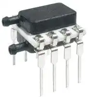


TSCDRRN030PDUCV
PRESSURE SENSOR, 30PSI, RADIAL BARBED
- Manufacturer: HONEYWELL
- Product type: Pressure Transducers
- Port Style: Dual Radial Barbed
- Product Range: TruStability TSC Series
- Sensor Output: Analogue
- Supply Current: 600µA
- Voltage Rating: 5VDC
- Operating Pressure Max: 30psi
- Pressure Measurement Type: Differential
| Delivery and price | |
|---|---|
| Units per pack | 100 |
| Price | 33.36 € |
| Current stock | 10+ |
| Lead time | 30 days |
## TruStability[®] Board Mount Pressure Sensors **TSC Series, Compensated/Unamplified** ±60 mbar to ±10 bar | ±6 kPa to ±1 MPa | ±1 psi to ±150 psi Millivolt Analog Output ## **NSC Series, Uncompensated/Unamplified** ±2.5 mbar to ±10 bar | ±250 Pa to ±1 MPa | ±1 inH2O to ±150 psi Millivolt Analog Output Datasheet ## TruStability[®] Board Mount Pressure Sensors Honeywell’s TruStability[®] TSC Series and NSC Series are piezoresistive silicon pressure sensors offering a ratiometric analog output for reading pressure over the specified full scale pressure span and temperature range. ## **TSC Series:** - Temperature compensated and unamplified. - Compensation makes it easier to integrate the sensor into a system by eliminating the need to calibrate the system over - temperature and also offers reduced part-to-part variation. - Compensated temperature range is 0 °C to 85 °C [-32 °F to 185 °F]. - Operating temperature range is -40 °C to 85 °C [-40 °F to 185 °F]. - Measures differential or gage pressures ## **NSC Series:** - Uncompensated and unamplified. - Allows customers the flexibility of performing their own calibration while still benefiting from the industry-leading stability, - accuracy, and repeatability that the Honeywell TruStability[®] Pressure Sensors provide. - Operates as specified from -40 °C to 85 °C [-40 °F to 185 °F]. - Measures absolute, differential or gage pressures. The absolute versions have an internal vacuum reference and an output value proportional to absolute pressure. Differential versions allow measurement of pressure between two pressure ports. Gage versions are referenced to atmospheric pressure and provide an output proportional to pressure variations from atmosphere. The TSC Series and NSC Series sensors are intended for use with non-corrosive, non-ionic gases, such as air. Port 1 can also be used for non-corrosive, non-ionic liquids on sensors rated above 60 mbar | 6 kPa | 1 psi. The TSC and NSC Series offer numerous package styles and mounting options, making it easier for device manufacturers to integrate the product into their applications. These sensors offer infinite resolution on the pressure signal. Frequency response is also typically limited only by the end user’s system. All products are designed and manufactured according to ISO 9001. ## Table of Contents **==> picture [185 x 273] intentionally omitted <==** **----- Start of picture text -----**<br> |||| |---|---|---| |Features and Benefits . . . . . . . . . . . . . . . . . .|3-4| |Potential Applications . . . . . . . . . . . . . . . . . . . . 5| |TSC Series and NSC Series General| |Specifications . . . . . . . . . . . . . . . . . . . . . . . .|6-7| |TSC Series Nomenclature and Order Guide . . 8| |NSC Series Nomenclature and Order Guide . . 9| |TSC Series Pressure Range Specifications| |±60 mbar to ±10 bar|. . . . . . . . . . . . . . . . . . 10| |±6 kPa to ±1 MPa . . . . . . . . . . . . . . . . . . . . .|11| |±1 psi to 150 psi . . . . . . . . . . . . . . . . . . . . . . 12| |NSC Series Pressure Range Specifications| |±2.5 mbar to ±10 bar . . . . . . . . . . . . . . . . . . 13| |±250 Pa to ±1 MPa . . . . . . . . . . . . . . . . . . . . 14| |±1 inH2O to ±150 psi . . . . . . . . . . . . . . . . . . 15| |Available Standard Configurations . . . . . . .16-17| |Dimensional Drawings| |DIP Packages . . . . . . . . . . . . . . . . . . . . .|18-20| |SMT Packages . . . . . . . . . . . . . . . . . . .|21-23| |SIP Packages . . . . . . . . . . . . . . . . . . . . .|24-28| |Pinouts, PCB Layouts, Circuit Examples . . . . 29| |TruStability|[®]|Board Mount Pressure| |Sensors Portfolio Overview . . . . . . . . . . . . . . 30| |Additional Information. . . . . . . . . . . . . . . . . . . 31| **----- End of picture text -----**<br> ## _**What makes our sensors better?**_ - © • Stability and reliability you can count on - © • Industry-leading accuracy down to ±0.15 %FSS BFSL - 5 • Port and housing options simplify integration - © • Wide pressure range from ±2.5 mbar to ±10 bar | ±250 Pa to ±1 MPa | ±1 inH2O to ±150 psi - © • Small package size - © • Low power consumption stability • accuracy • flexibility • small size **2** sensing.honeywell.com ## Features and Benefits ## **INdUSTry-leadINg loNg-Term STabIlITy** Even after long-term use and thermal extremes, these sensors perform substantially better relative to stability than any other pressure sensor available in the industry today: - Minimizes system calibration needs and maximizes system performance. - Helps support system uptime by eliminating the need to service or replace the sensor during its application life. ## **INdUSTry-leadINg aCCUraCy** Extremely tight accuracy down to ±0.15 %FSS BFSL: - Reduces software needed to correct system inaccuracies, minimizing system design time. - Supports system accuracy and warranty requirements. = - _**Minimizes system calibration and design needs; supports system uptime.**_ - 6—St—<“C‘~=*™S ## **INdUSTry-leadINg flexIbIlITy** - Modular, flexible design with numerous package styles, pressure ports, and options simplifies integration into the device manufacturer’s application. - Single side wet media option allows the end customer to use one port of the sensor with condensing humidity or directly with non-corrosive liquid media. - _**Simplifies product integration.**_ - =. ~~[J]~~ ## **INSeNSITIve To moUNTINg orIeNTaTIoN** Allows flexibility of use within the application. ## **Small SIze** Miniature 10 mm x 10 mm [0.39 in x 0.39 in] package is very small when compared to most board mount pressure sensors: - Occupies less area on the PCB. - Typically allows for easy placement on crowded PCBs or in small devices. ## **repeaTabIlITy** Provides **excellent repeatability, high accuracy and reliability** under many demanding conditions. ## **SUpporTS leaN maNUfaCTUrINg** - J-STD-020-D MSL 1 unlimited shelf life after packaging is opened. - System can be calibrated within one hour after reflow solder. - Compatible with modern lead-free and no-clean solder processes. **3** sensing.honeywell.com Features and Benefits ## **exTremely low power CoNSUmpTIoN** - Operating supply voltage as low as 1.5 Vdc. - Reduces power consumption, provides extended battery life, and promotes energy efficiency. ## **abSolUTe, dIffereNTIal aNd gage TypeS** - Provides flexibility of use within the application. - Absolute type on NSC Series only. ## **preSSUre raNgeS from ±2.5 mbar To ±10 bar | ±250 pa To ±1 mpa | ±1 IN H2o To ±150 pSI** Optimizes the customer’s system performance by maximizing pressure resolution with more available pressure ranges. ## **roHS aNd ISo9001 ComplIaNCe** **4** sensing.honeywell.com ## Potential Applications ## **medICal** - **NebUlIzerS** - **SpIromeTerS** - **paTIeNT moNITorINg eQUIpmeNT** - **THerapeUTIC HoSpITal bedS** - **HoSpITal gaS SUpply** - **oxygeN CoNCeNTraTorS** - **blood aNalySIS** - **gaS CHromaTograpHy** - **aNalyTICal INSTrUmeNTS** ## **INdUSTrIal** - **valveS** - **pUmpS** - **aCTUaTorS** - **HvaC TraNSmITTerS** - **aUTomaTed pNeUmaTIC aSSembly eQUIpmeNT** - **pNeUmaTIC operaTor CoNTrol SySTemS** - **INdUSTrIal gaS SUpply** - **baromeTry** - **gaS CHromaTograpHy** - **aNalyTICal INSTrUmeNT SamplINg SySTemS** **5** sensing.honeywell.com ## TSC Series and NSC Series General Specifications **Table 1. absolute maximum ratings[1]** **==> picture [542 x 122] intentionally omitted <==** **----- Start of picture text -----**<br> Characteristic min. max. Unit<br>Supply voltage (Vsupply) [2] :<br> pressure ranges >60 mbar | 6 kPa | 1 psi -12.0 12.0 Vdc<br> pressure ranges <40 mbar | 4 kPa | 20 inH2O 0 7<br>Storage temperature -40 [-40] 85 [185] °C [°F]<br>Soldering time and temperature:<br> lead solder temperature (SIP, DIP) 4 s max. at 250 °C [482 °F]<br> peak reflow temperature (SMT) 15 s max. at 250 °C [482 °F]<br>**----- End of picture text -----**<br> 1Absolute maximum ratings are the extreme limits the device will withstand without damage. 2Incorrect application of supply voltage or ground to the wrong pin may cause electrical failure. **Table 2. operating Specifications** **==> picture [542 x 176] intentionally omitted <==** **----- Start of picture text -----**<br> Characteristic min. Typ. max. Unit<br>Supply voltage (Vsupply): [1, 2]<br> pressure ranges >60 mbar | 6 kPa | 1 psi 1.5 5.0 12.0 Vdc<br> pressure ranges <40 mbar | 4 kPa | 20 H2O 2.7 5.0 6.5<br>Supply current (at 5.0 Vdc supply)<br> TSC Series — 0.6 1 mA<br> NSC Series — 1.5 2.2<br>—<br>Operating temperature range [3] -40 [-40] 85 [185] °C [°F]<br>—<br>Compensated temperature range [4] 0 [32] 85 [185] °C [°F]<br>Startup time — — 5 ms<br>TSC Series output resistance — 2.5 — kOhm<br>**----- End of picture text -----**<br> 1Ratiometricity of the sensor (the ability of the device output to scale to the supply voltage) is achieved within the specified operating voltage. 2Incorrect application of supply voltage or ground to the wrong pin may cause electrical failure. 3Operating temperature range: The temperature range over which the sensor will produce an output proportional to pressure. 4Compensated temperature range: The temperature range over which the sensor will produce an output proportional to pressure within the specified performance limits. **Table 3. environmental Specifications** **==> picture [542 x 110] intentionally omitted <==** **----- Start of picture text -----**<br> Characteristic parameter<br>Humidity 0% to 95% RH, non-condensing<br>Vibration MIL-STD-202F, Method 214A, Condition 1E (15 g, 10 Hz to 2 kHz)<br>Shock MIL-STD-202F, Method 213B, Condition F (100 g, 6 ms duration)<br>Life [1] 1 million pressure cycles minimum<br>Solder reflow J-STD-020-D MSL1 (unlimited shelf life when stored at less than 30 °C and 85 %RH)<br>**----- End of picture text -----**<br> 1Life may vary depending on the specific application in which the sensor is utilized. **6** sensing.honeywell.com ## TSC Series and NSC Series General Specifications ## **Table 4. wetted materials[1]** **==> picture [542 x 92] intentionally omitted <==** **----- Start of picture text -----**<br> Component port 1 (pressure port) port 2 (reference port)<br>Ports and covers high temperature polyamide high temperature polyamide<br>Substrate alumina ceramic alumina ceramic<br>Adhesives epoxy, RTV epoxy, RTV<br>Electronic components silicon silicon, glass, gold<br>**----- End of picture text -----**<br> - 1Contact Honeywell Customer Service for detailed material information. ## **CAUTION PRODUCT DAMAGE** - Ensure liquid media is applied to Port 1 only; Port 2 is not compatible with liquids. - Ensure liquid media contains no particulates. All TruStability® sensors are dead-ended devices. Particulates can accumulate inside the sensor, causing damage or affecting sensor output. - Recommend that the sensor be positioned with Port 1 facing downwards; any particulates in the system are less likely to enter and settle within the pressure sensor if it is in this position. - Ensure liquid media does not create a residue when dried; build-up inside the sensor may affect sensor output. Rinsing of a dead-ended sensor is difficult and has limited effectiveness for removing residue. - Ensure liquid media are compatible with wetted materials. Non-compatible liquid media will degrade sensor performance and may lead to sensor failure. **Failure to comply with these instructions may result in product damage.** **Table 5. Sensor pressure Types** **==> picture [542 x 74] intentionally omitted <==** **----- Start of picture text -----**<br> pressure Type description<br>Absolute Output is proportional to the difference between applied pressure and a built-in reference to vacuum.<br>Differential Output is proportional to the difference between the pressures applied to each port (Port 1 – Port 2).<br>Gage Output is proportional to the difference between applied pressure and atmospheric (ambient) pressure.<br>**----- End of picture text -----**<br> **7** sensing.honeywell.com ## TSC Series Nomenclature and Order Guide ## **figure 1. TSC Series Nomenclature and order guide[1]** For example, **TSCDNNN150PGUCV** defines a TSC Series TruStability® Pressure Sensor, DIP package, NN pressure port, no special options,150 psi gage pressure range, unamplified, compensated, constant supply voltage. **==> picture [522 x 547] intentionally omitted <==** **----- Start of picture text -----**<br> ||||||||||||||| |---|---|---|---|---|---|---|---|---|---|---|---|---|---| |T S C D N N N|1 5 0 P G U C V| |Series|Supply Voltage| |TSC|Compensated/Unamplified|V|Constant| |Package|Compensation| |D|DIP (Dual Inline Pin)|C|[Compensated]| |M|SMT (Surface Mount Technology)| |S|SIP (Single Inline Pin)|Output Type| |a|=|=|U|[Unamplified]| |Pressure Port| |DIP|SMT|SIP|Pressure Range| |60 mbar to 10 bar|6 kPa to 1 MPa|1 psi to 150 psi| |NN|No ports|NN|No ports|NN|No ports|Differential|Differential|Differential| |>|ais|GP|060MD|±60 mbar|006KD|±6 kPa|001PD|±1 psi| |AA|Dual axialbarbed ports,|100MD|±100 mbar|010KD|±10 kPa|005PD|±5 psi| |opposite sides|160MD|±160 mbar|016KD|±16 kPa|015PD|±15 psi| |ii|=e|we|So|250MD|±250 mbar|025KD|±25 kPa|030PD|±30 psi| |AN|Single axial barbed port|AN|Single axial barbed port|AN|Single axial barbed port|400MD|±400 mbar|040KD|±40 kPa|060PD|±60 psi| |||600MD|±600 mbar|060KD|±60 kPa|100PD|±100 psi|SC| |LN|Single axial barbless port|LN|Single axial barbless port|LN|Single axial barbless port|001BD1.6BD|±1 bar±1.6 bar|100KD160KD|±100 kPa±160 kPa|150PD|±150 psi| |a|=)|Sep|——--—|2.5BD|SS|±2.5 bar|250KD|ee——-—|±250 kPa| |Fastener| |mount, dual|004BD|±4 bar|400KD|±400 kPa| |FF|axial barbed| |ports, opposite|006BD|±6 bar|600KD|±600 kPa| |sides| |—o——t—=éid|&|SS|010BD|±10 bar|001GD|±1 MPa|aaa| |Fastener| |FN|mount, single axial barbed|Gage|Gage|Gage| |a|a|port|=|OO|060MG|0 mbar to 60 mbar|006KG|0 kPa to 6 kPa|001PG|0 psi to 1 psi| |I|I|GN|Ribbedfastener mount,single axialbarbed port|008B|=|SS|100MG160MG|0 mbar to 100 mbar0 mbar to 160 mbar|oo|010KG016KG|0 0 kPa kPa to 10 to 16 kPakPa|005PG015PG|0 psi to 5 psi0 psi to 15 psi| |250MG|0 mbar to 250 mbar|025KG|0 kPa to 25 kPa|030PG|0 psi to 30 psi| |Fastener| |NB|mount, dual axial ports, same side|400MG600MG|0 bar to 400 mbar0 bar to 600 mbar|040KG060KG|0 0 kPakPa to 40 to 60 kPakPa|060PG100PG|0 psi to 60 psi0 psi to 100 psi| |i|.|Ol|001BG|0 bar to 1 bar|100KG|0 kPa to 100 kPa|150PG|0 psi to 150 psi|CC| |RN|Single radialbarbed port|RN|Single radialbarbed port|RN|Single radialbarbed port|1.6BG|0 bar to 1.6 bar|160KG|0 kPa to 160 kPa| |2.5BG|0 bar to 2.5 bar|250KG|0 kPa to 250 kPa| |Dual radial|>|Dual radial|Dual radial|TP|——|004BG|0 bar to 4 bar|400KG|Cd|0 kPa to 400 kPa| |RR|same sidebarbed ports,|RR|barbed ports,same side|RR|same sidebarbed ports,|006BG|0 bar to 6 bar|600KG|0 kPa to 600 kPa| |ll|ia|Se|010BG|0 bar to 10 bar|001GG|0 kPa to 1 MPa| |Dual radial|Dual radial|Dual radial| |DR|barbed ports,|DR|barbed ports,|DR|barbed ports,| |opposite sides|opposite sides|opposite sides| |tit|&|yr| |JN|Single radialbarbless port|JN|Single radialbarbless port|JN|Single radialbarbless port| |Wt|a|Via| |Dual radial|Dual radial|Dual radial| |JJ|same sidebarbless ports,|JJ|same sidebarbless ports,|JJ|barbless ports,same side| |a|ae|Fastener|a| |mount, dual| |HH|radial barbed| |ports, same| |—|—|side|5-5| |Fastener| |HN|mount, singleradial barbed| |port| |=|=| |Manifold| |MN|mount, outer| |diameter seal| |Manifold| |SN|mount, innerdiameter seal| **----- End of picture text -----**<br> ## **Options** **N**[No special options] 1See Table 5 for an explanation of sensor pressure types. **8** sensing.honeywell.com ## NSC Series Nomenclature and Order Guide ## **figure 2. NSC Series Nomenclature and order guide[1]** For example, **NSCDNNN150PGUNV** defines an NSC Series TruStability® Pressure Sensor, DIP package, NN pressure port, no special options,150 psi gage pressure range, unamplified, uncompensated, constant supply voltage. **N S C D N N N 1 5 0 P G U N V** |**Series**<br>**Package**<br>**008B**<br>**Pressure Port**<br>DIP<br>**NSC **Uncompensated/Unamplified<br>SMT<br>**NN**<br>**AA**<br>Dual axial<br>barbed ports,<br>opposite sides<br>SIP<br>**AN**<br>**LN**<br>**FF**<br>Fastener<br>mount, dual<br>axial barbed<br>ports, opposite<br>sides<br>**FN**<br>Fastener<br>mount, single<br>axial barbed<br>port<br>**GN**<br>Ribbed<br>fastener mount,<br>single axial<br>barbed port<br>**NB**<br>Fastener<br>mount, dual<br>axial ports,<br>same side<br>Single radial<br>barbed port<br>**RN**<br>**HH**<br>Fastener<br>mount, dual<br>radial barbed<br>ports, same<br>side<br>**HN**<br>Fastener<br>mount, single<br>radial barbed<br>port<br>**MN**<br>Manifold<br>mount, outer<br>diameter seal<br>Single axial<br>barbed port<br>Single axial<br>barbless port<br>No ports<br>**NN**<br>**AN**<br>**LN**<br>Single radial<br>barbed port<br>Dual radial<br>barbed ports,<br>same side<br>Dual radial<br>barbed ports,<br>opposite sides<br>**RN**<br>**RR**<br>**DR**<br>Single axial<br>barbed port<br>Single axial<br>barbless port<br>No ports<br>**NN**<br>**AN**<br>**LN**<br>Single radial<br>barbed port<br>Dual radial<br>barbed ports,<br>same side<br>Dual radial<br>barbed ports,<br>opposite sides<br>**RN**<br>**RR**<br>**DR**<br>Single axial<br>barbed port<br>Single axial<br>barbless port<br>No ports<br>**SN**<br>Manifold<br>mount, inner<br>diameter seal<br>Dual radial<br>barbed ports,<br>opposite sides<br>**DR**<br>Dual radial<br>barbed ports,<br>same side<br>**RR**<br>Single radial<br>barbless port<br>Dual radial<br>barbless ports,<br>same side<br>**JN**<br>**JJ**<br>Single radial<br>barbless port<br>Dual radial<br>barbless ports,<br>same side<br>**JN**<br>**JJ**<br>Dual radial<br>barbless ports,<br>same side<br>**JJ**<br>Single radial<br>barbless port<br>**JN**<br>**D** DIP (Dual Inline Pin)<br>**M**SMT (Surface Mount Technology)<br>**S**SIP (Single Inline Pin)<br>**Pressure Range**<br>1 in H2O to 150 psi<br>2.5 mbar to 10 bar<br>_Absolute_<br>**015PA**<br>**030PA**<br>**060PA**<br>**100PA**<br>**150PA**<br>_Differential_<br>_Absolute_<br>**001BA** <br>**1.6BA**<br>**2.5BA**<br>**004BA**<br>**006BA**<br>**010BA**<br>_Differential_<br>_Gage_<br>**001ND**<br>**002ND**<br>**004ND**<br>**005ND**<br>**010ND**<br>**020ND**<br>**030ND**<br>**001PD**<br>**005PD**<br>**015PD**<br>**030PD**<br>**060PD**<br>**100PD**<br>**150PD**<br>_Gage_<br>**002NG**<br>**004NG**<br>**005NG**<br>**010NG**<br>**020NG**<br>**030NG**<br>**001PG**<br>**005PG**<br>**015PG**<br>**030PG**<br>**060PG**<br>**100PG**<br>**150PG**<br>**2.5MD**<br>**004MD**<br>**006MD**<br>**010MD**<br>**016MD**<br>**025MD**<br>**040MD**<br>**060MD**<br>**100MD**<br>**160MD**<br>**250MD**<br>**400MD**<br>**600MD**<br>**001BD**<br>**1.6BD**<br>**2.5BD**<br>**004BD**<br>**006BD**<br>**010BD**<br>**004MG**<br>**006MG**<br>**010MG**<br>**016MG**<br>**025MG**<br>**040MG**<br>**060MG**<br>**100MG**<br>**160MG**<br>**250MG**<br>**400MG**<br>**600MG**<br>**001BG**<br>**1.6BG**<br>**2.5BG**<br>**004BG**<br>**006BG**<br>**010BG**<br>**N**<br>No special options<br>**Options**<br>**U** Unamplified<br>**V**<br>Constant<br>**Output Type**<br>**Compensation**<br>**Supply Voltage**<br>**N** Uncompensated<br>0 bar to 1 bar<br>0 bar to 1.6 bar<br>0 bar to 2.5 bar<br>0 bar to 4 bar<br>0 bar to 6 bar<br>0 bar to 10 bar<br>±2.5 mbar<br>±4 mbar<br>±6 mbar<br>±10 mbar<br>±16 mbar<br>±25 mbar<br>±40 mbar<br>±60 mbar<br>±100 mbar<br>±160 mbar<br>±250 mbar<br>±400 mbar<br>±600 mbar<br>±1 bar<br>±1.6 bar<br>±2.5 bar<br>±4 bar<br>±6 bar<br>±10 bar<br>0 mbar to 4 mbar<br>0 mbar to 6 mbar<br>0 mbar to 10 mbar<br>0 mbar to 16 mbar<br>0 mbar to 25 mbar<br>0 mbar to 40 mbar<br>0 mbar to 60 mbar<br>0 mbar to 100 mbar<br>0 mbar to 160 mbar<br>0 mbar to 250 mbar<br>0 bar to 400 mbar<br>0 bar to 600 mbar<br>0 bar to 1 bar<br>0 bar to 1.6 bar<br>0 bar to 2.5 bar<br>0 bar to 4 bar<br>0 bar to 6 bar<br>0 bar to 10 bar<br>400 Pa to 1 MPa<br>_Absolute_<br>**100KA** <br>**160KA**<br>**250KA**<br>**400KA**<br>**600KA**<br>**001GA**<br>_Differential_<br>_Gage_<br>**250LD**<br>**400LD**<br>**600LD**<br>**001KD**<br>**1.6KD**<br>**2.5KD**<br>**004KD**<br>**006KD**<br>**010KD**<br>**016KD**<br>**025KD**<br>**040KD**<br>**060KD**<br>**100KD**<br>**160KD**<br>**250KD**<br>**400KD**<br>**600KD**<br>**001GD**<br>**400LG**<br>**600LG**<br>**001KG**<br>**1.6KG**<br>**004KG**<br>**006KG**<br>**010KG**<br>**016KG**<br>**025KG**<br>**040KG**<br>**060KG**<br>**100KG**<br>**160KG**<br>**250KG**<br>**400KG**<br>**600KG**<br>**001GG**<br>0 kPa to 100 kPa<br>0 kPa to 160 kPa<br>0 kPa to 250 kPa<br>0 kPa to 400 kPa<br>0 kPa to 600 kPa<br>0 kPa to 1 MPa<br>±250 Pa<br>±400 Pa<br>±600 Pa<br>±1 kPa<br>±1.6 kPa<br>±2.5 kPa<br>±4 kPa<br>±6 kPa<br>±10 kPa<br>±16 kPa<br>±25 kPa<br>±40 kPa<br>±60 kPa<br>±100 kPa<br>±160 kPa<br>±250 kPa<br>±400 kPa<br>±600 kPa<br>±1 MPa<br>0 Pa to 400 Pa<br>0 Pa to 600 Pa<br>0 kPa to 1 kPa<br>0 kPa to 1.6 kPa<br>0 kPa to 4 kPa<br>0 kPa to 6 kPa<br>0 kPa to 10 kPa<br>0 kPa to 16 kPa<br>0 kPa to 25 kPa<br>0 kPa to 40 kPa<br>0 kPa to 60 kPa<br>0 kPa to 100 kPa<br>0 kPa to 160 kPa<br>0 kPa to 250 kPa<br>0 kPa to 400 kPa<br>0 kPa to 600 kPa<br>0 kPa to 1 MPa<br>0 inH2O to 2 inH2O<br>0 inH2O to 4 inH2O<br>0 inH2O to 5 inH2O<br>0 inH2O to 10 inH2O<br>0 inH2O to 20 inH2O<br>0 inH2O to 30 inH2O<br>0 psi to 1 psi<br>0 psi to 5 psi<br>0 psi to 15 psi<br>0 psi to 30 psi<br>0 psi to 60 psi<br>0 psi to 100 psi<br>0 psi to 150 psi<br>±1 inH2O<br>±2 inH2O<br>±4 inH2O<br>±5 inH2O<br>±10 inH2O<br>±20 inH2O<br>±30 inH2O<br>±1 psi<br>±5 psi<br>±15 psi<br>±30 psi<br>±60 psi<br>±100 psi<br>±150 psi<br>0 psi to 15 psi<br>0 psi to 30 psi<br>0 psi to 60 psi<br>0 psi to 100 psi<br>0 psi to 150 psi<br>~~a~~<br>=~~=~~<br>—<br>|<br>lP<br>———<br>ii<br>ie<br>we<br>~~—a~~nn<br>i<br><8<br>a<br>San<br>a<br>a<br>SS<br>ddl<br>i<br>ae<br>“=<br>OSC<br>pe<br>ie<br>&<br>—<br>Ol<br>fad<br>=]<br>Via<br>———<br>cd<br>=)<br>iP<br>—|<br>if<br>as<br>UP<br>ff<br>cj<br>Vid<br>lS<br>aid<br>te?<br>ad<br>——— <=<br>i<br>ie<br>5-5<br>_—SSE<br>aa<br>—S<br>=<br>——<br>——<br>a<br>|<br>a<br>_——<br>~~_7~~|**U** Unamplified<br>**V**<br>Constant<br>**Output Type**<br>**Compensation**<br>**Supply Voltage**<br>**N** Uncompensated<br>=~~=~~| |---|---| ||=~~=~~| **Options** ~~_7~~ **N** No special options 1See Table 5 for an explanation of sensor pressure types. **9** sensing.honeywell.com ## TSC Series Specifications ## ±60 mbar to ±10 bar **Table 6. TSC Series pressure range Specifications for** ± **60 mbar to** ± **10 bar** **==> picture [542 x 346] intentionally omitted <==** **----- Start of picture text -----**<br> Thermal effect Thermal effect<br>pressure full Scale Span<br>on offset [2] on Span [3]<br>range (mv/v)<br>(%fSS) (%fSS)<br>offset [1]<br>Unit<br>(mv/v)<br>10 °C 0 °C 10 °C 0 °C<br>pmin. pmax. to to to to<br> 50 °C 85 °C 50 °C 85 °C<br>differential<br>060MD -60 60 mbar 872 1370 10,000 ±0.20 ±0.075 2.46 2.60 2.80 ±0.60 ±1.15 ±1.00 ±2.00 ±0.15 ±0.15<br>100MD -100 100 mbar 872 1370 10,000 ±0.20 ±0.075 4.12 4.40 4.66 ±0.35 ±0.70 ±1.00 ±2.00 ±0.10 ±0.10<br>160MD -160 160 mbar 2000 4000 10,000 ±0.15 ±0.12 4.36 4.60 4.92 ±0.80 ±1.65 ±0.75 ±2.00 ±0.10 ±0.10<br>250MD -250 250 mbar 2000 4000 10,000 ±0.15 ±0.12 6.82 7.30 7.70 ±0.55 ±1.05 ±0.75 ±2.00 ±0.10 ±0.10<br>400MD -400 400 mbar 2000 4000 10,000 ±0.15 ±0.12 10.90 11.60 12.30 ±0.35 ±0.65 ±0.75 ±2.00 ±0.10 ±0.10<br>600MD -600 600 mbar 4000 8000 10,000 ±0.15 ±0.075 5.88 16.10 6.36 ±0.40 ±0.85 ±0.50 ±1.25 ±0.10 ±0.10<br>001BD -1 1 bar 4 8 10 ±0.15 ±0.075 9.80 10.20 10.60 ±0.25 ±0.50 ±0.50 ±1.25 ±0.10 ±0.10<br>1.6BD -1.6 1.6 bar 4 8 10 ±0.15 ±0.075 15.68 16.30 16.96 ±0.15 ±0.30 ±0.50 ±1.25 ±0.10 ±0.10<br>2.5BD -2.5 2.5 bar 8 17 10 ±0.15 ±0.075 12.20 12.70 13.18 ±0.20 ±0.40 ±0.50 ±1.50 ±0.10 ±0.10<br>004BD -4 4 bar 10 17 15 ±0.15 ±0.075 11.14 11.60 12.08 ±0.25 ±0.50 ±0.50 ±1.25 ±0.10 ±0.10<br>006BD -6 6 bar 17 17 15 ±0.15 ±0.075 10.16 10.60 11.08 ±0.35 ±0.50 ±0.50 ±1.00 ±0.10 ±0.10<br>010BD -10 10 bar 17 17 15 ±0.15 ±0.075 16.94 17.70 18.44 ±0.20 ±0.3 ±0.5 ±1.00 ±0.10 ±0.10<br>gage<br>060MG 0 60 mbar 872 1370 10,000 ±0.20 ±0.075 1.23 1.30 1.40 ±1.15 ±2.35 ±1.00 ±2.00 ±0.30 ±0.30<br>100MG 0 100 mbar 872 1370 10,000 ±0.20 ±0.075 2.06 2.20 2.33 ±0.70 ±1.40 ±1.00 ±2.00 ±0.20 ±0.20<br>160MG 0 160 mbar 2000 4000 10,000 ±0.15 ±0.12 2.18 2.30 2.46 ±1.65 ±3.30 ±0.75 ±2.00 ±0.20 ±0.20<br>250MG 0 250 mbar 2000 4000 10,000 ±0.15 ±0.12 3.41 3.65 3.85 ±1.05 ±2.10 ±0.75 ±2.00 ±0.15 ±0.15<br>400MG 0 400 mbar 2000 4000 10,000 ±0.15 ±0.12 5.45 5.80 6.15 ±0.65 ±1.30 ±0.75 ±2.00 ±0.10 ±0.10<br>600MG 0 600 mbar 4000 8000 10,000 ±0.15 ±0.075 2.94 3.05 3.18 ±0.85 ±1.65 ±0.50 ±1.25 ±0.15 ±0.15<br>001BG 0 1 bar 4 8 10 ±0.15 ±0.075 4.90 5.10 5.30 ±0.50 ±1.00 ±0.50 ±1.25 ±0.10 ±0.10<br>1.6BG 0 1.6 bar 4 8 10 ±0.15 ±0.075 7.84 8.15 8.48 ±0.30 ±0.65 ±0.50 ±1.25 ±0.10 ±0.10<br>2.5BG 0 2.5 bar 8 17 10 ±0.15 ±0.075 6.10 6.35 6.59 ±0.40 ±0.80 ±0.50 ±1.50 ±0.10 ±0.10<br>004BG 0 4 bar 10 17 15 ±0.15 ±0.075 5.57 5.80 6.04 ±0.50 ±1.00 ±0.50 ±1.25 ±0.10 ±0.10<br>006BG 0 6 bar 17 17 15 ±0.15 ±0.075 5.08 5.30 5.54 ±0.65 ±1.00 ±0.50 ±1.00 ±0.15 ±0.15<br>010BG 0 10 bar 17 17 15 ±0.15 ±0.075 8.47 8.85 9.22 ±0.40 ±0.60 ±0.50 ±1.00 ±0.10 ±0.10<br>4<br>pressure (%fSS) (%fSS) (%fSS)<br>order Code<br>pressure range (see figure 1) over pressure burst pressure Common mode min. Nom. max. 1000 hr, 25 °C<br>pressure accuracy long-Term Stability Thermal Hysteresis<br>**----- End of picture text -----**<br> 1Offset: The output signal obtained when the reference pressure is applied to all available pressure ports. Also known as “null” or “zero”. 2Thermal effect on offset: The deviation in offset due to changes in temperature over the compensated temperature range, relative to offset measured at 25 ºC. 3Thermal effect on span: The deviation in full scale span due to changes in temperature over the compensated temperature range, relative to full scale span measured at 25 ºC. 4Thermal hysteresis: The maximum difference between output readings when the same temperature is reached consecutively, under the same operating conditions, with temperature approaching from opposite directions within the operating temperature range. Validated over the full operating temperature and pressure ranges using a ~5 ºC/minute ramp and 30 minute dwell. Application performance may be affected by the thermal mass of the end user system. **10** sensing.honeywell.com ## TSC Series Specifications ## ±6 kPa to ±1 MPa **Table 7. TSC Series pressure range Specifications for** ± **6 kpa to** ± **1 mpa** **==> picture [542 x 346] intentionally omitted <==** **----- Start of picture text -----**<br> Thermal effect Thermal effect<br>pressure full Scale Span<br>on offset [2] on Span [3]<br>range (mv/v)<br>(%fSS) (%fSS)<br>offset [1]<br>Unit<br>(mv/v)<br>10 °C 0 °C 10 °C 0 °C<br>pmin. pmax. to to to to<br> 50 °C 85 °C 50 °C 85 °C<br>differential<br>006KD -6 6 kPa 87 137 1000 ±0.20 ±0.075 2.46 2.60 2.80 ±0.60 ±1.15 ±1.00 ±2.00 ±0.15 ±0.15<br>010KD -10 10 kPa 87 137 1000 ±0.20 ±0.075 4.12 4.40 4.66 ±0.35 ±0.70 ±1.00 ±2.00 ±0.10 ±0.10<br>016KD -16 16 kPa 200 400 1000 ±0.15 ±0.12 4.36 4.60 4.92 ±0.80 ±1.65 ±0.75 ±2.00 ±0.10 ±0.10<br>025KD -25 25 kPa 200 400 1000 ±0.15 ±0.12 6.82 7.30 7.70 ±0.55 ±1.05 ±0.75 ±2.00 ±0.10 ±0.10<br>040KD -40 40 kPa 200 400 1000 ±0.15 ±0.12 10.90 11.60 12.30 ±0.35 ±0.65 ±0.75 ±2.00 ±0.10 ±0.10<br>060KD -60 60 kPa 400 800 1000 ±0.15 ±0.075 5.88 16.10 6.36 ±0.40 ±0.85 ±0.50 ±1.25 ±0.10 ±0.10<br>100KD -100 100 kPa 400 800 1000 ±0.15 ±0.075 9.80 10.20 10.60 ±0.25 ±0.50 ±0.50 ±1.25 ±0.10 ±0.10<br>160KD -160 160 kPa 400 800 1000 ±0.15 ±0.075 15.68 16.30 16.96 ±0.15 ±0.30 ±0.50 ±1.25 ±0.10 ±0.10<br>250KD -250 250 kPa 800 1700 1000 ±0.15 ±0.075 12.20 12.70 13.18 ±0.20 ±0.40 ±0.50 ±1.50 ±0.10 ±0.10<br>400KD -400 400 kPa 1000 1700 1600 ±0.15 ±0.075 11.14 11.60 12.08 ±0.25 ±0.50 ±0.50 ±1.25 ±0.10 ±0.10<br>600KD -600 600 kPa 1700 1700 1700 ±0.15 ±0.075 10.16 10.60 11.08 ±0.35 ±0.50 ±0.50 ±1.00 ±0.10 ±0.10<br>001GD -1 1 MPa 1.70 1.70 1.7 ±0.15 ±0.075 16.94 17.70 18.44 ±0.20 ±0.30 ±0.50 ±1.00 ±0.10 ±0.10<br>gage<br>006KG 0 6 kPa 87 137 1000 ±0.20 ±0.075 1.23 1.30 1.40 ±1.15 ±2.35 ±1.00 ±2.00 ±0.30 ±0.30<br>010KG 0 10 kPa 87 137 1000 ±0.20 ±0.075 2.06 2.20 2.33 ±0.70 ±1.40 ±1.00 ±2.00 ±0.20 ±0.20<br>016KG 0 16 kPa 200 400 1000 ±0.15 ±0.12 2.18 2.30 2.46 ±1.65 ±3.30 ±0.75 ±2.00 ±0.20 ±0.20<br>025KG 0 25 kPa 200 400 1000 ±0.15 ±0.12 3.41 3.65 3.85 ±1.05 ±2.10 ±0.75 ±2.00 ±0.15 ±0.15<br>040KG 0 40 kPa 200 400 1000 ±0.15 ±0.12 5.45 5.80 6.15 ±0.65 ±1.30 ±0.75 ±2.00 ±0.10 ±0.10<br>060KG 0 60 kPa 400 800 1000 ±0.15 ±0.075 2.94 3.05 3.18 ±0.85 ±1.65 ±0.50 ±1.25 ±0.15 ±0.15<br>100KG 0 100 kPa 400 800 1000 ±0.15 ±0.075 4.90 5.10 5.30 ±0.50 ±1.00 ±0.50 ±1.25 ±0.10 ±0.10<br>160KG 0 160 kPa 400 800 1000 ±0.15 ±0.075 7.84 8.15 8.48 ±0.30 ±0.65 ±0.50 ±1.25 ±0.10 ±0.10<br>250KG 0 250 kPa 800 1700 1000 ±0.15 ±0.075 6.10 6.35 6.59 ±0.40 ±0.80 ±0.50 ±1.50 ±0.10 ±0.10<br>400KG 0 400 kPa 1000 1700 1600 ±0.15 ±0.075 5.57 5.80 6.04 ±0.50 ±1.00 ±0.50 ±1.25 ±0.10 ±0.10<br>600KG 0 600 kPa 1700 1700 1700 ±0.15 ±0.075 5.08 5.30 5.54 ±0.65 ±1.00 ±0.50 ±1.00 ±0.15 ±0.15<br>001GG 0 1 MPa 1.70 1.70 1.7 ±0.15 ±0.075 8.47 8.85 9.22 ±0.40 ±0.60 ±0.50 ±1.00 ±0.10 ±0.10<br>4<br>pressure (%fSS) (%fSS) (%fSS)<br>order Code<br>pressure range (see figure 1) over pressure burst pressure Common mode min. Nom. max. 1000 hr, 25 °C<br>pressure accuracy long-Term Stability Thermal Hysteresis<br>**----- End of picture text -----**<br> 1Offset: The output signal obtained when the reference pressure is applied to all available pressure ports. Also known as “null” or “zero”. 2Thermal effect on offset: The deviation in offset due to changes in temperature over the compensated temperature range, relative to offset measured at 25 ºC. 3Thermal effect on span: The deviation in full scale span due to changes in temperature over the compensated temperature range, relative to full scale span measured at 25 ºC. 4Thermal hysteresis: The maximum difference between output readings when the same temperature is reached consecutively, under the same operating conditions, with temperature approaching from opposite directions within the operating temperature range. Validated over the full operating temperature and pressure ranges using a ~5 ºC/minute ramp and 30 minute dwell. Application performance may be affected by the thermal mass of the end user system. **11** sensing.honeywell.com ## TSC Series Specifications ## ±1 psi to ±150 psi **Table 8. TSC Series pressure range Specifications for** ± **1 psi to** ± **150 psi** **==> picture [542 x 243] intentionally omitted <==** **----- Start of picture text -----**<br> Thermal effect Thermal effect<br>pressure full Scale Span<br>on offset [2] on Span [3]<br>range (mv/v)<br>offset [1] (%fSS/ºC) (%fSS/ºC)<br>Unit<br>(mv/v)<br>10 °C 0 °C 10 °C 0 °C<br>pmin. pmax. to to to to<br> 50 °C 85 °C 50 °C 85 °C<br>differential<br>001PD -1 1 psi 12.5 20 145 ±0.20 ±0.075 2.84 3.00 3.22 ±0.50 ±1.00 ±1.00 ±2.00 ±0.15 ±0.15<br>005PD -5 5 psi 30 60 145 ±0.15 ±0.12 9.40 10.00 10.60 ±0.40 ±0.75 ±0.75 ±2.00 ±0.10 ±0.10<br>015PD -15 15 psi 60 115 145 ±0.15 ±0.075 10.12 10.50 10.98 ±0.25 ±0.50 ±0.50 ±1.25 ±0.10 ±0.10<br>030PD -30 30 psi 115 245 145 ±0.15 ±0.075 10.10 10.50 10.90 ±0.25 ±0.50 ±0.50 ±1.50 ±0.10 ±0.10<br>060PD -60 60 psi 145 245 230 ±0.15 ±0.075 11.52 12.00 12.48 ±0.25 ±0.50 ±0.50 ±1.25 ±0.10 ±0.10<br>100PD -100 100 psi 245 245 245 ±0.15 ±0.075 11.66 12.00 12.72 ±0.30 ±0.45 ±0.50 ±1.00 ±0.10 ±0.10<br>150PD -150 150 psi 245 245 245 ±0.15 ±0.075 17.50 18.30 19.08 ±0.20 ±0.30 ±0.50 ±1.00 ±0.10 ±0.10<br>gage<br>001PG 0 1 psi 12.7 20 145 ±0.20 ±0.075 1.42 1.50 1.61 ±1.00 ±2.05 ±1.00 ±2.00 ±0.25 ±0.25<br>005PG 0 5 psi 30 60 145 ±0.15 ±0.12 4.70 5.00 5.30 ±0.75 ±1.50 ±0.75 ±2.00 ±0.10 ±0.10<br>015PG 0 15 psi 60 115 145 ±0.15 ±0.075 5.06 5.25 5.49 ±0.50 ±0.95 ±0.50 ±1.25 ±0.10 ±0.10<br>030PG 0 30 psi 115 245 145 ±0.15 ±0.075 5.05 5.25 5.45 ±0.50 ±0.95 ±0.50 ±1.50 ±0.10 ±0.10<br>060PG 0 60 psi 145 245 230 ±0.15 ±0.075 5.76 6.00 6.24 ±0.50 ±0.95 ±0.50 ±1.25 ±0.10 ±0.10<br>100PG 0 100 psi 245 245 245 ±0.15 ±0.075 5.83 6.10 6.36 ±0.60 ±0.85 ±0.50 ±1.00 ±0.10 ±0.10<br>150PG 0 150 psi 245 245 245 ±0.15 ±0.075 8.75 9.15 9.54 ±0.40 ±0.60 ±0.50 ±1.00 ±0.10 ±0.10<br>4<br>pressure (%fSS) (%fSS) (%fSS)<br>order Code<br>pressure range (see figure 1) over pressure burst pressure Common mode min. Nom. max. 1000 hr, 25 °C<br>pressure accuracy long-Term Stability Thermal Hysteresis<br>**----- End of picture text -----**<br> 1Offset: The output signal obtained when the reference pressure is applied to all available pressure ports. Also known as “null” or “zero”. 2Thermal Effect on Offset: The deviation in offset due to changes in temperature over the compensated temperature range, relative to offset measured at 25 ºC. 3Thermal Effect on Span: The deviation in full scale span due to changes in temperature over the compensated temperature range, relative to full scale span measured at 25 ºC. 4Thermal Hysteresis: The maximum difference between output readings when the same temperature is reached consecutively, under the same operating conditions, with temperature approaching from opposite directions within the operating temperature range. Validated over the full operating temperature and pressure ranges using a ~5 ºC/minute ramp and 30 minute dwell. Application performance may be affected by the thermal mass of the end user system. ## **figure 3. TSC Series Typical Temperature performance** The graph below indicates typical error multipliers for Thermal Effect on Offset (TEO) and Thermal Effect on Span (TES) outside the Compensated Temperature Range. See Tables 6-8 for details of the specified maximum errors within the Compensated Temperature Range. **==> picture [521 x 173] intentionally omitted <==** **----- Start of picture text -----**<br> 4<br>3<br>2<br>1<br>Operating Temperature Range<br>0<br>Compensated Temperature Range<br>-1<br>-2<br>-3<br>-4<br>-40 [-40] -20 [-4] 0 [32] 10 [50] 50 [122] 85 [185] 125 [257]<br>Temperature (°C [°F])<br>for TEO and TES<br>Typical Error Multiplier<br>**----- End of picture text -----**<br> **12** sensing.honeywell.com ## NSC Series Specifications ±2.5 mbar to ±10 bar **Table 9. NSC Series pressure range Specifications for** ± **2.5 mbar to** ± **10 bar** **==> picture [543 x 548] intentionally omitted <==** **----- Start of picture text -----**<br> full Scale Input TCr [4] TCr [4]<br>offset [1] TCo [2] TCS [2]<br>Span resistance [3] (-40 ºC to 25 ºC) (25 ºC to 85 ºC)<br> (mv/v) (%fSS/25 ºC) (%fSS/25 ºC)<br>(mv/v) (kohm) (ppm/°C) (ppm/°C)<br>absolute<br>001BA 0 1 bar - 2 4.1 N/A -6.0 0.0 6.0 10.0 14.5 19.0 -3.8 0.0 3.8 -7.5 -5 -3.0 2.6 3.5 4.4 500 1000 1500 1500 2000 2500 ±0.25 ±0.25<br>1.6BA 0 1.6 bar - 4.1 8 N/A -6.0 0.0 6.0 7.7 11.4 15.2 -4.9 0.0 4.9 -7.5 -5 -3.0 2.6 3.5 4.4 500 1000 1500 1500 2000 2500 ±0.25 ±0.25<br>2.5BA 0 2.5 bar - 4.1 8 N/A -6.0 0.0 6.0 12.0 17.9 23.8 -3.1 0.0 3.1 -7.5 -5 -3.0 2.6 3.5 4.4 500 1000 1500 1500 2000 2500 ±0.20 ±0.25<br>004BA 0 4 bar - 8 17 N/A -6.0 0 6.0 10.3 14.7 19.0 -3.6 0.0 3.6 -7.5 -5 -3.0 2.6 3.5 4.4 500 1000 1500 1500 2000 2500 ±0.25 ±0.25<br>006BA 0 6 bar - 17 17 N/A -6.0 0.0 6.0 7.9 11.0 14.0 -4.8 0.0 4.8 -7.5 -5 -3.0 2.6 3.5 4.4 500 1000 1500 1500 2000 2500 ±0.25 ±0.25<br>010BA 0 10 bar - 17 17 N/A -6.0 0.0 6.0 13.2 18.3 23.4 -2.9 0.0 2.9 -7.5 -5 -3.0 2.6 3.5 4.4 500 1000 1500 1500 2000 2500 ±0.20 ±0.25<br>differential<br>2.5MD -2.5 2.5 mbar 335 675 1000 3450 -24 -4 16 10.5 15.8 21. -3.0 5.1 13.3 -8.9 -6 -3.8 2.5 3.3 4 1800 2175 2550 1300 1525 1750 ±0.50 ±0.25<br>004MD -4 4 mbar 335 675 1000 3450 -24 -4 16 16.9 25.3 33.7 -1.9 3.2 8.3 -8.9 -6 -3.8 2.5 3.3 4 1800 2175 2550 1300 1525 1750 ±0.30 ±0.25<br>006MD -6 6 mbar 335 675 1000 3450 -24 -4 16 25.3 37.9 50.6 -1.2 2.1 5.5 -8.9 -6 -3.8 2.5 3.3 4 1800 2175 2550 1300 1525 1750 ±0.20 ±0.25<br>010MD -10 10 mbar 375 745 1250 5450 -24 -4 16 35.2 52.6 70.0 -1.9 1.8 5.5 -8.9 -6 -3.8 2.5 3.3 4 1800 2175 2550 1300 1525 1750 ±0.25 ±0.25<br>016MD -16 16 mbar 435 850 1350 10,450 -8.0 -2.0 4.0 6.7 10.1 13.5 -3.1 0.8 4.7 -8.9 -6 -3.8 2.5 3.3 4 1800 2175 2550 1300 1525 1750 ±0.40 ±0.25<br>025MD -25 25 mbar 435 850 1350 10,450 -8.0 -2.0 4.0 10.5 15.8 21.1 -2.0 0.5 3.0 -8.9 -6 -3.8 2.5 3.3 4 1800 2175 2550 1300 1525 1750 ±0.25 ±0.25<br>040MD -40 40 mbar 435 850 1380 10,450 -8.5 -2.5 3.5 5.2 7.5 9.9 -1.9 0.9 1.9 -6.3 -5 -3.8 4 5 6 1200 1700 2550 2220 2700 3200 ±0.30 ±0.25<br>060MD -60 60 mbar 435 850 1380 10,450 -8.5 -2.5 3.5 7.8 11.3 14.8 -1.3 0.6 1.3 -6.3 -5 -3.8 4 5 6 1200 1700 2200 2220 2700 3200 ±0.20 ±0.25<br>100MD -100 100 mbar 435 850 1380 10,450 -8.5 -2.5 3.5 13.1 18.9 24.7 -0.8 0.3 0.8 -6.3 -5 -3.8 4 5 6 1200 1700 2200 2220 2700 3200 ±0.15 ±0.25<br>160MD -160 160 mbar 435 850 1380 10,450 -8.5 -2.5 3.5 20.9 30.2 39.5 -0.5 0.2 0.5 -6.3 -5 -3.8 4 5 6 1200 1700 2200 2220 2700 3200 ±0.15 ±0.25<br>250MD -250 250 mbar - 1380 2760 10,000 -8.5 -2.5 3.5 14.5 21.8 29.0 -0.7 0.3 0.7 -6.3 -5 -3.8 4 5 6 1200 1700 2200 2220 2700 3200 ±0.25 ±0.25<br>400MD -400 400 mbar - 1380 2760 10,000 -8.5 -2.5 3.5 23.2 34.8 46.4 -0.4 0.2 0.4 -6.3 -5 -3.8 4 5 6 1200 1700 2200 2220 2700 3200 ±0.15 ±0.25<br>600MD -600 600 mbar - 2060 4100 10,000 -7.0 -0.85 5.3 12.0 18.0 24.0 -0.8 0.5 0.8 -6.0 -5 -3.8 2.4 3 5.5 1200 1700 2200 2220 2700 3200 ±0.20 ±0.25<br>001BD -1 1 bar - 2 4.1 10 -7.0 -0.85 5.3 20.0 30.0 40.0 -0.6 0.3 0.5 -6.0 -5 -3.8 2.4 3 5.5 1200 1700 2200 2220 2700 3200 ±0.15 ±0.25<br>1.6BD -1.6 1.6 bar - 4.1 8 10 -7.0 -0.85 5.3 24.0 32.0 40.0 -0.4 0.3 0.4 -6.0 -5 -3.8 2.4 3 5.5 1200 1700 2200 2220 2700 3200 ±0.15 ±0.25<br>2.5BD -2.5 2.5 bar - 4.1 8 10 -7.0 -0.85 5.3 37.5 50.0 62.5 -0.3 0.2 0.3 -6.0 -5 -3.8 2.4 3 5.5 1200 1700 2200 2220 2700 3200 ±0.10 ±0.25<br>004BD -4 4 bar - 8 17 17 -7.0 -0.85 5.3 33.6 40.0 46.4 -0.3 0.2 0.3 -6.0 -5 -3.8 2.4 3 5.5 1200 1700 2200 2220 2700 3200 ±0.15 ±0.25<br>006BD -6 6 bar - 17 17 17 -7.0 -0.85 5.3 25.2 30.0 34.8 -0.4 0.3 0.4 -6.0 -5 -3.8 2.4 3 5.5 1200 1700 2200 2220 2700 3200 ±0.15 ±0.25<br>010BD -10 10 bar - 17 17 17 -7.0 -0.85 5.3 42.0 50.0 58.0 -0.2 0.1 0.2 -6.0 -5 -3.8 2.4 3 5.5 1200 1700 2200 2220 2700 3200 ±0.10 ±0.25<br>gage<br>004MG 0 4 mbar 335 675 1000 3440 -24 -4 16 8.4 12.6 16.9 -3.7 6.4 16.6 -8.9 -6 -3.8 2.5 3.3 4 1800 2175 2550 1300 1525 1750 ±0.50 ±0.25<br>006MG 0 6 mbar 335 675 1000 3440 -24 -4 16 12.6 19.0 25.3 -2.5 4.3 11.0 -8.9 -6 -3.8 2.5 3.3 4 1800 2175 2550 1300 1525 1750 ±0.40 ±0.25<br>010MG 0 10 mbar 375 745 1245 5440 -24 -4 16 17.6 26.3 35.0 -3.8 3.6 11.0 -8.9 -6 -3.8 2.5 3.3 4 1800 2175 2550 1300 1525 1750 ±0.50 ±0.25<br>016MG 0 16 mbar 435 850 1350 10,440 -8.5 -2.0 4.0 3.4 5.1 6.7 -6.2 1.6 9.3 -8.9 -6 -3.8 2.5 3.3 4 1800 2175 2550 1300 1525 1750 ±0.50 ±0.25<br>025MG 0 25 mbar 435 850 1350 10,440 -8.5 -2.0 4.0 5.3 7.9 10.5 -4.0 1.0 6.0 -8.9 -6 -3.8 2.5 3.3 4 1800 2175 2550 1300 1525 1750 ±0.50 ±0.25<br>040MG 0 40 mbar 435 850 1380 10,440 -8.5 -2.5 3.5 2.6 3.8 4.9 -3.8 1.7 3.8 -6.3 -5 -3.8 4 5 6 1200 1700 2200 2220 2700 3200 ±0.50 ±0.25<br>060MG 0 60 mbar 435 850 1380 10,440 -8.5 -2.5 3.5 3.9 5.7 7.4 -2.6 1.1 2.6 -6.3 -5 -3.8 4 5 6 1200 1700 2200 2220 2700 3200 ±0.40 ±0.25<br>100MG 0 100 mbar 435 850 1380 10,440 -8.5 -2.5 3.5 6.5 9.4 12.3 -1.5 0.7 1.5 -6.3 -5 -3.8 4 5 6 1200 1700 2200 2220 2700 3200 ±0.25 ±0.25<br>160MG 0 160 mbar 435 850 1380 10,440 -8.5 -2.5 3.5 10.4 15.1 19.7 -1.0 0.4 1.0 -6.3 -5 -3.8 4 5 6 1200 1700 2200 2220 2700 3200 ±0.15 ±0.25<br>250MG 0 250 mbar - 1380 2760 10,000 -8.5 -2.5 3.5 7.3 10.9 14.5 -1.4 0.6 1.4 -6.3 -5 -3.8 4 5 6 1200 1700 2200 2220 2700 3200 ±0.35 ±0.25<br>400MG 0 400 mbar - 1380 2760 10,000 -8.5 -2.5 3.5 11.6 17.4 23.2 -0.9 0.3 0.9 -6.3 -5 -3.8 4 5 6 1200 1700 2200 2220 2700 3200 ±0.30 ±0.25<br>600MG 0 600 mbar - 2060 4100 10,000 -7.0 -0.85 5.3 6.0 9.0 12.0 -1.7 1.0 1.7 -6.0 -5 -3.8 2.4 3 5.5 1200 1700 2200 2220 2700 3200 ±0.25 ±0.25<br>001BG 0 1 bar - 2 4.1 10 -7.0 -0.85 5.3 10.0 15.0 20.0 -1.0 0.6 1.0 -6.0 -5 -3.8 2.4 3 5.5 1200 1700 2200 2220 2700 3200 ±0.25 ±0.25<br>1.6BG 0 1.6 bar - 4.1 8 10 -7.0 -0.85 5.3 12.0 16.0 20.0 -0.8 0.5 0.8 -6.0 -5 -3.8 2.4 3 5.5 1200 1700 2200 2220 2700 3200 ±0.25 ±0.25<br>2.5BG 0 2.5 bar - 4.1 8 10 -7.0 -0.85 5.3 18.8 25.0 31.3 -0.6 0.3 0.5 -6.0 -5 -3.8 2.4 3 5.5 1200 1700 2200 2220 2700 3200 ±0.20 ±0.25<br>004BG 0 4 bar - 8 17 17 -7.0 -0.85 5.3 16.8 20.0 23.2 -0.6 0.4 0.6 -6.0 -5 -3.8 2.4 3 5.5 1200 1700 2200 2220 2700 3200 ±0.25 ±0.25<br>006BG 0 6 bar - 17 17 17 -7.0 -0.85 5.3 12.6 15.0 17.4 -0.8 0.6 0.8 -6.0 -6 -3.8 2.4 3 5.5 1200 1700 2200 2220 2700 3200 ±0.25 ±0.25<br>010BG 0 10 bar - 17 17 17 -7.0 -0.85 5.3 21.0 25.0 29.0 -0.5 0.4 0.5 -6.0 -6 -3.8 2.4 3 5.5 1200 1700 2200 2220 2700 3200 ±0.20 ±0.25<br>range<br>pressure<br>Unit<br>order Code pressure accuracy (%fSS)<br>pressure range (see figure 2) pmin. pmax. working pressure over pressure burst pressure Common mode min. Nom. max. min. Nom. max. min. Nom. max. min. Nom. max. min. Nom. max. min. Nom. max. min. Nom. max. long-Term Stability 1000 hr, 25 °C(%fSS)<br>**----- End of picture text -----**<br> 1Offset: The output signal obtained when the reference pressure is applied to all available pressure ports. Also known as “null” or “zero”. 2TCO (Thermal Coefficient of Offset): The deviation in offset due to changes in temperature over the compensated temeprature range, relative to offset measured at 25 ºC. 3TCS (Thermal Coefficient of Span): The deviation in full scale span due to changes in temperature over the compensated temeprature range, relative to full scale span measured at 25 ºC. 4TCR (Thermal Coefficient of Resistance): The deviation in input resistance due to changes in temperature over the specified temperature range, relative to input resistance measured at 25 ºC. **13** sensing.honeywell.com ## NSC Series Specifications ±250 Pa to ±1 Mpa **Table 10. NSC Series pressure range Specifications for ±250 pa to** ± **1 mpa** **==> picture [542 x 537] intentionally omitted <==** **----- Start of picture text -----**<br> full Scale Input TCr [4] TCr [4]<br>offset [1] TCo [2] TCS [3]<br>Span resistance [3] (-40 ºC to 25 ºC) (25 ºC to 85 ºC)<br> (mv/v) (%fSS/25 ºC) (%fSS/25 ºC)<br>(mv/v) (kohm) (ppm/°C) (ppm/°C)<br>absolute<br>100KA 0 100 kPa - 200 400 N/A -6 0 6 10.0 14.5 19.0 -3.8 0.0 3.8 -7.5 -5 -3.0 2.6 3.5 4.4 500 1000 1500 1500 2000 2500 ±0.25 ±0.25<br>160KA 0 160 kPa - 400 800 N/A -6 0 6 7.7 11.4 15.2 -4.9 0.0 4.9 -7.5 -5 -3.0 2.6 3.5 4.4 500 1000 1500 1500 2000 2500 ±0.25 ±0.25<br>250KA 0 250 kPa - 400 800 N/A -6 0 6 12.0 17.9 23.8 -3.1 0.0 3.1 -7.5 -5 -3.0 2.6 3.5 4.4 500 1000 1500 1500 2000 2500 ±0.20 ±0.25<br>400KA 0 400 kPa - 800 1700 N/A -6 0 6 10.3 14.7 19.0 -3.6 0.0 3.6 -7.5 -5 -3.0 2.6 3.5 4.4 500 1000 1500 1500 2000 2500 ±0.25 ±0.25<br>600KA 0 600 kPa - 1700 1700 N/A -6 0 6 7.9 11.0 14.0 -4.8 0.0 4.8 -7.5 -5 -3.0 2.6 3.5 4.4 500 1000 1500 1500 2000 2500 ±0.25 ±0.25<br>001GA 0 1 MPa - 1.7 1.7 N/A -6 0 6 13.2 18.3 23.4 -2.9 0.0 2.9 -7.5 -5 -3.0 2.6 3.5 4.4 500 1000 1500 1500 2000 2500 ±0.20 ±0.25<br>differential<br>250LD -250 250 Pa 33,500 67,500 100,000 345,000 -24 -4 16 10.5 15.8 21.1 -3.0 5.1 13.3 -8.9 -6 -3.8 2.5 3.3 4 1800 2175 2550 1300 1525 1750 ±0.50 ±0.25<br>400LD -400 400 Pa 33,500 67,500 100,000 345,000 -24 -4 16 16.9 25.3 33.7 -1.9 3.2 8.3 -8.9 -6 -3.8 2.5 3.3 4 1800 2175 2550 1300 1525 1750 ±0.30 ±0.25<br>600LD -600 600 Pa 33,500 67,500 100,000 345,000 -24 -4 16 25.3 37.9 50.6 -1.2 2.1 5.5 -8.9 -6 -3.8 2.5 3.3 4 1800 2175 2550 1300 1525 1750 ±0.20 ±0.25<br>001KD -1 1 kPa 40 75 125 560 -24 -4 16 35.2 52.6 70.0 -1.9 1.8 5.5 -8.9 -6 -3.8 2.5 3.3 4 1800 2175 2550 1300 1525 1750 ±0.25 ±0.25<br>1.6KD -1.6 1.6 kPa 40 75 125 560 -24 -4 16 56.3 84.1 112.0 -1.2 1.1 3.4 -8.9 -6 -3.8 2.5 3.3 4 1800 2175 2550 1300 1525 1750 ±0.15 ±0.25<br>2.5KD -2.5 2.5 kPa 45 85 135 1040 -8 -2 -4 10.5 15.8 21.1 -2.0 0.5 3.0 -8.9 -6 -3.8 2.5 3.3 4 1800 2175 2550 1300 1525 1750 ±0.25 ±0.25<br>004KD -4 4 kPa 45 85 140 1040 -8.5 -2.5 3.5 5.2 7.5 9.9 -1.9 0.9 1.9 -6.3 -5 -3.8 4 5 6 1200 1700 2200 2220 2700 3200 ±0.30 ±0.25<br>006KD -6 6 kPa 45 85 140 1040 -8.5 -2.5 3.5 7.8 11.3 14.8 -1.3 0.6 1.3 -6.3 -5 -3.8 4 5 6 1200 1700 2200 2220 2700 3200 ±0.20 ±0.25<br>010KD -10 10 kPa 45 85 140 1040 -8.5 -2.5 3.5 13.1 18.9 24.7 -0.8 0.3 0.8 -6.3 -5 -3.8 4 5 6 1200 1700 2200 2220 2700 3200 ±0.15 ±0.25<br>016KD -16 16 kPa 45 85 140 1040 -8.5 -2.5 3.5 20.9 30.2 39.5 -0.5 0.2 0.5 -6.3 -5 -3.8 4 5 6 1200 1700 2200 2220 2700 3200 ±0.15 ±0.25<br>025KD -25 25 kPa - 140 275 1000 -8.5 -2.5 3.5 14.5 21.8 29.0 -0.7 0.3 0.7 -6.3 -5 -3.8 4 5 6 1200 1700 2200 2220 2700 3200 ±0.25 ±0.25<br>040KD -40 40 kPa - 140 275 1000 -8.5 -2.5 3.5 23.2 34.8 46.4 -0.4 0.2 0.4 -6.3 -5 -3.8 4 5 6 1200 1700 2200 2220 2700 3200 ±0.15 ±0.25<br>060KD -60 60 kPa - 200 400 1000 -7 -0.85 5.3 12.0 18.0 24.0 -0.8 0.5 0.8 -6.0 -5 -3.8 2.4 3 5.5 1200 1700 2200 2220 2700 3200 ±0.20 ±0.25<br>100KD -100 100 kPa - 200 400 1000 -7 -0.85 5.3 20.0 30.0 40.0 -0.5 0.3 0.5 -6.0 -5 -3.8 2.4 3 5.5 1200 1700 2200 2220 2700 3200 ±0.15 ±0.25<br>160KD -160 160 kPa - 410 800 1000 -7 -0.85 5.3 24.0 32.0 40.0 -0.4 0.3 0.4 -6.0 -5 -3.8 2.4 3 5.5 1200 1700 2200 2220 2700 3200 ±0.15 ±0.25<br>250KD -250 250 kPa - 410 800 1000 -7 -0.85 5.3 37.5 50.0 62.5 -0.2 0.2 0.2 -6.0 -5 -3.8 2.4 3 5.5 1200 1700 2200 2220 2700 3200 ±0.10 ±0.25<br>400KD -400 400 kPa - 800 1700 1700 -7 -0.85 5.3 33.6 40.0 46.4 -0.3 0.2 0.3 -6.0 -5 -3.8 2.4 3 5.5 1200 1700 2200 2220 2700 3200 ±0.15 ±0.25<br>600KD -600 600 kPa - 1700 1700 1700 -7 -0.85 5.3 25.2 30.0 34.8 -0.4 0.3 0.4 -6.0 -5 -3.8 2.4 3 5.5 1200 1700 2200 2220 2700 3200 ±0.15 ±0.25<br>001GD -1 1 MPa - 1.7 1.7 17 -7 -0.85 5.3 42.0 50.0 58.0 -0.2 0.2 0.2 -6.0 -5 -3.8 2.4 3 5.5 1200 1700 2200 2220 2700 3200 ±0.10 ±0.25<br>gage<br>400LG 0 400 Pa 33,500 67,500 100,000 345,000 -24 -4 16 8.4 12.6 16.9 -3.7 6.4 16.6 -8.9 -6 -3.8 2.5 3.3 4 1800 2175 2550 1300 1525 1750 ±0.50 ±0.25<br>600LG 0 600 Pa 33,500 67,500 100,000 345,000 -24 -4 16 12.6 19.0 25.3 -2.5 4.3 11.0 -8.9 -6 -3.8 2.5 3.3 4 1800 2175 2550 1300 1525 1750 ±0.40 ±0.25<br>001KG 0 1 kPa 40 75 125 560 -24 -4 16 17.6 26.3 35.0 -3.8 3.6 11.0 -8.9 -6 -3.8 2.5 3.3 4 1800 2175 2550 1300 1525 1750 ±0.50 ±0.25<br>1.6KG 0 1.6 kPa 40 75 125 560 -24 -4 16 28.1 42.1 56.0 -2.4 2.2 6.9 -8.9 -6 -3.8 2.5 3.3 4 1800 2175 2550 1300 1525 1750 ±0.30 ±0.25<br>004KG 0 4 kPa 45 85 140 1040 -8.5 -2.5 3.5 2.6 3.8 4.9 -3.8 1.7 3.8 -6.3 -5 -3.8 4 5 6 1200 1700 2200 2220 2700 3200 ±0.50 ±0.25<br>006KG 0 6 kPa 45 85 140 1040 -8.5 -2.5 3.5 3.9 5.7 7.4 -2.5 1.1 2.5 -6.3 -5 -3.8 4 5 6 1200 1700 2200 2220 2700 3200 ±0.35 ±0.25<br>010KG 0 10 kPa 45 85 140 1040 -8.5 -2.5 3.5 6.5 9.4 12.3 -1.5 0.7 1.5 -6.3 -5 -3.8 4 5 6 1200 1700 2200 2220 2700 3200 ±0.25 ±0.25<br>016KG 0 16 kPa 45 85 140 1040 -8.5 -2.5 3.5 10.4 15.1 19.7 -0.9 0.4 0.9 -6.3 -5 -3.8 4 5 6 1200 1700 2200 2220 2700 3200 ±0.15 ±0.25<br>025KG 0 25 kPa - 140 275 1000 -8.5 -2.5 3.5 7.3 10.9 14.5 -1.4 0.6 1.4 -6.3 -5 -3.8 4 5 6 1200 1700 2200 2220 2700 3200 ±0.35 ±0.25<br>040KG 0 40 kPa - 140 275 1000 -8.5 -2.5 3.5 11.6 17.4 23.2 -0.9 0.3 0.9 -6.3 -5 -3.8 4 5 6 1200 1700 2200 2220 2700 3200 ±0.30 ±0.25<br>060KG 0 60 kPa - 200 400 1000 -7 -0.85 5.3 6.0 9.0 12.0 -1.7 1.0 1.7 -6 -5 -3.8 2.4 3 5.5 1200 1700 2200 2220 2700 3200 ±0.25 ±0.25<br>100KG 0 100 kPa - 200 400 1000 -7 -0.85 5.3 10.0 15.0 20.0 -1.0 0.6 1.0 -6 -5 -3.8 2.4 3 5.5 1200 1700 2200 2220 2700 3200 ±0.25 ±0.25<br>160KG 0 160 kPa - 410 800 1000 -7 -0.85 5.3 12.0 16.0 20.0 -0.8 0.5 0.8 -6 -5 -3.8 2.4 3 5.5 1200 1700 2200 2220 2700 3200 ±0.25 ±0.25<br>250KG 0 250 kPa - 410 800 1000 -7 -0.85 5.3 18.8 25.0 31.3 -0.5 0.3 0.5 -6 -5 -3.8 2.4 3 5.5 1200 1700 2200 2220 2700 3200 ±0.20 ±0.25<br>400KG 0 400 kPa - 800 1800 1720 -7 -0.85 5.3 16.8 20.0 23.2 -0.6 0.4 0.6 -6 -5 -3.8 2.4 3 5.5 1200 1700 2200 2220 2700 3200 ±0.25 ±0.25<br>600KG 0 600 kPa - 1700 1800 1720 -7 -0.85 5.3 12.6 15.0 17.4 -0.8 0.6 0.8 -6 -6 -3.8 2.4 3 5.5 1200 1700 2200 2220 2700 3200 ±0.25 ±0.25<br>001GG 0 1 MPa - 1.7 1.8 1.7 -7 -0.85 5.3 21.0 25.0 29.0 -0.5 0.3 0.5 -6 -6 -3.8 2.4 3 5.5 1200 1700 2200 2220 2700 3200 ±0.20 ±0.25<br>range<br>pressure<br>Unit<br>order Code pressure accuracy (%fSS)<br>pressure range (see figure 2) pmin. pmax. working pressure over pressure burst pressure Common mode min. Nom. max. min. Nom. max. min. Nom. max. min. Nom. max. min. Nom. max. min. Nom. max. min. Nom. max. long-Term Stability 1000 hr, 25 °C(%fSS)<br>**----- End of picture text -----**<br> 1Offset: The output signal obtained when the reference pressure is applied to all available pressure ports. Also known as “null” or “zero”. 2TCO (Thermal Coefficient of Offset): The deviation in offset due to changes in temperature over the compensated temeprature range, relative to offset measured at 25 ºC. 3TCS (Thermal Coefficient of Span): The deviation in full scale span due to changes in temperature over the compensated temeprature range, relative to full scale span measured at 25 ºC. 4TCR (Thermal Coefficient of Resistance): The deviation in input resistance due to changes in temperature over the specified temperature range, relative to input resistance measured at 25 ºC. **14** sensing.honeywell.com ## NSC Series Specifications ## ±1 in H2O to ±150 psi **Table 11. NSC Series pressure range Specifications for** ± **1 inH2o to** ± **150 psi** |**pressure range**<br>**order Code**<br>**(see figure 2)**<br>**pressure**<br>**pmin.**|**range**<br>**Unit**<br>**working pressure**<br>**over pressure**<br>**burst pressure**<br>**Common mode**<br>**pressure**<br>**offset1**<br>**(mv/v)**<br>**full Scale Span**<br>**(mv/v)**<br>**TCo2**<br>**(%fSS/25 ºC)**<br>**TCS3**<br>**(%fSS/25 ºC)**<br>**Input**<br>**resistance**<br>**(kohm)**<br>**TCr4**<br>**(-40 ºC to 25 ºC)**<br>**(ppm/°C)**<br>**TCr4**<br>**(25 ºC to 85 ºC)**<br>**(ppm/°C)**<br>**pmax.**<br>**min.**<br>**Nom.**<br>**max.**<br>**min.**<br>**Nom.**<br>**max.**<br>**min.**<br>**Nom.**<br>**max.**<br>**min.**<br>**Nom.**<br>**max.**<br>**min.**<br>**Nom.**<br>**max.**<br>**min.**<br>**Nom.**<br>**max.**<br>**min.**<br>**Nom.**<br>**max.**|**long-Term Stability**<br>**1000 hr, 25 °C(%fSS)**|**accuracy**<br>**(%fSS)**| |---|---|---|---| ||**absolute**||| |015PA<br>0<br>030PA<br>0<br>060PA<br>0<br>100PA<br>0<br>150PA<br>0|15<br>psi<br>-<br>30<br>60<br>N/A<br>-6.0<br>0<br>6.0<br>10.3<br>15.0<br>19.7<br>-3.6 0.0 3.6 -7.5 -5.0 -3.0<br>2.6<br>3.5<br>4.4<br>500 1000 1500 1500 2000 2500 <br>30<br>psi<br>-<br>60<br>120 N/A<br>-6.0<br>0<br>6.0<br>9.9<br>14.8<br>19.7<br>-3.8 0.0 3.8 -7.5 -5.0 -3.0<br>2.6<br>3.5<br>4.4<br>500 1000 1500 1500 2000 2500 <br>60<br>psi<br>-<br>120 250 N/A<br>-6.0<br>0<br>6.0<br>10.7<br>15.2<br>19.7<br>-3.5 0.0 3.5 -7.5 -5.0 -3.0<br>2.6<br>3.5<br>4.4<br>500 1000 1500 1500 2000 2500 <br>100<br>psi<br>-<br>250 250 N/A<br>-6.0<br>0<br>6.0<br>9.1<br>12.6<br>16.1 -4.10 0.0 4.10 -7.5 -5.0 -3.0<br>2.6<br>3.5<br>4.4<br>500 1000 1500 1500 2000 2500 <br>150<br>psi<br>-<br>250 250 N/A<br>-6.0<br>0<br>6.0<br>13.6<br>18.9<br>24.2<br>-2.8 0.0 2.8 -7.5 -5.0 -3.0<br>2.6<br>3.5<br>4.4<br>500 1000 1500 1500 2000 2500|±0.25 ±0.25<br> ±0.25 ±0.25<br> ±0.25 ±0.25<br> ±0.25 ±0.25<br> ±0.20 ±0.25|±0.25 ±0.25<br>±0.25 ±0.25<br>±0.25 ±0.25<br>±0.25 ±0.25<br>±0.20 ±0.25| ||**differential**||| |001ND<br>-1<br>1<br>inH2O 135 270 415 1400 -24<br>-4<br>16<br>10.5<br>15.7<br>21.0<br>-3.0 5.2 13.3 -8.9<br>-6<br>-3.8<br>2.5<br>3.3<br>4<br>1800 2175 2550 1300 1525 1750 0.50 ±0.25<br>002ND<br>-2<br>2<br>inH2O 135 270 415 1400 -24<br>-4<br>16<br>21.0<br>31.5<br>42.0<br>-1.5<br>2.6 6.7 -8.9<br>-6<br>-3.8<br>2.5<br>3.3<br>4<br>1800 2175 2550 1300 1525 1750 0.25 ±0.25<br>004ND<br>-4<br>4<br>inH2O 150 300 500 2200 -24<br>-4<br>16<br>35.0<br>52.4<br>69.8<br>-1.3<br>1.8 5.5 -8.9<br>-6<br>-3.8<br>2.5<br>3.3<br>4<br>1800 2175 2550 1300 1525 1750 0.25 ±0.25<br>005ND<br>-5<br>5<br>inH2O 150 300 500 2200 -24<br>-4<br>16<br>43.8<br>65.5<br>87.2<br>-1.5<br>1.4<br>4.4 -8.9<br>-6<br>-3.8<br>2.5<br>3.3<br>4<br>1800 2175 2550 1300 1525 1750 0.20 ±0.25<br>010ND<br>-10<br>10<br>inH2O 175 340 550 4200 -8.0 -2.0 4.0<br>10.5<br>15.7<br>21.0<br>-2.0 0.5 3.0 -8.9<br>-6<br>-3.8<br>2.5<br>3.3<br>4<br>1800 2175 2550 1300 1525 1750 0.25 ±0.25<br>020ND -20 20<br>inH2O 175 340 550 4200 -8.5 -2.5 3.5<br>6.5<br>9.4<br>12.3<br>-1.5<br>0.7<br>1.5 -6.3<br>-5<br>-3.8<br>4<br>5<br>6<br>1200 1700 2200 2200 2700 3200 0.25 ±0.25<br>030ND -30 30<br>inH2O 175 340 550 4200 -8.5 -2.5 3.5<br>9.8<br>14.1<br>18.4<br>-1.0<br>0.5<br>1.0 -6.3<br>-5<br>-3.8<br>4<br>5<br>6<br>1200 1700 2200 2200 2700 3200 0.15 ±0.25<br>001PD<br>-1<br>1<br>psi<br>5<br>10<br>20<br>150<br>-8.5 -2.5 3.5<br>9.0<br>13.0<br>17.0<br>-1.1<br>0.5<br>1.1 -6.3<br>-5<br>-3.8<br>4<br>5<br>6<br>1200 1700 2200 2200 2700 3200 0.20 ±0.25<br>005PD<br>-5<br>5<br>psi<br>-<br>20<br>40<br>150<br>-8.5 -2.5 3.5<br>20.0<br>30.0<br>40.0<br>-0.5 0.2 0.5 -6.3<br>-5<br>-3.8<br>4<br>5<br>6<br>1200 1700 2200 2200 2700 3200 0.20 ±0.25<br>015PD<br>-15<br>15<br>psi<br>-<br>30<br>60<br>150<br>-7.0 -0.85 5.3<br>20.7<br>31.0<br>41.4<br>-0.5 0.3 0.5<br>-6<br>-5<br>-3.8<br>2.4<br>3<br>5.5 1200 1700 2200 2200 2700 3200 0.15 ±0.25<br>030PD -30 30<br>psi<br>-<br>60<br>120 150<br>-7.0 -0.85 5.3<br>31.0<br>41.4<br>51.7<br>-0.3 0.2 0.3<br>-6<br>-5<br>-3.8<br>2.4<br>3<br>5.5 1200 1700 2200 2200 2700 3200 0.15 ±0.25<br>060PD -60 60<br>psi<br>-<br>120 250 250<br>-7.0 -0.85 5.3<br>34.8<br>41.4<br>48.0<br>-0.3 0.2 0.3<br>-6<br>-5<br>-3.8<br>2.4<br>3<br>5.5 1200 1700 2200 2200 2700 3200 0.15 ±0.25<br>100PD -100 100<br>psi<br>-<br>250 250 250<br>-7.0 -0.85 5.3<br>29.0<br>34.5<br>40.0<br>-0.3 0.3 0.3<br>-6<br>-5<br>-3.8<br>2.4<br>3<br>5.5 1200 1700 2200 2200 2700 3200 0.15 ±0.25<br>150PD -150 150<br>psi<br>-<br>250 250 250<br>-7.0 -0.85 5.3<br>43.4<br>51.7<br>60.0<br>-0.2 0.2 0.2<br>-6<br>-5<br>-3.8<br>2.4<br>3<br>5.5 1200 1700 2200 2200 2700 3200 0.10 ±0.25<br>**gage**<br>~~oo~~|||| |002NG<br>0<br>2<br>inH2O 135 270 415 1400 -24<br>-4<br>16<br>10.5<br>15.7<br>21.0<br>-3.0 5.2 13.3 -8.9<br>-6<br>-3.8<br>2.5<br>3.3<br>4<br>1800 2175 2550 1300 1525 1750 0.50 ±0.25<br>004NG<br>0<br>4<br>inH2O 150 300 500 2200 -24<br>-4<br>16<br>17.5<br>26.2<br>34.9<br>-3.8 3.6 11.0 -8.9<br>-6<br>-3.8<br>2.5<br>3.3<br>4<br>1800 2175 2550 1300 1525 1750 0.50 ±0.25<br>005NG<br>0<br>5<br>inH2O 150 300 500 2200 -24<br>-4<br>16<br>21.9<br>32.7<br>43.6<br>-3.0 2.9 8.8 -8.9<br>-6<br>-3.8<br>2.5<br>3.3<br>4<br>1800 2175 2550 1300 1525 1750 0.40 ±0.25<br>010NG<br>0<br>10<br>inH2O 175 340 550 4200 -8.0 -2.0 4.0<br>5.2<br>7.9<br>10.5<br>-4.0 1.0<br>6.0 -8.9<br>-6<br>-3.8<br>2.5<br>3.3<br>4<br>1800 2175 2550 1300 1525 1750 0.50 ±0.25<br>020NG<br>0<br>20<br>inH2O 175 340 550 4200 -8.5 -2.5 3.5<br>3.3<br>4.7<br>6.1<br>-3.0 1.4<br>3.0 -6.3<br>-5<br>-3.8<br>4<br>5<br>6<br>1200 1700 2200 2200 2700 3200 0.50 ±0.25<br>030NG<br>0<br>30<br>inH2O 175 340 550 4200 -8.5 -2.5 3.5<br>4.9<br>7.0<br>9.2<br>-2.0 0.9 2.0 -6.3<br>-5<br>-3.8<br>4<br>5<br>6<br>1200 1700 2200 2200 2700 3200 0.30 ±0.25<br>001PG<br>0<br>1<br>psi<br>5<br>10<br>20<br>150<br>-8.5 -2.5 3.5<br>4.5<br>6.5<br>8.5<br>-2.2 1.0<br>2.2 -6.3<br>-5<br>-3.8<br>4<br>5<br>6<br>1200 1700 2200 2200 2700 3200 0.35 ±0.25<br>005PG<br>0<br>5<br>psi<br>-<br>20<br>40<br>150<br>-8.5 -2.5 3.5<br>10.0<br>15.0<br>20.0<br>-1.0<br>0.4<br>1.0 -6.3<br>-5<br>-3.8<br>4<br>5<br>6<br>1200 1700 2200 2200 2700 3200 0.35 ±0.25<br>015PG<br>0<br>15<br>psi<br>-<br>30<br>60<br>150<br>-7.0 -0.85 5.3<br>10.3<br>15.5<br>20.7<br>-1.0<br>0.6<br>1.0 -6.0<br>-5<br>-3.8<br>2.4<br>3<br>5.5 1200 1700 2200 2200 2700 3200 0.25 ±0.25<br>030PG<br>0<br>30<br>psi<br>-<br>60<br>120 150<br>-7.0 -0.85 5.3<br>15.5<br>20.7<br>25.9<br>-0.6 0.4 0.6 -6.0<br>-5<br>-3.8<br>2.4<br>3<br>5.5 1200 1700 2200 2200 2700 3200 0.25 ±0.25<br>060PG<br>0<br>60<br>psi<br>-<br>120 250 250<br>-7.0 -0.85 5.3<br>17.4<br>20.7<br>24.0<br>-0.6 0.4 0.6 -6.0<br>-5<br>-3.8<br>2.4<br>3<br>5.5 1200 1700 2200 2200 2700 3200 0.25 ±0.25<br>100PG<br>0<br>100<br>psi<br>-<br>250 250 250<br>-7.0 -0.85 5.3<br>14.5<br>17.2<br>20.0<br>-0.7 0.5 0.7 -6.0<br>-5<br>-3.8<br>2.4<br>3<br>5.5 1200 1700 2200 2200 2700 3200 0.25 ±0.25<br>150PG<br>0<br>150<br>psi<br>-<br>250 250 250<br>-7.0 -0.85 5.3<br>21.7<br>25.9<br>30.0<br>-0.6 0.3 0.6 -6.0<br>-5<br>-3.8<br>2.4<br>3<br>5.5 1200 1700 2200 2200 2700 3200 0.20 ±0.25<br>~~Ss~~|||| |1Offset: The output signal obtained when the reference pressure is applied to all available pressure ports. Also known as “null” or “zero”.|||| |2TCO (Thermal Coefficient of Offset): The deviation in offset due to changes in temperature over the compensated temeprature range, relative to offset measured||TCO (Thermal Coefficient of Offset): The deviation in offset due to changes in temperature over the compensated temeprature range, relative to offset measured|| |at 25 ºC.|||| 3TCS (Thermal Coefficient of Span): The deviation in full scale span due to changes in temperature over the compensated temeprature range, relative to full scale span measured at 25 ºC. 4TCR (Thermal Coefficient of Resistance): The deviation in input resistance due to changes in temperature over the specified temperature range, relative to input resistance measured at 25 ºC. **15** sensing.honeywell.com ## Available Standard Configurations **figure 4. all available Standard Configurations (dimensional drawings on pages noted below.)** **==> picture [491 x 632] intentionally omitted <==** **----- Start of picture text -----**<br> pressure port<br>package<br>Code<br>dIp SmT SIp<br>NN<br>page 18 page 20 page 23<br>AA — —<br> page 23<br>AN<br>page 18 page 21 page 24<br>LN<br>_ page 18 page 21 ae page 24<br>FF — —<br>page 24<br>FN — —<br>page 25 :<br>GN — —<br>Si<br>page 25<br>NB — —<br>page 25 ‘<br>RN<br>page 19 page 21 page 26<br>**----- End of picture text -----**<br> **16** sensing.honeywell.com ## Available Standard Configurations **figure 4. all available Standard Configurations (Continued; dimensional drawings on pages noted below.)** **==> picture [541 x 572] intentionally omitted <==** **----- Start of picture text -----**<br> pressure port<br>package<br>Code<br>dIp SmT SIp<br>RR<br>= 2. =»<br>page 19 page 22 page 26<br>DR<br> * page 19 page 22 page 26<br>JN — —<br>page 20 page 22 page 27<br>JJ<br>page 20 page 23 page 27<br>HH — —<br>page 27<br>HN — —<br>page 28<br>MN — —<br>page 28<br>SN — —<br>page 28<br>fof<br>**----- End of picture text -----**<br> > sensing.honeywell.com **17** ## Dimensional Drawings DIP Packages ## **figure 5. dIp package dimensional drawings (for reference only: mm [in])** ## **dimensions** **==> picture [455 x 623] intentionally omitted <==** **----- Start of picture text -----**<br> dIp NN: No ports<br>0,25<br>5,44 [0.010] 10,0<br>8 7 6 5 [0.214] [0.39]<br>PORT 1 PORT 2 [0.275]6,99 [0.53]13,3<br>PIN 1<br>INDICATOR<br>1 2 3 4<br>9,24<br>2,54 TYP. [0.364]<br>[0.100] 10,85<br>[0.427]<br>eS f ule4<br>i<br>8X 0,46<br> [0.018]<br>DIP AN : SIngle axial barbed<br>13,75 0,25<br>port [0.541] [0.010] 10,0<br>8 7 6 5 7,95 [0.39]<br>[0.313]<br>6,2 (STiSrtattal 7 A AAA<br>[0.24]<br>13,3<br>4,93 PORT 2 6,99 [0.53]<br>[0.194] [0.275]<br>PIN 1 PORT 1<br>INDICATOR<br>1 2 3 4 9,24<br> 2,54 TYP. [0.364]<br>[0.100] 11,21<br>fe ae a [0.441] OOo<br>&. af<br>W 8X 0,46 i<br> [0.018]<br>dIp lN: Single axial barbless<br>13,75<br>port [0.541] 0,25<br>5,80 [0.010] 10,0<br>8 7 6 5 [0.228] [0.39]<br>BISISIG : | ated 6,99 he oo 13,3<br>PORT 2 [0.275 ] [0.53]<br>PORT 1<br>PIN 1<br>INDICATOR 1 2 3 4 [0.100] 2,54 TYP. -C [0.097] 2,47 [0.364]9,24 6<br>11,21<br>[0.441]<br>6,95<br>[0.274]<br>INE [aes] 1,00<br>[0.039]<br>W 8X 0,46 h<br> [0.018]<br>**----- End of picture text -----**<br> **18** sensing.honeywell.com ## Dimensional Drawings DIP Packages **figure 5. dIp package dimensional drawings (continued)** **==> picture [464 x 622] intentionally omitted <==** **----- Start of picture text -----**<br> dimensions<br>DIP RN: Single radial barbed<br>port<br>0,25<br>5,80 [0.010] 10,0<br>8 7 6 5 [0.228] [0.39]<br>4,2<br>13,3 [0.17]<br>Jor} [0.53] f oal<br>PORT 1 PORT 2 6,99<br>[0.275]<br> 1,93<br> [0.076]<br>1 2 3 4 9,24<br>2,54 TYP. [0.364]<br>[0.100] 11,21<br>[0.441]<br>8X 0,46<br> [0.018]<br>dIp rr: Dual radial barbed<br>ports, same side<br>0,25<br>6,16 [0.010] 10,0<br>4,0 8 7 6 5 [0.242] [0.39]<br>[0.16] 2X 1,93<br>PORT 1 13,3 [0.076]<br>[0.53]<br>6,99<br>PORT 2 PORT 1 PORT 2 [0.275]<br>4,65<br>[0.183]<br>1 2 3 4 9,24<br>£ 2,54 TYP. [0.364]<br>[0.100] 11,21<br>[0.441]<br>3,78<br>[0.149]<br>si 8X 0,46<br> [0.018]<br>DIP DR: Dual radial barbed<br>ports, opposite sides<br>[0.620]15,76 [0.242]6,16 [0.010]0,25 [0.39]10,0<br>8 7 6 5 2X 1,93<br>[0.076]<br>13,3<br>PORT 1 PORT 2 [0.275]6,99 [0.53]<br>‘poag | lat<br>PORT 2 PORT 1<br>1 2 3 4 [0.364]9,24<br>[0.100]2,54 TYP. [0.441]11,21<br>3,78<br>[0.149]<br>8X 0,46<br> [0.018]<br>**----- End of picture text -----**<br> **19** sensing.honeywell.com **figure 5. dIp package dimensional drawings (continued)** ## Dimensional Drawings DIP and SMT Packages ## **dimensions** ~~Le~~ **dIp JN:** Single radial barbless port **==> picture [366 x 167] intentionally omitted <==** **----- Start of picture text -----**<br> 9,91<br>7,58 [0.390]<br> 6,75 [0.298] 1,9<br> [0.266] 3,28 3,28 9,40 [0.07]<br>8 7 6 5 [0.129] [0.129] [0.370]<br> [0.092] 2,34 PORT 1 13,3 [0.16]4,1<br>PORT 1 PORT 2 [0.53] 7,00<br>[0.276]<br>1 2 3 4 9,24 0,25<br>“e l f [0.364] cE [0.010]<br>11,92<br>[0.469]<br>6,70<br>[0.264]<br>8 X 0,461<br> [0.018]<br>**----- End of picture text -----**<br> **DIP JJ:** Dual radial radial barbless ports, same side **==> picture [390 x 169] intentionally omitted <==** **----- Start of picture text -----**<br> 9,91<br>6,51 [0.390]<br>[0.256] 4,76<br> [0.092]2X 2,34 [0.266]2X 6,75 PORT 1 8 7 6 5 [0.129]3,28 [0.087]2,21 13,3 [0.370]9,40 [0.16]4,1 [0.187] [0.07]1,9<br>PORT 1 PORT 2 [0.53] 7,00<br>[0.276]<br>4,1<br>4,2 [0.16]<br>[0.16] 1 2 3 4[0.100]2,54 [0.364]9,24 [0.010]0,25<br>11,92<br>[0.469]<br>1,94<br>[0.076]<br>8 X 0,46<br> [0.018]<br>**----- End of picture text -----**<br> ## **figure 6. SmT package dimensional drawings (for reference only: mm [in])** **dimensions** **==> picture [66 x 9] intentionally omitted <==** **----- Start of picture text -----**<br> SmT NN: No ports<br>**----- End of picture text -----**<br> **==> picture [231 x 87] intentionally omitted <==** **----- Start of picture text -----**<br> 5,44 10,0<br>8 7 6 5 [0.214] [0.39]<br>PORT 1 PORT 2 [0.275]6,99 [0.53]13,3<br>PIN 1<br>INDICATOR<br>1 2 3 4 jae 4,80 f 8X 0,46 s<br> 2,54 TYP. [0.189] [0.018]<br>[0.100] 6,41<br>[0.252]<br>**----- End of picture text -----**<br> **20** sensing.honeywell.com **figure 6. SmT package dimensional drawings (continued)** ## Dimensional Drawings SMT Packages ## **dimensions** ~~CO~~ **SmT aN:** Single axial barbless port **==> picture [121 x 9] intentionally omitted <==** **----- Start of picture text -----**<br> SmT lN: Single axial barbless port<br>**----- End of picture text -----**<br> **==> picture [278 x 349] intentionally omitted <==** **----- Start of picture text -----**<br> 13,75<br>[0.541] 10,0<br>[0.39]<br>8 7 6 5 7,95<br>[0.313]<br> 4,93 DIA.[0.194] PORT 1 [0.275]6,99 [0.53]13,3<br>PIN 1 PORT 2<br>INDICATOR<br>1 2 3 4 4,80 8X 0,46<br> 2,54 TYP. [0.189] [0.018]<br>[0.100] 6,77<br>a [0.266] |<br>13,75<br>[0.541] 5,80 10,0<br>8 7 6 5 [0.228] [0.394]<br>__ —<br>13,3<br>PORT 2 [0.275]6,99 [0.53]<br>PORT 1<br>PIN 1<br>INDICATOR 2,47 DIA.[0.097]<br>1 2 3 4 2,54 TYP. + | [0.189]4,80 ll e [0.018]8X 0,46<br>[0.100] 6,77<br>aa [0.266] s oo [|]<br>**----- End of picture text -----**<br> **SmT rN:** Single radial barbed port **==> picture [232 x 91] intentionally omitted <==** **----- Start of picture text -----**<br> 5,80 10,0<br>8 7 6 5 [0.228] [0.39]<br>[0.53]13,3 [0.17]4,2<br>6,99<br>PORT 1 PORT 1 PORT 2 [0.275]<br> 1,93 DIA.<br> [0.076]<br>V 1 2 3 4 o ii 4,80 el erf o 8X 0,46 n<br>a 2,54 TYP. [0.189] [0.018]<br>[0.100] 6,77<br>[0.266]<br>**----- End of picture text -----**<br> **21** sensing.honeywell.com ## Dimensional Drawings ## SMT Packages ## **figure 6. SmT package dimensional drawings (continued)** **SmT rr** : Dual radial barbed ports, same side **SMT DR** : Dual radial barbed ports, opposite sides **SmT JN:** Single radial barbless port **==> picture [361 x 627] intentionally omitted <==** **----- Start of picture text -----**<br> dimensions<br>6,16 10,0<br>[0.16]4,0 8 7 6 5 [0.242] [0.39] 2X 1,93 DIA.<br>PORT 1 13,3 [0.076]<br>[0.53]<br>PORT 2 PORT 1 PORT 2 [0.275]6,99<br>e o : 4,6<br>[0.18]<br>oft 1 2 3 4 4,80 8X 0,46<br> 2,54 TYP. [0.189] [0.018]<br>[0.100] 6,77<br>[0.266]<br>3,78<br>[0.149]<br>15,8<br>2X 2,93 [0.62] 6,16 10,0<br> [0.115] 8 7 6 5 [0.242] [0.39]<br> 2X 1,93 DIA.[0.076] [0.275]6,99 [0.53]13,3<br>3 PORT 1 i= B<br>PORT 2<br>1 2 3 4 4,80 8X 0,46<br>2,54 TYP. [0.189] [0.018]<br>[0.100] 3,78 6,77<br>[0.149] [0.266]<br>6,51 9,91<br>[0.256] [0.390]<br> 6,75 3,28 2,21 9,40 1,87<br> [0.266] 8 7 6 5 [0.129] [0.087] [0.370] [0.074]<br> [0.092] 2,34 PORT 1 13,3 [0.163]4,15<br>PORT 1 PORT 2 [0.53][0.276]7,00 [0.275]6,98<br>1 2 3 4[0.100]2,54 7,48 [0.189]4,80 [0.018]8 X 0,461 [0.050]8 X 1,28<br>[0.294]<br>m e le<br>5,38<br>[0.212] a<br>**----- End of picture text -----**<br> **22** sensing.honeywell.com **figure 6. SmT package dimensional drawings (continued)** ## Dimensional Drawings SMT and SIP Packages ## **dimensions** ~~I~~ **SMT JJ** : Dual radial barbless ports, same side **==> picture [483 x 375] intentionally omitted <==** **----- Start of picture text -----**<br> 9,91<br>7,58 [0.390]<br> 2X 6,75 [0.298] 9,40 4,76<br> [0.266] 8 7 6 5 [0.129]3,28 [0.370] [0.187]<br> [0.092]2X 2,34 PORT 1 PORT 1 PORT 2 [0.163]4,15<br>7,00 6,98<br>13,3 [0.276] [0.275]<br>[0.53]<br>4,162<br>[0.1639] 1 2 3 4[0.100]2,54 8,36 [0.189]5,68 [0.018]8 X 0,461 [0.050]8 X 1,28<br>[0.329]<br>5,38<br>[0.212]<br>figure 7. SIp package dimensional drawings (for reference only: mm [in].)<br>dimensions<br>Co<br>SIp NN: No ports<br>10,0<br>4,87<br>[0.39]<br>[0.192]<br>10,0 PORT 1 PORT 2<br>P o [0.39] e os<br>15,2<br>[0.60]<br>1 2 3 4<br>0,25<br>we 4X 0,51 [0.010] 2,54 TYP.<br> [0.020] [0.100]<br>**----- End of picture text -----**<br> **figure 7. SIp package dimensional drawings (for reference only: mm [in].)** **dimensions** ~~Co~~ **SIP AA:** Dual axial barbed ports, opposite sides **==> picture [417 x 142] intentionally omitted <==** **----- Start of picture text -----**<br> 10,0 22,06<br>[0.39] [0.869]<br>P o<br>10,0 PORT 1 PORT 2<br>[0.39]<br> 2X 4.93 DIA.<br>[0.194]<br>15,2<br>[0.60]<br>aii d<br>0,25<br> 4X 0,51 [0.010] 2,54 TYP.<br> [0.020] [0.100]<br>**----- End of picture text -----**<br> **23** sensing.honeywell.com ## Dimensional Drawings SIP Packages ## **figure 7. SIp package dimensional drawings (continued)** **==> picture [439 x 200] intentionally omitted <==** **----- Start of picture text -----**<br> dimensions<br>SIp aN : Single axial barbed<br>port<br>13,75<br>10,0<br>[0.541]<br>[0.39]<br>10,0 PORT 1 PORT 2<br>[0.39]<br> 4.93 DIA.<br>[0.194]<br>> #4<br>15,2<br>[0.60]<br>0,25<br>4X 0,51 [0.010] 2,54 TYP.<br> [0.020] [0.100]<br>**----- End of picture text -----**<br> **==> picture [534 x 389] intentionally omitted <==** **----- Start of picture text -----**<br> SIP LN : Single axial<br>barbless port<br>10,0<br>13,75<br>[0.39]<br>[0.541]<br>10,0 PORT 2<br>[0.39]<br>PORT 1<br> 2,47 DIA.<br>[0.097]<br>15,2<br>[0.60]<br>1 2 3 4<br>Pa in<br>0,25<br>|| 4X 0,51 [0.010] en 2,54 TYP.<br> [0.020] [0.100]<br>SIp ff: Fastener mount,<br>dual axial barbed ports,<br>opposite sides<br>29,48 27,20<br>[1.161] [1.071]<br>23,12 10,44<br>[0.910] [0.411]<br>17,78<br>[0.700]<br>PORT 2 PORT 1<br> 2X 3.94 DIA.<br>[0.155] 2X 4,78 DIA.<br>[0.188]<br>20,16<br>[0.794]<br>0,25<br> 2,54 TYP.<br> 4X 0,51 [0.010]<br>[0.100]<br> [0.020]<br>**----- End of picture text -----**<br> **24** sensing.honeywell.com ## Dimensional Drawings SIP Packages ## **figure 7. SIp package dimensional drawings (continued)** **==> picture [525 x 638] intentionally omitted <==** **----- Start of picture text -----**<br> dimensions<br>SIp fN: Fastener mount,<br>single axial barbed port<br>27,96<br>[1.101]<br>21,60<br>16,51<br>[0.850]<br>[0.650]<br>19,06<br>[0.750]<br>PORT 2 PORT 1<br> 2X 3,94 DIA.<br>[0.155] 4.78 DIA.<br>[0.188]<br>10,63<br>[0.418]<br>0,25<br>M OE 4X 0,51 [0.010] 2,54 TYP.<br> [0.020] [0.100]<br>SIp gN: Ribbed fastener<br>mount, single axial barbed<br>29,48<br>port [1.161]<br>16,38<br>23,12 [0.645]<br>[0.910]<br>17,78<br>[0.700]<br> 2X 3.94 DIA.<br> 4.78 DIA.<br>[0.155]<br>[0.188]<br>& Tal fl oe<br>20,16<br>[0.794]<br>O - fh<br>0,25<br> 2,54 TYP.<br>|o l e 4X 0,51 re [0.010] ee || [0.100]<br> [0.020]<br>SIp Nb: Fastener mount,<br>dual axial ports, same side 27,31<br>[1.075] 25,3<br>21,60 [0.996]<br>[0.850]<br>P<br>2X 4,80 DIA.<br>[0.189]<br>PORT 2<br>22,87<br>[0.900]<br> 2X 3.50 DIA.<br>[0.138] PORT 1<br>e o<br>13<br>[0.52]<br>0,25<br>4X 0,51 [0.010]<br> 2,54 TYP.<br> [0.020]<br>| on | [0.100]<br>**----- End of picture text -----**<br> **25** sensing.honeywell.com ## Dimensional Drawings SIP Packages ## **figure 7. SIp package dimensional drawings (continued)** **==> picture [443 x 388] intentionally omitted <==** **----- Start of picture text -----**<br> dimensions<br>SIP RN: Single radial barbed<br>port<br>10,0<br>5,80<br>[0.39]<br>[0.228]<br>PORT 1 PORT 1<br>10,0<br>[0.39] PORT 2 1,92 DIA.<br>[0.076]<br>15,2<br>[0.60]<br>1 2 3 4<br>0,25<br>4X 0,51 [0.010] 2,54 TYP.<br> [0.020] [0.100]<br>SIP RR: Dual radial barbed<br>ports, opposite sides<br>10,0<br>6,16<br>[0.39]<br>[0.243]<br>PORT 1 PORT 1<br>10,0<br>PORT 2 [0.39] PORT 2 2X 1,92 DIA.<br> [0.076]<br>15,2<br>[0.60]<br>1 2 3 4<br>0,25<br> 4X 0,51 [0.010] 2,54 TYP.<br> [0.020] [0.100]<br>**----- End of picture text -----**<br> **==> picture [459 x 171] intentionally omitted <==** **----- Start of picture text -----**<br> SIP DR: Dual radial barbed<br>ports, opposite sides<br>15,8<br>[0.62]<br>10,0 6,16<br>[0.39] [0.243]<br>Ww<br>10,0<br>[0.39]<br>PORT 2 PORT 1<br> 2X 4.93 DIA.<br>[0.194]<br>15,2<br>[0.60]<br>A wo.<br>1 2 3 4<br>0,25<br>Wo 4X 0,51 [0.010] 2,54 TYP.<br> [0.020] [0.100]<br>**----- End of picture text -----**<br> **26** sensing.honeywell.com **figure 7. SIp package dimensional drawings (continued)** ## Dimensional Drawings SIP Packages ## **dimensions** ~~Co~~ **SIP JN:** Single radial barbless port **==> picture [503 x 615] intentionally omitted <==** **----- Start of picture text -----**<br> 7,58 10,0<br>6,75 [0.298] [0.39] 1,7<br>[0.266] 3,28 2,2 9,40 [0.07] 1,9<br> [0.092] 2,34 PORT 1 [0.129] [0.087] [0.370] [0.07]<br>7,00<br>[0.276] PORT 2 10,0<br>[0.39]<br>Le . " E e ae<br>25,0<br>[0.98]<br>15,20<br>[0.598]<br> [0.045] 1,14 1 2 3 4 [0.020]4 X 0,51 [0.08] 2,1 [0.100] 2,54 TYP.<br>SIP JJ: Dual radial barbless<br>ports, same side<br>7,58<br>6,75 [0.298] 1,7 4,76<br> [0.092]2X 2,34 J ] PORT 1[0.266] [0.129]3,28 Te [0.39]10,0 [0.07] [0.187] AE [0.07]1,9<br>5,8<br>[0.276]7,00 10,0 [0.23]<br>[0.39]<br>4,2 PORT 2<br>[0.16]<br>25,0<br>[0.98]<br>15,20<br>[0.598]<br> [0.045] 1,14 1 2 3 4 [0.020]4X 0,51 [0.08] 2,1 [0.100] 2,54 TYP.<br>SIP HH: Fastener mount dual<br>29,62 10,58<br>radial barbed ports, same side [1.166] [0.416]<br>23,12<br>[0.910] 6,64<br>[0.261]<br>PORT 2 PORT 1<br>PORT 2 PORT 1<br>28,96<br>[1.140]<br>wy<br>11,27<br>[0.444]<br>0,25<br> 2,54 TYP.<br>4X 0,51 [0.010]<br>l l e me | [0.100]<br> [0.020]<br>**----- End of picture text -----**<br> **27** sensing.honeywell.com **figure 7. SIp package dimensional drawings (continued)** ## Dimensional Drawings SIP Packages **==> picture [540 x 416] intentionally omitted <==** **----- Start of picture text -----**<br> dimensions<br>Lo<br>SIP HN: Fastener mount single<br>23,12<br>radial barbed port<br>[0.910] 7,97<br> 4,78 DIA. [0.314]<br>[0.188]<br>yg 28,96<br>[1.140]<br>PORT 2<br> 2X 3,94 DIA.<br>[0.155]<br>11,27<br>[0.444]<br>0,25<br> 2,54 TYP.<br>| 4X 0,51 [0.010] le We.<br>[0.100]<br> [0.020]<br>SIP MN: Manifold mount, outer<br>diameter seal<br>5,36<br>PORT 2 [0.211] PORT 1<br> 15,24 DIA.<br>[0.600]<br>© a<br>12,5<br>[0.49]<br>0,25<br>mt 4X 0,51 [0.010] ll 2,54 TYP.<br> [0.020] [0.100]<br>**----- End of picture text -----**<br> **SIP SN:** Manifold mount, inner diameter seal **==> picture [190 x 140] intentionally omitted <==** **----- Start of picture text -----**<br> PORT 2<br>5,1<br>12,57<br>[0.495] [0.20] PORT 1<br>P e t<br>13,11<br>[0.516]<br>15,6<br>[0.61]<br>1 2 3 4<br>o 4X 0,51 n e 2,54 TYP.<br> [0.020] [0.100]<br>**----- End of picture text -----**<br> **28** sensing.honeywell.com ## Pinout, PCB Pad Layout, Circuit Examples **Table 12. pinout for dIp and SmT packages** **==> picture [543 x 106] intentionally omitted <==** **----- Start of picture text -----**<br> output Type pin 1 pin 2 pin 3 pin 4 pin 5 pin 6 pin 7 pin 8<br>analog GND Vout+ Vsupply Vout- NC NC NC NC<br>Table 13. pinout for SIp packages<br>output Type pin 1 pin 2 pin 3 pin 4<br>analog GND Vout+ Vsupply Vout-<br>**----- End of picture text -----**<br> ## **figure 8. recommended pCb pad layouts** **==> picture [543 x 115] intentionally omitted <==** **----- Start of picture text -----**<br> dIp SmT SIp<br>1,143<br>[0.045]<br> 0,813<br> 0,914<br>[0.032]<br>13,08 2,032 [0.036]<br>[0.515] [0.080] 9,40<br>[0.370]<br>2,54<br>[0.100]<br>2,54 2,54<br>[0.100] [0.100]<br>**----- End of picture text -----**<br> **figure 9. Circuit examples** **==> picture [542 x 306] intentionally omitted <==** **----- Start of picture text -----**<br> amplification Circuit Using discrete op-amps amplification Circuit Using an Instrumentation amplifier<br>Vs Excitation<br>Vs Excitation<br>3<br>3<br>Vout2+ Series Sensor TSC or NSC 4 Vout - 2 Series Sensor TSC or NSC 4 Vout -<br>Vout+<br>1 + R3 R4<br>Op-Amp 1<br>- +Vs<br>R2 -<br>Op-Amp- Vout Rg Inst-Amp Vout<br>R1 Gain + + VRef<br>Vs<br>Vs<br>R2 R5 -Vs<br>-<br>Op-Amp<br>+ R3 R4<br>+<br>R6 Offset<br>Op-Amp<br>ROff<br>-<br>**----- End of picture text -----**<br> > sensing.honeywell.com **29** TruStability[®] Board Mount Pressure Sensors Portfolio Overview ## **Table 14. TruStability[®] board mount pressure Sensors portfolio overview** **==> picture [542 x 616] intentionally omitted <==** **----- Start of picture text -----**<br> Series<br>Characteristic<br>HSC SSC TSC NSC<br>package:<br> DIP (Dual In-Line Pin) <br> SMT (Surface Mount Technology) <br> SIP (Single In-Line Pin) <br>option:<br> dry gases only, no diagnostics (all pressure ranges) <br>— —<br> dry gases only, diagnostics on (all pressure ranges) <br> liquid media on port 1, no diagnostics (±60 mbar to ±10 bar | ±6 kPa to ±1 MPa | ±1 psi to ±150 psi) <br>— —<br> liquid media on port 1, diagnostics on (±60 mbar to ±10 bar | ±6 kPa to ±1 MPa | ±1 psi to ±150 psi) <br>pressure range:<br>Absolute:<br>—<br> 1 bar to 10 bar | 100 kPa to 1 MPa | 15 psi to 150 psi <br> Differential:<br> ±60 mbar to ±10 bar | ±6 kPa to ±1 MPa | ±1 psi to ±150 psi <br>—<br> ±2.5 mbar to ±10 bar | ±250 Pa to ±1 MPa | ±1 inH2O to ±150 psi <br>Gage:<br> ±60 mbar to ±10 bar | ±6 kPa to ±1 MPa | ±1 psi to ±150 psi <br>—<br> ±2.5 mbar to ±10 bar | ±250 Pa to ±1 MPa | ±1 inH2O to ±150 psi <br>—<br>Temperature compensated <br>— —<br>amplified <br>output type:<br> analog <br>— —<br> digital (SPI and I [2] C) <br>Transfer function:<br>— —<br> 10% to 90% of Vsupply <br>Supply voltage:<br> 3.3 Vdc — —<br> 5.0 Vdc — —<br> 1.5 Vdc to 12.0 Vdc (for pressure ranges >60 mbar | 6 kPa | 1 psi) — — <br> 2.7 Vdc to 6.5 Vdc (for pressure ranges <40 mbar | 4 kPa | 20 inH2O) — — — <br>accuracy < 0.25 %fSS bfSl <br>Compensated temperature range:<br>— — —<br> -20 °C to 85 °C [-4 °F to 185 °F] <br>— — —<br> 0 °C to 85 °C [32 °F to 185 °F] <br>— — —<br> 0 °C to 50 °C [32 °F to 122 °F] <br>operating temperature range:<br>— — —<br> -20 °C to 85 °C [-4 °F to 185 °F] <br>—<br> -40 °C to 85 °C [-40 °F to 185 °F] <br>Total error band: [1]<br>— — —<br> down to ±1% Full Scale Span max. <br>— — —<br> down to ±2% Full Scale Span max. <br>**----- End of picture text -----**<br> 1Applies only to pressure ranges >25 mbar | 2.5 kPa | 10 inH2O. For complete Total Error Band information, please see the specification tables in the HSC Series and the SSC Series published datasheets. **30** sensing.honeywell.com ## Additional Information ## **addITIoNal INformaTIoN** The following associated literature is available at sensing.honeywell.com: - Product line guide - Product range guide - Product nomenclature tree - Installation instructions - Application information ## **WARNING PERSONAL INJURY** **DO NOT USE** these products as safety or emergency stop devices or in any other application where failure of the product could result in personal injury. **Failure to comply with these instructions could result in death or serious injury.** ## **WARNING** ## **MISUSE OF DOCUMENTATION** - The information presented in this product sheet is for reference only. Do not use this document as a product installation guide. - Complete installation, operation, and maintenance information is provided in the instructions supplied with each product. **Failure to comply with these instructions could result in death or serious injury.** ## **warraNTy/remedy** Honeywell warrants goods of its manufacture as being free of defective materials and faulty workmanship. Honeywell’s standard product warranty applies unless agreed to otherwise by Honeywell in writing; please refer to your order acknowledgement or consult your local sales office for specific warranty details. If warranted goods are returned to Honeywell during the period of coverage, Honeywell will repair or replace, at its option, without charge those items it finds defective. **The foregoing is buyer’s sole remedy and is in lieu of all other warranties, expressed or implied, including those of merchantability and fitness for a particular purpose. In no event shall Honeywell be liable for consequential, special, or indirect damages.** While we provide application assistance personally, through our literature and the Honeywell website, it is up to the customer to determine the suitability of the product in the application. Specifications may change without notice. The information we supply is believed to be accurate and reliable as of this printing. However, we assume no responsibility for its use. > sensing.honeywell.com **31** ## **Sales and Service** Honeywell serves its customers through a worldwide network of sales offices, representatives and distributors. For application assistance, current specifications, pricing or name of the nearest Authorized Distributor, contact your local sales office or email us at **info.sc@honeywell.com** . Visit us on the Web at **sensing.honeywell.com** ## **Phone and Fax:** Asia Pacific +65 6355-2828 +65 6445-3033 Fax Europe +44 (0) 1698 481481 +44 (0) 1698 481676 Fax Latin America +1-305-805-8188 +1-305-883-8257 Fax USA/Canada +1-800-537-6945 +1-815-235-6847 +1-815-235-6545 Fax Sensing and Control Honeywell 1985 Douglas Drive North Golden Valley, MN 55422 008221-3-EN February 2014 **honeywell.com** © 2014 Honeywell International Inc. All rights reserved.
Updated at February 9, 2023
Honeywell is a globally recognized leader in the design and manufacture of advanced sensing and switching solutions. Renowned for engineering components that deliver enhanced precision and ruggedness, Honeywell provides essential technologies for demanding applications across critical healthcare, aerospace, and industrial equipment. With a comprehensive portfolio built to address both basic and complex design challenges, the company stands at the forefront of reliable electronic component manufacturing. The core of our Honeywell offering is an extensive selection of high-performance sensors and transducers. This includes a robust lineup of pressure sensors and transducers engineered for accurate fluid and gas measurement in challenging environments. Furthermore, we provide a wide array of temperature sensors and specialized temperature sensing NTC thermistors designed for stable thermal management, alongside precision current sensors and load cells that deliver critical feedback for control systems. Beyond advanced sensing technology, Honeywell’s expertise extends to essential circuit protection and electromechanical components. Our selection encompasses power relays, thermal magnetic circuit breakers, and standard terminal blocks, ensuring safe and efficient power distribution. Whether integrating core components or sourcing specialized accessories, design engineers can rely on Honeywell for uncompromising quality and operational excellence.
About Novapart
Novapart is a B2B electronic component broker specialising in stock shortages and cost reduction. We source hard-to-find parts and identify compliant alternatives across a catalogue of 410,000+ components from 500+ manufacturers.
Learn more →Stock Shortage Specialist
When a component is unavailable, discontinued or has an unacceptable lead time, we tap into our network of vetted European and Asian distributors to source what you need — without compromising on quality or traceability.
Request a quote →Compliant Alternatives
We identify pin-to-pin, electrically equivalent substitutes that meet the same certifications (RoHS, AEC-Q100, REACH) as your original specification — validated against datasheets, not just part numbers. Often at a lower cost.
BOM Analysis service →