
Image not available
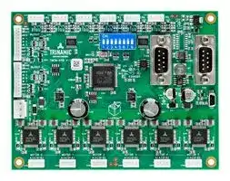
Illustrative purposes only

TMCM-6110
Stepper Motor Driver, 2-Phase, 6-Axis, 1.1A, 24V DC Output, USB, RS485, CAN
⚠️ Reference pricing provided. In case of supply shortages, we will connect you with our trusted procurement partners to ensure your project's continuity.
- Manufacturer: TRINAMIC / ANALOG DEVICES
- Product type: Stepper Motor Drives
- Supply Voltage Min:9V; Supply Voltage Max:28V; No. of Phases:Two Phase; Power Rating:-; Output Voltage Max:24V; Output Current:1.1A; Product Range:-; SVHC:No SVHC (27-Jun-2018)
- SVHC: No SVHC (04-Feb-2026)
- No. of Phases: Two Phase
- Product Range: TMCM StepRocker
- Output Current Max: 1.1A
- Supply Voltage Max: 28VDC
- Supply Voltage Min: 9VDC
- Control / Drive Type: 6-Axis Controller / Driver Module
| Delivery and price | |
|---|---|
| Units per pack | 1 |
| Price | 238.01 € |
| Current stock | 100+ |
| Lead time | 30 days |
Datasheet

**MODULE FOR** **`STEPPER MOTORS MODULE`**

## **Hardware Version V1.10**

## **HARDWARE MANUAL**

**==> picture [256 x 5] intentionally omitted <==**

**----- Start of picture text -----**<br>
+  +<br>**----- End of picture text -----**<br>


**==> picture [268 x 166] intentionally omitted <==**

**----- Start of picture text -----**<br>
SeSo ee picid 2 eves<br>avgete(ROUT. 2... 0104 eesST bios (Patit Tl6 IE eeeeee e a<br>[sas hee | Wore" | SS o~<br>utSUTpalaeasSCpanieeTien.Og ingour_2—~awaePSsen2a TRINAMICTweu-60EEE VAL.rae%Sy ERCSERggvares Ea STKigAL | feyiaaasitnibttehsoot a,ca ceaoe‘aliimeALciw|  | |Il easae,S|iere.oe I=,sy  || 1| 0<br>we ae | es Ey i Vey”<br>bie meme See 2 econ) ) Ban Ge<br>icabe ge ‘es 88 = amend chant! —<br>ee BUTrsmae2 ooEg oe MM= finelyLIE3 Fe2 Beigezt2SHela ‘tesi intenA ‘tn 3tal e601 aea@ ese34 coeBacto&thy |)iF<br>Be ravenfi oe= =NaH aA=A Wid \BG  Ahg wm.gt aN=<br>(iS “3eee 4a ee= Beet ae eeS001 taree Been)a me espoe eeae[BeenOcal<br>© RNIN mint ARTUR Se HHRRTTE27) gee RUEET<br>&.3 pon ax yw> ea z| R,¥Ae)Se REityoeSea uitwae Seeg m=Se aug<br>MuTOR O MOTOR 1 WOfOR 2 MOTOR 3 WOTOK # 4Or0R. 5. .<br>— AiA2 91 82 A1A281 82. AiA28182 ALA2 B18: AL LB A1A291<br>+  0d a ih: i i 8: Oe +<br>**----- End of picture text -----**<br>


## **TMCM-6110**

**`6 Axes Stepper Controller / Driver 1.1A RMS / 24V DC USB, CAN, RS485 [or RS232]`**

TRINAMIC Motion Control GmbH & Co. KG Hamburg, Germany

## **www.trinamic.com**

TMCM-6110 Hardware Manual (Rev. 1.14 / 2014-DEC-10)

2

## **Table of Contents**

|1|Features ........................................................................................................................................................................... 3|
|---|---|
|2|Order Codes ................................................................................................................................................................... 4|
|3|Mechanical and Electrical Interfacing ..................................................................................................................... 5|
||3.1<br>Size of Board ......................................................................................................................................................... 5|
||3.2<br>Board mounting considerations ...................................................................................................................... 5|
||3.2.1<br>DIN Rail Mounting ......................................................................................................................................... 6|
||3.3<br>Connectors ............................................................................................................................................................. 6|
||3.3.1<br>Power Connector ........................................................................................................................................... 8|
||3.3.2<br>I/O Connector 0 .............................................................................................................................................. 8|
||3.3.3<br>I/O Connector 1 .............................................................................................................................................. 9|
||3.3.4<br>Motor Connector 0-5 ..................................................................................................................................... 9|
||3.3.5<br>Reference Switch Connector 0-5 ............................................................................................................... 9|
||3.3.6<br>CAN Connector ............................................................................................................................................. 10|
||3.3.7<br>RS485 Connector .......................................................................................................................................... 10|
||3.3.8<br>USB Connector .............................................................................................................................................. 10|
||3.4<br>Power Supply ...................................................................................................................................................... 11|
||3.5<br>Communication .................................................................................................................................................. 11|
||3.5.1<br>RS485 ............................................................................................................................................................... 11|
||3.5.2<br>CAN .................................................................................................................................................................. 13|
||3.5.3<br>USB................................................................................................................................................................... 13|
||3.6<br>Inputs and Outputs ........................................................................................................................................... 15|
||3.6.1<br>Reference Switch Inputs ........................................................................................................................... 15|
||3.6.2<br>General Purpose Inputs ............................................................................................................................. 15|
||3.6.3<br>General Purpose Outputs .......................................................................................................................... 16|
|4|Motor driver current .................................................................................................................................................. 17|
|5|On-board LEDs ............................................................................................................................................................. 19|
|6|Reset to Factory Defaults ......................................................................................................................................... 20|
|7|Functional Description .............................................................................................................................................. 21|
|8|Using the RS232 assembly option instead of RS485....................................................................................... 22|
|9|Position of connectors .............................................................................................................................................. 23|
|10 Operational Ratings ................................................................................................................................................... 24||
|11 Life Support Policy ..................................................................................................................................................... 26||
|12 Revision History .......................................................................................................................................................... 27||
||12.1<br>Document Revision ........................................................................................................................................... 27|
||12.2<br>Hardware Revision ............................................................................................................................................ 27|
|13 References..................................................................................................................................................................... 27||


www.trinamic.com

TMCM-6110 Hardware Manual (Rev. 1.14 / 2014-DEC-10)

## **1 Features**

The TMCM-6110 is a compact 6-axes stepper motor controller/driver standalone board. It supports up to 6 bipolar stepper motors with up to 1.1A RMS coil current. There are separate motor and reference/end switch connectors for each motor. In addition, the module offers 8 general purpose inputs and 8 general purpose outputs.

## **MAIN CHARACTERISTICS**

## **Motion controller**

- Motion profile calculation in real-time

-

   - On the fly alteration of motor parameters (e.g. position, velocity, acceleration)

- High performance microcontroller for overall system control and serial communication protocol handling

## **Bipolar stepper motor driver**

- Up to 256 microsteps per full step

- High-efficient operation, low power dissipation

- Dynamic current control

- Integrated protection

- stallGuard2™ feature for stall detection

- coolStep™ feature for reduced power consumption and heat dissipation

## **Interfaces**

- Up to 8 multi-purpose inputs (+24V compatible, incl. 2 dedicated analog inputs)

-

   - Up to 8 multi-purpose outputs (open-drain, incl. 2 outputs for currents up to 1A)

- RS485 2-wire communication interface

- USB 2.0 full speed (12Mbit/s) communication interface (mini-USB connector)

- CAN 2.0B communication interface (9pin D-SUB)

## **Features**

-

Uses TMC429 stepper motor controller for on-the-fly alteration of many motion specific parameters

- Uses TMC260 advanced stepper motor driver IC

- Up to 256 microsteps per fullstep

- Integrated protection: overtemperature/undervoltage

## **Software**

- TMCL remote (direct mode) and standalone operation (memory for up to 2048 TMCL commands)

- Fully supported by TMCL-IDE (PC based integrated development environment)

## **Electrical data**

- Supply voltage: +9V… +28V DC - Motor current: up to 1.1A RMS (programmable) per axis

## **Mechanical data**

-

Board size: 130mm x 100mm, height 30mm max.

- 4 mounting holes for M3 screws

Please see separate TMCL Firmware Manual for additional information

www.trinamic.com

TMCM-6110 Hardware Manual (Rev. 1.14 / 2014-DEC-10)

4

## **2 Order Codes**

|**Order code**|**Description**|**Size of unit**|
|---|---|---|
|TMCM-6110-_option_|6-axes bipolar stepper motor controller and driver<br>module|<br>130mm x 100mm x 30mm|
||||


## **Table 2.1 TMCM-6110 order codes**

The following options are available:

|**Firmware option**|**Description**|**Order code example:**|
|---|---|---|
|-TMCL|Modulepre-programmed with TMCL firmware|TMCM-6110-_TMCL_|


## **Table 2.2 TMCM-6110 firmware options**

A version with RS232 interface and 9pin female D-SUB connector instead of RS485 is available as assembly option upon request (please see chapter x.xx for adding RS232 interface option instead of RS485 to standard version for prototyping):

|**Interface option**|**Description**|**Order code example:**|
|---|---|---|
|-232|Module with RS232 interface instead of RS485|TMCM-6110-_232_-TMCL|


## **Table 2.3 TMCM-6110 interface options**

A cable loom set is available for this module.

|**Order code**|**Description**|
|---|---|
|TMCM-6110-CABLE|The cable loom for TMCM-6110 contains:<br>-<br>1x Cable loom for power connector<br>-<br>6x cable loom for reference switch connectors 0-5<br>-<br>6x cable loom for motor connector 0-5<br>-<br>2x cable loom for I/O connector 0+1<br>-<br>1x USB type A connector to mini-USB type B connector cable|
|||


**Table 2.4 Cable loom order code**

www.trinamic.com

TMCM-6110 Hardware Manual (Rev. 1.14 / 2014-DEC-10)

5

## **3 Mechanical and Electrical Interfacing**

## **3.1 Size of Board**

The board with the controller / driver electronics has an overall size of 130mm x 100mm and offers four mounting holes for M3 screws (3.2mm diameter). Maximum board height (without mating connectors and cable looms) is about 30mm (approx. 26mm above printed circuit board level).

**==> picture [376 x 288] intentionally omitted <==**

**----- Start of picture text -----**<br>
130<br>125<br>5<br>5<br>4x M3 screws<br>for mounting<br>100 95<br>5<br>**----- End of picture text -----**<br>


**Figure 3.1 Board dimensions and position of mounting holes (all values in mm).**

## **3.2 Board mounting considerations**

The TMCM-6110 offers four metal plated mounting holes. All four mounting holes are connected to system and signal ground (same as power supply ground).

In order to minimize distortion of signals and radiation of HF signals (improve EMC compatibility) especially in sensitive / noisy environments it is important to ensure a solid ground connection within the system. In order to support this, it is recommended to connect all four mounting holes of the board in addition to the supply ground connection to system power supply ground.

Nevertheless, this might not always be an option e.g. in case the metal system chassis / TMCM-6110 mounting plate is already connected to earth and a direct connection between supply ground (secondary side) and mains supply earth (primary side) is not desired / not an option. In this case plastic (e.g. made of nylon) spacers / distance bolts should be used.

www.trinamic.com

TMCM-6110 Hardware Manual (Rev. 1.14 / 2014-DEC-10)

6

## **3.2.1 DIN Rail Mounting**

The board has been designed in order to support DIN rail mounting. One dimension of the board has been limited to 100mm and there is a minimum border of approx. two millimeters alongside all four corners of the board free of any component. This way, a standard mounting carrier for DIN rails as it is available from several sources might be used as adapter for DIN rail mounting of the board.

## **EXAMPLE**

Mounting carrier for DIN 35 rail from WAGO® (288-003) cut to the length of the TMCM-6110 board (130mm) with populated TMCM-6110.

**Figure 3.2 DIN rail mounting**

## **3.3 Connectors**

The TMCM-6110 has 18 connectors altogether. There are 6 separate connectors for each motor and corresponding reference switches (Figure 4.4), two I/O connectors, one power connector and 3 connectors for communication incl. Mini-USB, RS485 and CAN.

**==> picture [433 x 267] intentionally omitted <==**

**----- Start of picture text -----**<br>
Reference switch connectors<br>Axis 0 Axis 1 Axis 2 Axis 3 Axis 4 Axis5 CAN connector<br>00,00, 1 4 1 4 00 1 4 00 1 4 00 1 4 00 1 4<br>7 = yx) re en me zs a_i =<br>, SY TET ‘eee as, ae a Bis iy = Te 1<br>1 oweBreeI Duieicaite RETrgaosunmgntecesuunegeCOEmehAreeRESSE TNPeeaue:SOs braAKa TeneeooTY Ge SAASjisBa PapeCybe, suesEMO oe €:4 RS485 connector<br>I/O connector 0 UTseHeese Og naeDoreen!oea Pe |iriissnpages.ee“iof wien\ heen|tit 5 ~©.@ ‘|=| ees,aos[=o ame 5 afSig<br>C)© 101 BNVCS,seoeevanes" iour2—PSsoo TRINAMETucu-enoHEEil vil. SeaSAAIvestcSoe@ EE ieei Sra"=|res| takccoFoe4 on 0oeCand VONcySd‘| Ol: 1 Be aeaa-_ayan* Olinai 69 eee.- pass2i || 1 ae 69<br>I/O connector 1 Taio,Cees es mereaE p=te =e2 so4 ||GetDee ma@<br>purse<br>2 es , mit 3= = Seay =: [a8 oY<br>O 10 eeiS aS Mwyns 8a5 —— ANASee Ciotendyx, A // remy “usexz0z<br>Power connector O 1 2m= |POWER = fn\ \ 3Saee Wfh nO\ wh aob = Mini-USB connector<br>3 i—° ‘waveS22a‘ee 8 _ 1aETa Penswt 2.feor eeeAG BeStee Ecoeas,eei e 18 a.vateeoFDD mei Beets‘otv1ree,Bl<br>— = on itil} oe pee TT Di ts SeeneraH © pa TUNER REEE P20) CEEREREERES<br>Pleesyaawasn = 1 tot=> ‘ aef ‘ei au= oawk Se4g [eo] a= [=] 2Bre pos:= .asi §<br>oe ie lS et Ug, gusstsn sin Un SOHNE 7 a ssisegpsae i=) te Sssisant j= !<br>= woToR 0 :  UoToR1r bay 0 iMOTOR 3 "ii Satis) 6pel Ev,<br>e<br>AiA28182: A1A7 8182 AIA2 8182 AIA28182 an: = ®<br>1 4 1 4 1 4 1 4 1 4 1 4<br>Axis 0 Axis 1 Axis 2 Axis 3 Axis 4 Axis5<br>Motor connectors<br>**----- End of picture text -----**<br>


**Figure 3.3 TMCM-6110 connectors**

www.trinamic.com

TMCM-6110 Hardware Manual (Rev. 1.14 / 2014-DEC-10)

7

## **OVERVIEW OF CONNECTOR AND MATING CONNECTOR TYPES**

|**Label**|**Connector type**|**Mating connector type**|
|---|---|---|
||JST B3P-VH<br>(JST VH series, 3pins, 3.96mm<br>pitch)|Connector housing: JST VHR-3N<br>Contacts: JST SVH-21T-P1.1<br>Wire: 0.83mm2,AWG 18|
|Power Connector|||
||||
||CI0104P1VK0-LF<br>CVIlux CI01 series, 4 pins, 2mm<br>pitch|Connector housing CVIlux: CI01045000-A<br>Contacts CVIlux: CI01T011PE0-A<br>_or_<br>Connector housing JST: PHR-4<br>Contacts JST: SPH-002T-P0.5S<br>Wire: 0.22mm2|
|Motor Connectors|||
||||
||CI0104P1VK0-LF<br>CVIlux CI01 series, 4 pins, 2mm<br>pitch|Connector housing CVIlux: CI01045000-A<br>Contacts CVIlux: CI01T011PE0-A<br>_or_<br>Connector housing JST: PHR-4<br>Contacts JST: SPH-002T-P0.5S<br>Wire: 0.22mm2|
|Reference Switch<br>Connectors|||
||||
||CI01010P1VK0-LF<br>CVIlux CI01 series, 10 pins,<br>2mm pitch|Connector housing CVIlux: CI010105000-A<br>Contacts CVIlux: CI01T011PE0-A<br>_or_<br>Connector housing JST: PHR-10<br>Contacts JST: SPH-002T-P0.5S<br>Wire: 0.22mm2|
|I/O Connector 0 + 1|||
||||
||Molex 500075-1517<br>Mini USB Type B vertical<br>receptacle|Any standard mini-USB plug|
|Mini-USB Connector|||
||||
||Tyco electronics 3-1634218-2<br>D-SUB socket with 4-40 female<br>screwlocks|Any standard D-SUB female 9-pin|
|RS485 Connector|||
||||
|CAN Connector|Male D-SUB 9-pin|Anystandard D-SUB female 9-pin|


**Table 3.1 Connectors and mating connectors, contacts and applicable wire**

www.trinamic.com

TMCM-6110 Hardware Manual (Rev. 1.14 / 2014-DEC-10)

8

## **3.3.1 Power Connector**

The module offers a single power connector with the option to have separate supply for driver electronics and digital controller part. A single supply voltage is sufficient, all further voltages required e.g. for the digital components are generated on-board.

|1<br>3|**Pin**<br>~~a~~|**Label**<br>~~a~~|**Direction**<br>~~a~~|**Description**<br>~~a~~<br>~~|~~|
|---|---|---|---|---|
||1<br>~~a~~<br>~~a~~|GND<br>~~a~~<br>~~a~~|Power(GND)<br>~~a~~<br>~~a~~|Common system supplyand signalground<br>~~a~~<br>~~|~~<br>~~a~~|
||2|VDRIVER|Power<br>(Supply input)|Stepper driver supply voltage. Without this voltage stepper<br>driver ICs and therefore any motor connected will not be<br>energized|
||3|VDIGITAL|Power<br>(Supply input)|Supply voltage for everything else apart from the stepper<br>motor driver ICs. On-board voltage regulator will generate<br>the necessary voltages for the digital circuits from this<br>supply. This pin can be left unconnected. In this case a<br>diode between VDRIVERand VDIGITALwill ensure supply of the<br>digital parts.<br>_Please note:_<br>-<br>_The diode has a current rating of 3A. As VDIGTIAL is_<br>_available at the I/O connectors and the reference_<br>_switch connectors also, always connect this pin to_<br>_positive supply voltage in case substantial amount of_<br>_current is withdrawn from these pins for external_<br>_circuits._<br>-<br>_It is expected that VDIGITAL and VDRIVER are connected to_<br>_the same power supply output when both pins are_<br>_used. Otherwise please ensure that VDIGITAL is always_<br>_equal or higher than VDRIVER when connected (due to_<br>_the diode). _|


**Table 3.2 Power connector**

## **3.3.2 I/O Connector 0**

The module offers two I/O connectors. The number and type of inputs, outputs and supply is the same for both connectors. Therefore, if only half of the inputs / outputs etc. is required it will be sufficient to use just one of the two connectors and reduce / simplify cabling.

|1<br>10<br>og~~EP~~<br>~~a~~<br>~~a~~|**Pin**<br>~~a~~|**Label**<br>~~a~~|**Direction**<br>~~a~~<br>~~a~~|**Description**<br>~~a~~<br>~~ee~~|
|---|---|---|---|---|
||1<br>~~a~~<br>~~a~~|GND<br>~~a~~<br>~~a~~|Power (GND)<br>~~a~~<br>~~a ~~<br>~~a~~|GND<br>~~a~~<br> ~~ee~~<br>~~a~~|
||2<br>~~a~~<br>~~a~~|VDIGITAL<br>~~a~~<br>~~a~~|Power<br>(Supplyoutput)<br>~~a~~<br>~~a~~|Connected to VDIGITALof Power connector<br>~~a~~<br>~~a~~|
||3<br>~~i~~|AIN_0<br>~~i~~|Input<br>~~i~~|Dedicated analog input,<br>input voltage range: 0… +10V,<br>resolution: 12bit (0… 4095)<br>~~i~~|
||4<br>~~EP~~|IN_1<br>~~EP~~|Input<br>~~EP~~|Digital input (+24V compatible)<br>Home switch input for motor 0<br>~~EP~~|
||5<br>~~EP~~<br>~~a~~|IN_2<br>~~EP~~<br>~~a~~|Input<br>~~EP~~<br>~~a~~<br>~~a~~|Digital input (+24V compatible)<br>Home switch input for motor 1<br>~~EP~~<br>~~a~~<br>~~a~~|
||6<br>~~a~~|IN_3<br>~~a~~|Input<br>~~a~~|Digital input (+24V compatible)<br>Home switch input for motor 2<br>~~a~~|
||7<br>~~a~~<br>~~a~~|OUT_0<br>~~a~~<br>~~a~~|Output<br>~~a~~<br>~~a~~|Open-drain output (max. 100mA)<br>Integrated freewheelingdiode<br>~~a~~<br>~~a~~|
||8<br>~~a~~|OUT_1<br>~~a~~|Output<br>~~a~~|Open-drain output (max. 100mA)<br>Integrated freewheelingdiode<br>~~a~~|
||9<br>~~a~~|OUT_2<br>~~a~~|Output<br>~~a~~|Open-drain output (max. 100mA)<br>Integrated freewheelingdiode<br>~~a~~|
||10<br>~~a~~|OUT_3<br>~~a~~|Output<br>~~a~~|Open-drain output (max. 1A)<br>Integrated freewheelingdiode<br>~~a~~|


**Table 3.3 I/O connector 0**

www.trinamic.com

TMCM-6110 Hardware Manual (Rev. 1.14 / 2014-DEC-10)

9

## **3.3.3 I/O Connector 1**

The module offers two I/O connectors. The number and type of inputs, outputs and supply is the same for both connectors. Therefore, if only half of the inputs / outputs etc. is required it will be sufficient to use just one of the two connectors and reduce / simplify cabling.

|1<br>10<br>og <br>~~a~~|**Pin**<br>~~On~~|**Label**<br>~~On~~|**Direction**<br>~~On~~|**Description**<br>~~e'_"_~~|
|---|---|---|---|---|
||1<br>~~On~~<br>~~e~~|GND<br>~~On~~<br>~~e~~|Power (GND)<br>~~On~~<br>~~e~~|GND<br>~~e'_"_~~<br>~~es~~|
||2<br>~~e~~|VDIGITAL<br>~~e~~|Power<br>(Supply output)<br>~~e~~|Connected to VDIGITALof Power connector<br>~~es~~|
||3<br>~~e~~|AIN_4<br>~~e~~|Input<br>~~e~~|Dedicated analog input,<br>input voltage range: 0… +10V,<br>resolution: 12bit(0… 4095)<br>~~es~~|
||4<br> ~~ED~~|IN_5<br>~~ED~~|Input<br>~~ED~~|Digital input (+24V compatible)<br>Home switch input for motor 3<br>~~ED~~|
||5<br>~~a~~|IN_6<br>~~a~~|Input<br>~~a~~|Digital input (+24V compatible)<br>Home switch input for motor 4<br>~~a~~|
||6<br>~~a~~<br>~~a~~|IN_7<br>~~a~~<br>~~a~~|Input<br>~~a~~<br>~~a~~|Digital input (+24V compatible)<br>Home switch input for motor 5<br>~~a~~<br>~~a~~|
||7<br>~~a~~|OUT_4<br>~~a~~|Output<br>~~a~~|Open-drain output (max. 100mA)<br>Integrated freewheelingdiode<br>~~a~~|
||8<br>~~a~~<br>~~a~~|OUT_5<br>~~a~~<br>~~a~~|Output<br>~~a~~<br>~~a~~|Open-drain output (max. 100mA)<br>Integrated freewheelingdiode<br>~~a~~<br>~~a~~|
||9<br>~~a~~|OUT_6<br>~~a~~|Output<br>~~a~~|Open-drain output (max. 100mA)<br>Integrated freewheelingdiode<br>~~a~~|
||10<br>~~a~~<br>~~a~~|OUT_7<br>~~a~~<br>~~a~~|Output<br>~~a~~<br>~~a~~|Open-drain output (max. 1A)<br>Integrated freewheelingdiode<br>~~a~~<br>~~a~~|


**Table 3.4 I/O connector 1**

## **3.3.4 Motor Connector 0-5**

For each stepper motor axis a separate 4 pin connector is available.

|1<br>4<br>~~Sl~~|**Pin**<br>~~Sl~~|**Label**<br>~~Sl~~|**Direction**<br>~~Sl~~|**Description**<br>~~Sl~~|
|---|---|---|---|---|
||1<br>~~Sl~~|A1<br>~~Sl~~|Output<br>~~Sl~~|Pin 1 of motor coil A<br>~~Sl~~|
||2<br>~~Sl~~<br>~~a~~|A2<br>~~Sl~~<br>~~a~~|Output<br>~~Sl~~<br>~~————~~|Pin 2 of motor coil A<br>~~Sl~~<br>~~————~~|
||3<br>~~a~~|B1<br>~~a~~|Output<br>~~————~~|Pin 1 of motor coil B<br>~~————~~|
||4<br>~~a~~|B2<br>~~a~~|Output<br>~~————~~|Pin 2 of motor coil B<br>~~————~~|


**Table 3.5 Motor connector**

## **3.3.5 Reference Switch Connector 0-5**

For each stepper motor axis a separate reference / limit switch input connector is available.

**==> picture [459 x 68] intentionally omitted <==**

**Table 3.6 Reference switch connector**

www.trinamic.com

TMCM-6110 Hardware Manual (Rev. 1.14 / 2014-DEC-10)

10

## **3.3.6 CAN Connector**

A CAN 2.0B interface is available via a standard 9-pin male D-SUB connector. Only three pins of this connector are used. Pin assignment of these three pins is according to CiA Draft Recommendation Part 1: cabling and connector pin assignment.

## ~~PT~~ CAN interface will be de-activated in case USB is connected due to internal sharing of hardware resources.

**==> picture [459 x 348] intentionally omitted <==**

**----- Start of picture text -----**<br>
PC“a Pin  1  Label  Direction  Description  eC<br>| 2  CAN_L  Bi-directional  Differential CAN bus signal (inverting)<br>O 5 9 a 3  GND  Power (GND) Signal and system ground<br>a 4<br>|<br>1 6 5<br>O SO<br>6<br>7  CAN_H  Bi-directional  Differential CAN bus signal (non-inverting)<br>SO 8<br>a 9<br>RS485 Connector<br>An RS485 interface is available via a 9-pin male D-SUB connector.<br>a Pin  Label  a Direction  ee Description<br>a 1<br>2  RS485-  Bi-directional  Differential RS485 bus signal (inverting)<br>3  GND  Power (GND)  Signal and system ground<br>O 5 9 a 4<br>5<br>1 | 6 6<br>Ok a<br>Bi-directional  Differential RS485 bus signal (non-<br>7  RS485+<br>inverting)<br>a 8<br>a 9<br>**----- End of picture text -----**<br>


**Table 3.7 CAN connector**

## **3.3.7 RS485 Connector**

An RS485 interface is available via a 9-pin male D-SUB connector.

**Table 3.8 RS485 connector**

## **3.3.8 USB Connector**

A USB interface is available via a Mini-USB connector. This module supports USB 2.0 Full-Speed (12Mbit/s) connections.

CAN interface will be deactivated as soon as USB is connected (VBUS voltage available)

On-board digital core logic (mainly processor and EEPROM) will be powered via USB in case no other supply is connected. This can be used to set parameters / download TMCL programs or perform firmware updates with the module connected via USB only or inside the machine while the machine is powered off.

**==> picture [445 x 79] intentionally omitted <==**

**----- Start of picture text -----**<br>
a Pin  Label  a Direction  Description<br>a 1  VBUS  Power (+5V input)  +5V supply from Host<br>5 SC 2  D-  Bi-directional  USB Data -<br>1 a 3  D+  Bi-directional  USB Data +<br>sO 4  ID  Connected to signal and system ground<br>a 5  GND  Power (GND) Signal and System ground<br>**----- End of picture text -----**<br>


**Table 3.9 USB connector**

www.trinamic.com

TMCM-6110 Hardware Manual (Rev. 1.14 / 2014-DEC-10)

11

## **3.4 Power Supply**

For proper operation care has to be taken with regard to power supply concept and design. The board offers 2000uF / 35V electrolytic buffer capacitors and additionally about 120uF / 35V ceramic capacitors for supply voltage filtering.

**==> picture [500 x 160] intentionally omitted <==**

**----- Start of picture text -----**<br>
VDRIVER 6x TMC260<br>(stepper driver ICs)<br>SMBJ28A<br>Power<br>1000µF 1000µF<br>connector SK36<br>GND GND GND Supply of other circuits<br>VDIGITAL via on-board regulators<br>: [t]<br>VDIGITAL on I/O connector 0 + 1<br>SMBJ28A VDIGITAL on Reference switch connector 0-5<br>100µF<br>T<br>GND GND<br>**----- End of picture text -----**<br>


## **Figure 3.4 TMCM-6110 power supply concept**

## **HINTS FOR POWER SUPPLY**

- keep power supply cables as short as possible

- use large diameters for power supply cables

**CAUTION!**

_**Do not connect or disconnect motor during operation!**_ Motor cable and motor inductivity might lead to voltage spikes when the motor is disconnected / connected while energized. These voltage spikes might exceed voltage limits of the driver MOSFETs and might permanently damage them. Therefore, always disconnect power supply before connecting / disconnecting the motor. _**Keep the power supply voltage**_ **(VDRIVER** _**and**_ **VDIGITAL)** _**below the upper limit of 28V!**_ ~~bd~~ Otherwise the driver electronics will seriously be damaged! Especially, when the selected operating voltage is near the upper limit a regulated power supply is highly ~~oO~~ recommended. Please refer to chapter 0 (operating values). _**There is no reverse polarity protection!**_ The module will short any reversed supply voltage due to internal diodes of the driver transistors. ~~eo~~

## **3.5 Communication**

## **3.5.1 RS485**

For remote control and communication with a host system the TMCM-6110 provides a two wire RS485 bus interface. For proper operation the following items should be taken into account when setting up an RS485 network:

1. _BUS STRUCTURE_ :

   - The network topology should follow a bus structure as closely as possible. That is, the connection between each node and the bus itself should be as short as possible. Basically, it should be short compared to the length of the bus.

www.trinamic.com

TMCM-6110 Hardware Manual (Rev. 1.14 / 2014-DEC-10)

12

**==> picture [371 x 115] intentionally omitted <==**

**----- Start of picture text -----**<br>
Host<br>Slave Slave Slave<br>c:> node node node<br>1 n  - 1 n<br>}<br>termination termination<br>resistor resistor<br>(120 Ohm) (120 Ohm)<br>RS485 keep distance as<br>short as possible<br>**----- End of picture text -----**<br>


**Figure 3.3: Bus structure**

2. _BUS TERMINATION_ :

   - Especially for longer busses and/or multiple nodes connected to the bus and/or high communication speeds, the bus should be properly terminated at both ends. The TMCM-6110 does not integrate any termination resistor. Therefore, 120 Ohm termination resistors at both ends of the bus have to be added externally.

3. _NUMBER OF NODES_ : The RS485 electrical interface standard (EIA-485) allows up to 32 nodes to be connected to a single bus. The bus transceiver used on the TMCM-6110 (SN65HVD3082ED) has a significantly reduced bus load and allows a maximum of 255 units to be connected to a single RS485 bus using TMCL firmware. _Please note: usually it cannot be expected to get reliable communication with the maximum number of nodes connected to one bus and maximum supported communication speed at the same time. Instead, a compromise has to be found between bus cable length, communication speed and number of nodes._

## _4. COMMUNICATION SPEED:_

The maximum RS485 communication speed supported by the TMCM-6110 is 115200 bit/s. Factory default is 9600 bit/s. _Please see separate TMCM-6110 TMCL firmware manual for information regarding other possible communication speeds._

5. _NO FLOATING BUS LINES:_

Avoid floating bus lines while neither the host/master nor one of the slaves along the bus line is transmitting data (all bus nodes switched to receive mode). Floating bus lines may lead to communication errors. In order to ensure valid signals on the bus it is recommended to use a resistor network connecting both bus lines to well defined logic levels.

There are actually two options which can be recommended: Add resistor (Bias) network on **one** side of the bus, only (120R termination resistor still at **both** ends):

**==> picture [379 x 137] intentionally omitted <==**

**----- Start of picture text -----**<br>
Slave Slave<br>node node +5V<br>n  - 1 n<br>pull-up (680R)<br>termination RS485+ / RS485A termination<br>resistor resistor<br>(220R) RS485- / RS485B (120R)<br>pull-down (680R)<br>GND<br>**----- End of picture text -----**<br>


**Figure 3.4: Bus lines with resistor (Bias) network on one side, only**

Or add resistor (Bias) network at **both** ends of the bus (like Profibus™ termination):

www.trinamic.com

TMCM-6110 Hardware Manual (Rev. 1.14 / 2014-DEC-10)

13

**==> picture [404 x 138] intentionally omitted <==**

**----- Start of picture text -----**<br>
Slave Slave<br>+5V node node +5V<br>n  - 1 n<br>pull-up (390R) pull-up (390R)<br>termination RS485+ / RS485A termination<br>resistor resistor<br>(220R) RS485- / RS485B (220R)<br>pull-down (390R) pull-down (390R)<br>GND GND<br>**----- End of picture text -----**<br>


**Figure 3.5: Bus lines with resistor (Bias) network at both ends**

## **3.5.2 CAN**

For remote control and communication with a host system the TMCM-6110 provides a CAN bus interface. Please note that the CAN interface is not available in case USB is connected. For proper operation the following items should be taken into account when setting up a CAN network:

## 1. _BUS STRUCTURE_

The network topology should follow a bus structure as closely as possible. That is, the connection between each node and the bus itself should be as short as possible. Basically, it should be short compared to the length of the bus.

**==> picture [370 x 114] intentionally omitted <==**

**----- Start of picture text -----**<br>
Host<br>Slave Slave Slave<br>c:> node node node<br>1 n  - 1 n<br>}<br>termination termination<br>resistor resistor<br>(120 Ohm) (120 Ohm)<br>CAN keep distance as<br>short as possible<br>**----- End of picture text -----**<br>


## **Figure 3.7 CAN bus structure**

## 2. _BUS TERMINATION_

- Especially for longer busses and/or multiple nodes connected to the bus and/or high communication speeds, the bus should be properly terminated at both ends. The TMCM-6110 does not integrate any termination resistor. Therefore, 120 Ohm termination resistors at both ends of the bus have to be added externally.

## 3. _NUMBER OF NODES_

The bus transceiver used on the TMCM-6110 units (TJA1050T) supports at least 110 nodes under optimum conditions. Practically achievable number of nodes per CAN bus highly depends on bus length (longer bus -> less nodes) and communication speed (higher speed -> less nodes).

## **3.5.3 USB**

For remote control and communication with a host system the TMCM-6110 provides a USB 2.0 full-speed (12Mbit/s) interface (mini-USB connector). As soon as a USB-Host is connected the module will accept commands via USB. The CAN interface will be de-activated then.

The TMCM-6110 support USB self powered operation (when an external power is supplied via the power supply connector) and USB bus powered operation, also (no external power supply via power supply connector). During USB bus powered operation, only the core digital circuit parts will be operational. That is, the microcontroller itself and also the EEPROM. Motor movements will not be possible. This mode has been implemented in order to enable configuration / parameter setting / read-out, firmware updates etc. by just

www.trinamic.com

TMCM-6110 Hardware Manual (Rev. 1.14 / 2014-DEC-10)

14

connecting a USB cable between the module and a host PC. No additional cabling / external devices as e.g. power supply etc. are required in that case.

Please note that the module might draw current from the USB +5V bus supply even in USB self powered operation depending on the voltage level of this supply.

www.trinamic.com

TMCM-6110 Hardware Manual (Rev. 1.14 / 2014-DEC-10)

15

## **3.6 Inputs and Outputs**

## **3.6.1 Reference Switch Inputs**

The six reference switch connectors – one for each stepper motor axis – offer two reference switch inputs each, REF_L and REF_R.

Both inputs offer the same input circuit with voltage resistor dividers, limiting diodes against over- and under-voltage and programmable 1k pull-ups to +5V. The programmable pull-ups can be switched on or off separately for the first three axes / first three reference switch connectors 0-2 and the second three axes / reference switch connectors 3-5.

**==> picture [243 x 178] intentionally omitted <==**

**----- Start of picture text -----**<br>
+5V<br>1k<br>REF_L, +3.3V<br>REF_R<br>10k<br>TMC429<br>22k<br>1nF<br>GND GND GND<br>**----- End of picture text -----**<br>


**Figure 3.8 Reference switch input circuit (simplified diagram)**

With TMCL firmware commands `GAP 10, 0` and `GAP 11, 0` can be used to read out the status of the reference switch inputs. See _TMCL Firmware Manual_ chapter 5 about _Axis parameters_ and _Reference search_ for more details.

## **3.6.2 General Purpose Inputs**

The TMCM-6110 offers two I/O connectors with 8 inputs altogether including two dedicated analog inputs. All inputs offer the same basic input protection circuit. The dedicated analog inputs have different input voltage dividers in order to support a full scale input voltage range of 0…+10V. The other digital inputs have been designed in order to be able to accept +5V and +24V signal levels.

**==> picture [278 x 142] intentionally omitted <==**

**----- Start of picture text -----**<br>
IN_1,<br>IN_2,<br>IN_3, +3.3V<br>IN_5,<br>IN_6,<br>IN_7 10k<br>microcontroller<br>22k<br>1nF<br>GND GND GND<br>**----- End of picture text -----**<br>


## **Figure 3.9 General purpose digital input circuit**

With TMCL firmware command `GIO <` _`n>, 0`_ can be used to read out the status of the digital input _<n>_ . See _TMCL Firmware Manual_ command GIO for more details.

www.trinamic.com

TMCM-6110 Hardware Manual (Rev. 1.14 / 2014-DEC-10)

16

**==> picture [275 x 120] intentionally omitted <==**

**----- Start of picture text -----**<br>
AIN_0, +3.3V<br>AIN_4<br>22k<br>microcontroller<br>10k<br>1nF<br>GND GND GND<br>**----- End of picture text -----**<br>


## **Figure 3.10 General purpose analog input circuit**

With TMCL firmware command `GIO <` _`n>, 1`_ can be used to read out the analog / digital converted value of the analog input _<n>_ . See _TMCL Firmware Manual_ command GIO for more details.

The function of the inputs might differ depending on firmware version.

## **3.6.3 General Purpose Outputs**

The TMCM-6110 offers two I/O connectors with 8 outputs altogether. All outputs are open-drain outputs. For all outputs a freewheeling diode (to VDIGTAL) is already integrated.

Nevertheless, two output offer more powerful MOSFET driver transistors supporting currents up to 1A. All other have been designed for currents up to 100mA.

If VDIGITAL connection of the I/O connectors is used for supply of substantial current to any external circuit please make sure to connect VDIGTIAL in addition to VDRIVER of the power supply connector.

**==> picture [229 x 107] intentionally omitted <==**

**----- Start of picture text -----**<br>
VDIGITAL<br>OUT_0,<br>OUT_1,<br>OUT_2,<br>OUT_3,<br>OUT_4,<br>OUT_5, microcontroller<br>OUT_6,<br>OUT_7 GND<br>**----- End of picture text -----**<br>


**Figure 3.11 General purpose output (open-drain with freewheeling diode)**

With TMCL firmware command `SIO` _`<n>`_ `, 2, 1` can be used to set / pull-down the output _<n>_ . See _TMCL Firmware Manual_ command SIO for more details.

www.trinamic.com

TMCM-6110 Hardware Manual (Rev. 1.14 / 2014-DEC-10)

17

## **4 Motor driver current**

The on-board stepper motor driver operates current controlled. The driver current may be programmed in software for motor coil currents up-to 1.1A RMS with 32 effective scaling steps in hardware (CS in table below).

_Explanation of different columns in table below:_

_**Motor current**_ These are the values for TMCL axis parameter 6 (motor run current) and 7 (motor standby _**setting in**_ current). They are used to set the run / standby current using the following TMCL _**software (TMCL)**_ commands:

```
SAP 6, 0, <value> // set run current
SAP 7, 0, <value> // set standby current
```

(read-out value with `GAP` instead of `SAP` . Please see separate TMCM-6110 firmware manual for further information)

_**Motor current IRMS [A]**_

Resulting motor current based on motor current setting

|**Motor current**<br>**setting in**<br>**software(TMCL)**|**Current**<br>**scaling step**<br>**(CS)**|**Motor**<br>**current**<br>**ICOIL_PEAK[A]**|**Motor**<br>**current**<br>**ICOIL_RMS[A]**|
|---|---|---|---|
|0..7|0|<br>0.052|<br>0.036|
|8..15|1|0.103|0.073|
|16..23|2|0.155|0.109|
|24..31|3|0.206|0.146|
|32..39|4|0.258|0.182|
|40..47|5|0.309|0.219|
|48..55|6|0.361|0.255|
|56..63|7|0.413|0.292|
|64..71|8|0.464|0.328|
|72..79|9|0.516|0.365|
|80..87|10|0.567|0.401|
|88..95|11|0.619|0.438|
|96..103|12|0.670|0.474|
|104..111|13|0.722|0.510|
|112..119|14|0.773|0.547|
|120..127|15|0.825|0.583|
|128..135|16|0.877|0.620|
|136..143|17|0.928|0.656|
|144..151|18|0.980|0.693|
|152..159|19|1.031|0.729|
|160..167|20|1.083|0.766|
|168..175|21|1.134|0.802|
|176..183|22|1.186|0.839|
|184..191|23|1.238|0.875|
|192..199|24|1.289|0.912|
|200..207|25|1.341|0.948|
|208..215|26|1.392|0.984|
|216..223|27|1.444|1.021|
|224..231|28|1.495|1.057|
|232..239|29|1.547|1.094|
|240..247|30|1.598|1.130|
|248..255|31|1.650|1.167|


www.trinamic.com

TMCM-6110 Hardware Manual (Rev. 1.14 / 2014-DEC-10)

18

In addition to the settings in the table the motor current may be switched off completely (free-wheeling) using axis parameter 204 (see TMCM-6110 firmware manual).

www.trinamic.com

TMCM-6110 Hardware Manual (Rev. 1.14 / 2014-DEC-10)

19

## **5 On-board LEDs**

The board offers two LEDs in order to indicate board status. The function of both LEDs is dependent on firmware version.

With standard TMCL firmware the green LED should be slowly flashing during operation and the red LED should be off. Please see separate TMCM-6110 TMCL firmware manual for additional information.

When there is no valid firmware programmed into the board or during firmware update the red and green LEDs are permanently on.

**==> picture [46 x 36] intentionally omitted <==**

**----- Start of picture text -----**<br>
Red LED<br>Green LED<br>**----- End of picture text -----**<br>


**Figure 5.1 On-board LEDs**

www.trinamic.com

TMCM-6110 Hardware Manual (Rev. 1.14 / 2014-DEC-10)

20

## **6 Reset to Factory Defaults**

Since TMCL firmware version V1.13 it is possible to reset the TMCM-6110 module to factory default settings without establishing a communication link. This might be helpful in case communication parameters of the preferred interface have been set to unknown values or got accidentally lost.

## **PERFORM THE FOLLOWING STEPS:**

1. Power supply off and USB cable disconnected

2. Short two pads as marked in Figure 6.1.

3. Power up board (power via USB is sufficient for this purpose)

4. Wait until the on-board red and green LEDs start flashing fast (this might take a while)

5. Power-off board (disconnect USB cable)

6. Remove short between pads

7. After switching on power-supply / connecting USB cable all permanent settings have been restored to factory defaults

**==> picture [95 x 11] intentionally omitted <==**

**----- Start of picture text -----**<br>
Short these two pads<br>**----- End of picture text -----**<br>


**Figure 6.1 Reset to factory default settings**

www.trinamic.com

TMCM-6110 Hardware Manual (Rev. 1.14 / 2014-DEC-10)

21

## **7 Functional Description**

The TMCM-6110 is a highly integrated 6-axes controller / driver module. The TMCM-6110 can be controlled via CAN, RS485 or USB serial interfaces. The TMCM-6110 comes with the PC based software development environment TMCL-IDE for the Trinamic Motion Control Language (TMCL). Using predefined TMCL high level commands like _move to position_ a rapid and fast development of motion control applications is guaranteed. Communication traffic is kept low since all time critical operations, e.g. ramp calculation are performed on board. Full remote control of device with feedback is possible. The firmware of the module can be updated via any of the serial interfaces.

The TMCM-6110 module contains the following main components (see figure below, also):

- Microcontroller running at 72MHz

- 16Kbytes EEPROM for storing configuration parameters and TMCL program storage (up to 2048 TMCL commands)

- 2x TMC429 [TMC429] highly integrated 3 axes stepper motor controller

- 6x  TMC260 [TMC260] advanced stepper motor driver IC with stallGuard2™ and coolStep™ with integrated MOSFET driver transistors

- RS485, CAN and USB transceivers

- On-board switching and linear voltage regulators for supply of on-board digital circuits

**==> picture [443 x 359] intentionally omitted <==**

**----- Start of picture text -----**<br>
3x 2 reference<br>switches<br>TMCL<br>Memory<br>+5V<br>SPI<br>+5V<br>Motor 0<br>Step/Dir TMC<br>progammable 260<br>SPI<br>Motion<br>Controller  Step/Dir TMC Motor 1<br>RS485 260<br>with TMC429<br>CAN Step/Dir TMC<br>Motor 2<br>260<br>USB µC SPI<br>(ARM)<br>Step/Dir TMC Motor 3<br>8 260<br>Inputs<br>Outputs 8 progammable Motion  Step/Dir TMC260 Motor 4<br>SPI<br>Controller<br>with TMC429 Step/Dir TMC<br>260<br>Motor 5<br>+5V<br>+5V<br>9..28V<br>3x 2 reference<br>TMCM-6110 switches<br>**----- End of picture text -----**<br>


**Figure 7.1: TMCM-6110 block diagram**

Please refer to the TMCM-6110 Firmware Manual for more information about TMCL commands.

www.trinamic.com

TMCM-6110 Hardware Manual (Rev. 1.14 / 2014-DEC-10)

22

## **8 Using the RS232 assembly option instead of RS485**

The TMCM-6110 V1.1 offers an RS232 interface as assembly option instead of the RS485 interface (default). As the RS232 interface is available upon request, only, this chapter describes how to modify the standard (RS485) version in order to use the RS232 interface. This modification is suitable for prototypes, only.

_Please note: this modification is on your own risk and will void the warranty!_

Remove (red cross in pcb assembly drawing):

- IC204 (RS485 transceiver)

- R215

Assemble (marked green in pcb assembly drawing)

- IC206 (SP202EEN or pin compatible e.g. MAX202I, RS232 transceiver)

- R214 (0603/1k/1%)

- C217, C218, C219, C220, C221 (0603/100nF/50V)

_Remark: some of the 0603 components may be already assembled_

The RS232 assembly option expects a female 9pin D-SUB connector to be assembled instead of the male connector (X202) which is used for the RS485 option. This way the RS232 pin assignment will be correct and the RS232 female connector can be directly connected to the RS232 male connector of a PC etc.

**==> picture [25 x 25] intentionally omitted <==**

**----- Start of picture text -----**<br>
9pin<br>D-SUB<br>male<br>**----- End of picture text -----**<br>


Nevetheless, removing the male D-SUB connector in order to replace it with the female counterpart is not recommended as this might seriously damage the pcb. Instead an adapter cable might be made for prototypes.

The TMCM-6110 supports RS232 connections without flow control in hardware. Therefore, just 3 wire/signal connections have to be made: TxD, RxD and GND

**==> picture [349 x 134] intentionally omitted <==**

**----- Start of picture text -----**<br>
ee female 9pin D-SUB || female 9pin D-SUB<br>Adapter cable  ee TxD (Pin4) || TxD (Pin2)<br>connector pin  RxD (Pin3) RxD (Pin3)<br>assignment GND (Pin5) GND (Pin5)<br>9pin<br>D-SUB<br>male<br>c:><br>**----- End of picture text -----**<br>


**Figure 8.1: Using the RS232 assembly option instead of RS485**

www.trinamic.com

TMCM-6110 Hardware Manual (Rev. 1.14 / 2014-DEC-10)

23

## **9 Position of connectors**

The TMCM-6110 V1.1 offers several connectors of different type and pin count. The position of the connectors (pin1 of each connector) relative to pcb bottom-left is shown in the following drawing:

**==> picture [397 x 362] intentionally omitted <==**

**----- Start of picture text -----**<br>
(13/96) (28/96) (43/96) (58/96) (73/96) (88/96)<br>e J} it — p4g2 — —| Ye LA Oe Ds03 i<br>(5/89) 13601 = Titty eae eects Hj of. Soe =e 3.3<br>re IN/OUT. _ p44 D405 p4oe = YT WyrTyY D505 Het WBns232<br>ms eee 720 02/1 9S SSOO@ — a:<br>IN 3 ESE) A S206 oa =<br>OUTOUT ©1 gr pecs,Im #35™ E99Em ' mm =ae@ecseee ar~~ ||| u|<br>ey TueM-610 vit {lft 7°) MF) aor Ruz02 aS e2ot RS485<br>(5/66) vce IN/OUT 2. Té04 -} \ez05 hr<br>AIN4 aa P<br>INv76 ee| coor naa e =| Ea<br>OUTOUT ‘qi 5 ™ io DeoTe02 Run+=} W203 e300<br>our 6f@[as z as<br>— ouras7, pet te401 \ca0s1201 rest ey<br>(6.5/42.5) He& lek . o =m<br>=| =| |a| nPsoan oe<br>ny= POWER cso cw2 D303 oso7<br>2 + +<br>—z g coolStep™<br>DOC48 Pell cae C475 a[vl C426om C432 aa cH css a ce OocS2¢ BoTil cs25im oOcs0<br>e * e e .<br>402 Ic405 cdot 1502 503 Icsot<br>8 22 zc 2és gs & 8<br>= z # z 2 z 3 2 3 2 3<br>ii MOTOR 0 Ts | MOTOR 1 [|MOTOR 2 [3MOTOR| 3 iiMOTOR 4 MOTOR[i |<br>A1A2B1B2 AIA2BI1B2 A1A2B1B2 © AiAzB1B2 A1A2 B1B2<br>acd 1405 xdoe +B sos x58 xs08<br>(0/0)<br>(13/5) (32.5/5) (52/5) (72/5) (91.5/5) (111/5)<br>Coordinates (x/y)<br>All dimensions given in mm<br>**----- End of picture text -----**<br>


**Figure 9.1: position of connectors**

www.trinamic.com

TMCM-6110 Hardware Manual (Rev. 1.14 / 2014-DEC-10)

24

## **10 Operational Ratings**

The operational ratings show the intended or the characteristic ranges and should be used as design values.

In no case shall the maximum values be exceeded.

## **GENERAL OPERATIONAL RATINGS**

|**Symbol**|**Parameter**|**Min**|**Typ**|**Max**|**Unit**|
|---|---|---|---|---|---|
|VDRIVER|Power supply voltage for driver|9|12 ... 24|28|V|
|VDIGITAL|Power supply voltage for controller<br>(option,can be left unconnected)|VDRIVER|||V|
|||||||
|VUSB|Power supply via USB connector||5||V|
|IUSB|Current withdrawn from USB supply when<br>USB buspowered (no other supplyconnected)||85||mA|
|||||||
|ICOIL|Motor coil current for sine wave**peak**<br>(chopper regulated,adjustable via software)|0||1600|mA|
|||||||
|IMC|Continuous motor current (**RMS**)|0||1100|mA|
|IS|Power supply current||<< 6x ICOIL|1.4x 6x<br>ICOIL|A|
|||||||
|TENV|Environmental temperature at maximum<br>current(all six axes,no forced cooling)|-34*)||60|°C|
|||||||


## **Table 10.1 General operational ratings of the module**

*) limited by test equipment. Includes power-up / cold start at this temperature. It can be expected that the module will work down to -40°C.

## **OPERATIONAL RATINGS OF REFERENCE SWITCH INPUTS**

|**Symbol**|**Parameter**|**Min**|**Typ**|**Max**|**Unit**|
|---|---|---|---|---|---|
|VREF_L/R|Input voltage for reference switch inputs<br>REF_L / REF_R|0||28|V|
|||||||
|IREFL/RL|Low level voltage for reference switch inputs<br>REF_L / REF_R|0||1.1|V|
|__||||||
|IREF_L/R_H|High level voltage for reference switch inputs<br>REF_L / REF_R|2.9||28|V|
|||||||


## **Table 10.2 Operational ratings of the reference switch inputs**

## **OPERATIONAL RATINGS OF MULTIPURPOSE I/OS**

|**Symbol**|**Parameter**|**Min**|**Typ**|**Max**|**Unit**|
|---|---|---|---|---|---|
|VOUT_0..7|Voltage at open collector output|0||VDIGITAL|V|
|IOUT_0/1/2/4/5/6|Output sink current for OUT_0/1/2 and<br>OUT_4/5/6|||100|mA|
|||||||
|IOUT_3/7|Output sink current for OUT_3 and OUT_7|||1|A|
|VIN_ 1/2/3/5/6/7|Input voltage for general purpose digital<br>inputs IN_1/2/3 and IN_5/6/7|0||28|V|
|||||||
|VIN_1/1/2/3/5/6/7_L|Low level voltage for general purpose digital<br>inputs IN_1/2/3 and IN_5/6/7|0||1.1|V|
|||||||
|VIN_1/2/3/5/6/7_H|High level voltage for general purpose digital<br>inputs IN_1/2/3 and IN_5/6/7|2.9||28|V|
|||||||
|VAIN_0!4|Full scale input voltage range for analog<br>voltage inputs|0||10|V|
|||||||


**Table 10.3 Operational ratings of the general purpose I/Os**

www.trinamic.com

TMCM-6110 Hardware Manual (Rev. 1.14 / 2014-DEC-10)

25

## **OPERATIONAL RATINGS OF RS485 INTERFACE**

|**Symbol**|**Parameter**|**Min**|**Typ**|**Max**|**Unit**|
|---|---|---|---|---|---|
|NRS485|Number of nodes connected to single RS485<br>network|||256||
|||||||
|fRS485|Maximum bit rate supported on RS485<br>connection||9600|115200|bit/s|
|||||||


## **Table 10.4 Operational ratings of the RS485 interface**

## **OPERATIONAL RATINGS OF CAN INTERFACE**

|**Symbol**|**Parameter**|**Min**|**Typ**|**Max**|**Unit**|
|---|---|---|---|---|---|
|NCAN|Number of nodes connected to single RS485<br>network|||> 110||
|||||||
|fCAN|Maximum bit rate supported on CAN<br>connection||1000|1000|kbit/s|
|||||||


## **Table 10.4 Operational ratings of the CAN interface**

www.trinamic.com

TMCM-6110 Hardware Manual (Rev. 1.14 / 2014-DEC-10)

26

## **11 Life Support Policy**

TRINAMIC Motion Control GmbH & Co. KG does not authorize or warrant any of its products for use in life support systems, without the specific written consent of TRINAMIC Motion Control GmbH & Co. KG.

Life support systems are equipment intended to support or sustain life, and whose failure to perform, when properly used in accordance with instructions provided, can be reasonably expected to result in personal injury or death.

- © TRINAMIC Motion Control GmbH & Co. KG 2012-2014

Information given in this data sheet is believed to be accurate and reliable. However, responsibility is neither assumed for the consequences of its use nor for any infringement of patents or other rights of third parties, which may result from its use.

Specifications are subject to change without notice.

All trademarks used are property of their respective owners.

www.trinamic.com

TMCM-6110 Hardware Manual (Rev. 1.14 / 2014-DEC-10)

27

## **12 Revision History**

## **12.1 Document Revision**

|**Version**|**Date**|**Author**|**Description**|
|---|---|---|---|
|0.90|2011-AUG-17|GE|Preliminaryversion|
|1.00|2011-SEP-13|SD|First complete version,minor changes|
|1.01|2011-NOV-11|SD|Minor changes,TENVin chapter 0 added.|
||2012-JAN-25|GE|-<br>DIN rail mounting option added<br>-<br>Basic description of on-board LEDs<br>-<br>Reset to factory default in hardware added<br>-<br>Lower environmental operatingtemperature added|
|1.10||||
|||||
|1.11|2012-DEC-20|SD|Changes related to wordingand design.|
||2013-JUL-22|SD|-<br>Connector description updated<br>-<br>Information aboutpower supplyupdated|
|1.12||||
|||||
||2014-FEB-21|SD|-<br>Reference switch connector 1-5: direction of pin 2<br>corrected.<br>-<br>I/O connector description updated.|
|1.13||||
|||||
||2014-DEC-10|GE|-<br>Chapter 7,_Using the RS232 assembly option instead of_<br>_RS485_added<br>-<br>Chapter 8,_Position of connectors_added<br>-<br>Minor corrections / additions|
|1.14||||
|||||


**Figure 12.1 Document revision**

## **12.2 Hardware Revision**

|**Version**|**Date**|**Description**|
|---|---|---|
|TMCM-6110_V10|2011-MAY-12|Initial version|
|TMCM-6110_V11|2011-AUG-02|Several corrections and enhancement:<br>-<br>Corrected / modified clock concept<br>-<br>Connection of reference switch corrected<br>-<br>8x DIP switch THT instead of 4x SMT<br>-<br>Separate power supplies for driver stage and other<br>electronic|
||||


**Figure 12.2 Hardware revision**

## **13 References**

[JST] JST connector http://www.jst.com [USB-2-485] USB-2-485 interface converter Manual available on http://www.trinamic.com [TMCL-IDE] TMCL-IDE User Manual Manual available on http://www.trinamic.com.

www.trinamic.com
Updated at April 29, 2026
About Novapart
Novapart is a B2B electronic component broker specialising in stock shortages and cost reduction. We source hard-to-find parts and identify compliant alternatives across a catalogue of 410,000+ components from 500+ manufacturers.
Learn more →Stock Shortage Specialist
When a component is unavailable, discontinued or has an unacceptable lead time, we tap into our network of vetted European and Asian distributors to source what you need — without compromising on quality or traceability.
Request a quote →Compliant Alternatives
We identify pin-to-pin, electrically equivalent substitutes that meet the same certifications (RoHS, AEC-Q100, REACH) as your original specification — validated against datasheets, not just part numbers. Often at a lower cost.
BOM Analysis service →